Article

Development of Novel Textile Bioreactor for Anaerobic Utilization of Flocculating Yeast for Ethanol Production

by
Osagie A. Osadolor
*,
Patrik R. Lennartsson
and
Mohammad J. Taherzadeh
Swedish Centre for Resource Recovery, University of Borås, SE 50190 Borås, Sweden
*
Author to whom correspondence should be addressed.
Fermentation 2015, 1(1), 98-112; https://doi.org/10.3390/fermentation1010098
Submission received: 17 September 2015 / Revised: 17 November 2015 / Accepted: 19 November 2015 / Published: 23 November 2015
(This article belongs to the Special Issue Yeast Biotechnology 1.0)

Abstract

:
Process development, cheaper bioreactor cost, and faster fermentation rate can aid in reducing the cost of fermentation. In this article, these ideas were combined in developing a previously introduced textile bioreactor for ethanol production. The bioreactor was developed to utilize flocculating yeast for ethanol production under anaerobic conditions. A mixing system, which works without aerators, spargers, or impellers, but utilizes the liquid content in the bioreactor for suspending the flocculating yeast to form a fluidized bed, was developed and examined. It could be used with dilution rates greater than 1.0 h−1 with less possibility of washout. The flow conditions required to begin and maintain a fluidized bed were determined. Fermentation experiments with flow rate and utilization of the mixing system as process variables were carried out. The results showed enhanced mass transfer as evidenced by faster fermentation rates on experiments with complete sucrose utilization after 36 h, even at 30 times lesser flow rate.

Graphical Abstract

1. Introduction

Increasing energy demand and environmental awareness have influenced the progressive rise in the production and utilization of bioethanol as a transportation fuel [1]. To boost the competitiveness of bioethanol to fossil fuel, particularly with the current low prices of fossil fuels, there is the need to continue increasing the productivity of the ethanol production process while reducing the production cost. Flocculation has proven to be advantageous in improving the productivity of the bioethanol production process [2]. Some of its benefits include production at high dilution rate, improved inhibitor tolerance, longer reuse of cells, reduced contamination tendencies at high dilution rate, reduced bioreactor cost because of smaller reactor volume [3], and ease of separating cell flocs from liquid medium in the bioreactor [4].
To effectively utilize flocculation, the size of the flocs and their settling characteristics need to be well understood. It is important that the floc size is large enough to prevent washout while being small enough to allow effective passage and mass transfer of the substrate into the cells and product out of the cells. To avoid washout, mechanical stirrers that break down the flocs are not usually used in bioreactors utilizing flocculating organisms [3]. Depending on the settling rate of the flocs, the contacting pattern that they would make in a bioreactor could result in fixed or fluidized bed. Fixed or fluidized bed systems have their benefits, but for optimal mass transfer and faster production rate, fluidized bed systems are more advantageous because of the larger contacting area of the flocs [5]. To create a stable fluidized bed, the flow rate has to be between the minimum to initiate fluidization and the maximum to prevent the flocs from being carried away from the bioreactor [5]. For these reasons, the design and operation of the bioreactor to be used for propagating flocculating microorganisms is quite important. Fluidization in bioreactors can be achieved either by aeration or by utilizing high flow liquid streams [6]. Currently, airlift bioreactors are the main type of bioreactor being used for utilizing flocculating yeast for bioethanol production [3].
Aeration is required when flocculating yeast is used in an airlift bioreactor for ethanol production [3]. This reduces the ethanol yield as ethanol is optimally produced anaerobically. Besides this, bioreactor cost is high, including aeration, generating more operation cost. Bioreactors for ethanol production have to be designed in a way that they do not hinder the activity of the microorganism within them, withstand the corrosive nature of fermentation media, and provide suitable environment and control needed to optimally produce the desired product(s) [7]. The overall goal in their design is to deliver the required functions and to be economical [8]. Conventional bioreactors for ethanol production are made using stainless steel as the major material of construction and constitute 32% of the fermentation investment cost in a typical 100,000 m3/year plant [9]. Reducing the cost of ethanol bioreactors will reduce the cost of ethanol production. Some polymeric materials (e.g., polyaniline) have good corrosion-resistance properties [10] and are cheaper than stainless steel, so they could be options for making ethanol bioreactors. However, some challenges regarding their use include their tensile strength and the effectiveness of mixing in the bioreactors made with them. A novel bioreactor with textile as its material of construction was recently introduced as a cheaper alternative to bioreactors made with stainless steel [11]. The textile bioreactor has textile as its backbone material of construction which improves its strength [11]. In this paper, the conditions needed to maintain optimal contact of the flocculating yeast in the bioreactor were determined, and the textile bioreactor was developed accordingly. This enabled anaerobic production of ethanol with the flocculating yeast, while also maintaining good mixing in the bioreactor, thus creating optimal production conditions.

2. Methods

2.1. Microorganism

Naturally flocculating yeast strain S. cerevisiae CCUG 53310 (Culture Collection University of Gothenburg, Gothenburg, Sweden) was used for the experiments. The flocculating yeast cells were maintained on a yeast extract peptone dextrose (YPD) agar plate containing 20 g/L agar, 20 g/L d-glucose, 20 g/L peptone, and 10 g/L yeast extract at 4 °C. Before being used for fermentation, the flocculating cells were added into 800 mL YPD media containing 20 g/L d-glucose, 10 g/L yeast extract, and 20 g/L peptone in a 2 L cotton-plugged flask. Three flasks were incubated in a shaking water bath (Grant OLS 200, Grant instrument Ltd., Cambridge, UK) at 125 rpm and 30 °C for 48 h. The supernatant liquid from two of the flasks were discarded, and the sedimented flocculating yeast were rinsed with distilled water into the textile bioreactor for fermentation. The content of the third flask was used to determine the yeast concentration in the bioreactor. A starting concentration of 2 g/L dry weight of the flocs was used for all fermentation experiments.
The average particle diameter for this yeast strain was measured using the optical density and sedimentation technique [12] and it was found to be between 190 to 320 µm. This was done by transferring samples of the cell culture to a tube in which the optical density was measured using a spectrophotometer at a wavelength of 660 nm for the various samples at different times. The optical density readings from the spectrophotometer were proportional to the flocculating yeast concentration. When all the flocculating yeast had settled (settling time), the optical density read from the spectrophotometer gave constant readings, which corresponded to the concentration of the free cells. Dividing the distance from which the flocculating yeast cells fell by the settling time gave the settling velocity. The average diameter of the flocs was calculated from Stokes’ law (see equation 4), using flocculating yeast density of 1140 kg/m3, viscosity of 0.798 × 10⁻³ Ns/m2 (i.e., viscosity of water at 30 °C) and acceleration due to gravity of 9.81 m/s2.

2.2. Textile Bioreactor and Its Development
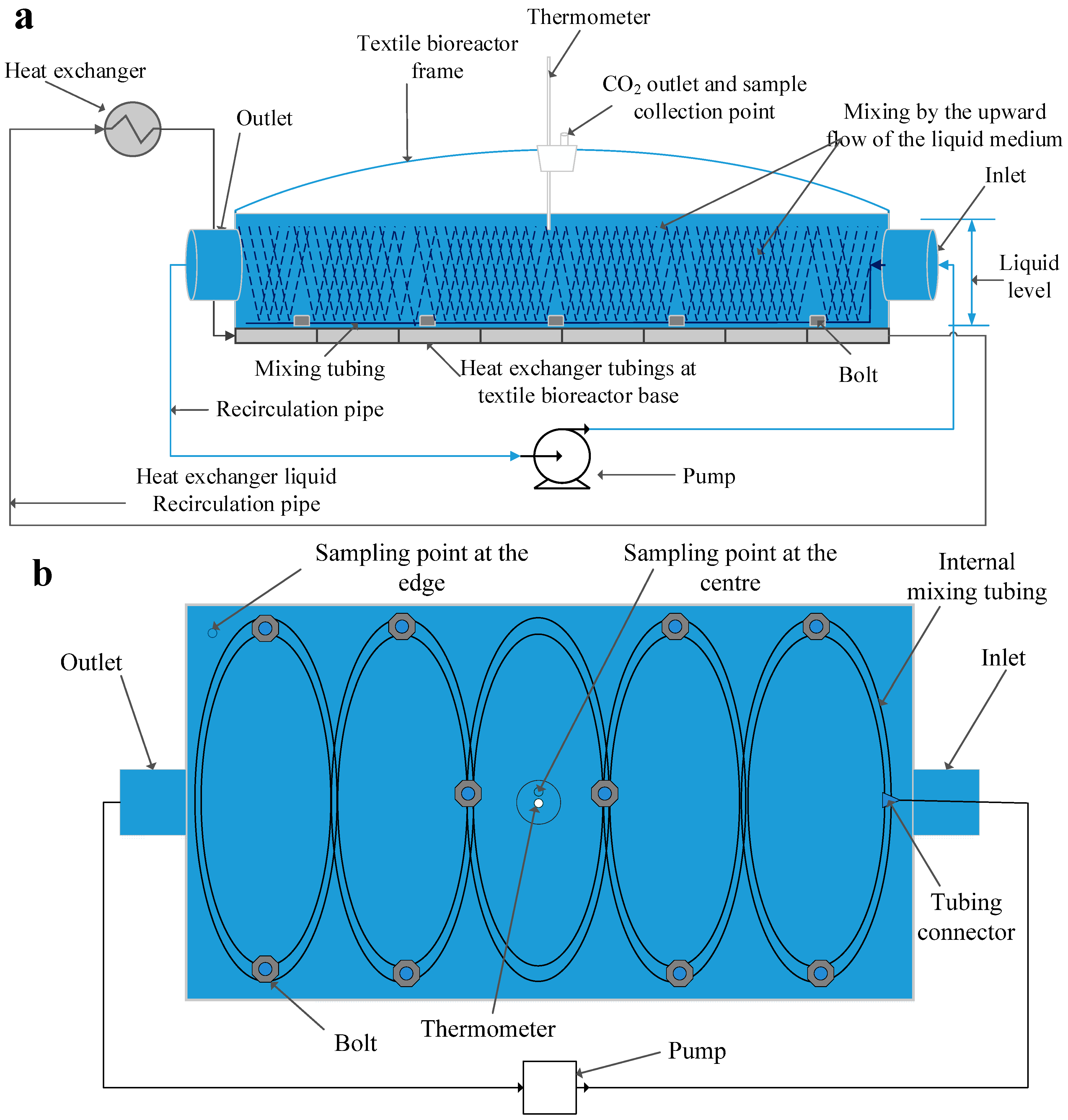
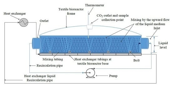
The bioreactor used for this work (Ethanolic textile lab reactor ETLRII, FOV Fabrics AB, Borås, Sweden), was a 30 L laboratory scale reactor with a working volume of 25 L. Its dimensions were 110 cm length, 8 cm depth, and 34 cm width (Figure 1a). The inlet and outlet diameter were 5 cm. It had a 4 cm opening at the middle that served as a sample collection point, a gas outlet, and a thermometer stand. Tubing was connected to the inlet and outlet of the bioreactor for recirculation.
A 12 m silicone peroxide tubing with 5 mm internal diameter and 8 mm external diameter (VWR International, Leuven, Belgium) was used as the internal mixing tubing in the bioreactor. Holes of 0.42 mm at 1 cm intervals were made in the tubing. The tubing was wound around the perimeter of the bioreactor twice and then joined into five elliptical ribbons by plastic fasteners (Figure 1b). The tubing was kept in the liquid phase by means of ten stainless steel bolts, each having internal and external diameters of 2.4 and 3.5 cm respectively, and weighing 94.6 g. The two ends of the tubing used for mixing were connected to the inlet tubing from the pump. A peristaltic pump (405U/L2 Watson-Marlow, Stockholm, Sweden) was used for recirculation, feeding, and discharging the content of the bioreactor.
Figure 1. Developed textile bioreactor showing internal mixing inside the bioreactor from (a) a side view, and (b) a top view of the internal mixing system inside the bioreactor.
Fermentation 01 00098 g001

2.3. Mixing in the Bioreactor

First 20 L distilled water was fed to the bioreactor. Then, 90 ± 5 mL of 100 ppm bromophenol blue solution was added to the bioreactor at one of its ends (hereafter referred to as the injection point). The content of the bioreactor was recirculated through the internal mixing tube at flow rates of 0.002 and 0.015 volume per volume per minute (VVM). Samples were taken from the two opposite rear edges of the bioreactor. The absorbance of the samples was measured by a spectrophotometer (Biochrom Libra S60, Cambridge, UK) at 592 nm [13]. Mixing during fermentation was carried out by recirculation. To determine the effectiveness of mixing in experiments performed with internal mixing tubing, samples were taken from two sampling points, one at the center of the bioreactor and another at its edge. The samples were taken at a depth of 8 cm and from the surface of the liquid medium in the bioreactor.

2.4. Analytical Methods

Biomass was rinsed with distilled water and dried in an oven at 70 °C for 24 h, and its concentration was reported in g/L. Samples from the bioreactor were analyzed using a hydrogen-based ion exchange column (Aminex HPX-87H, Bio-road, Hercules, CA, USA) in a high performance liquid chromatography (HPLC) at 60 °C and 5 mM 0.6 mL/min H2SO4 eluent. A refractive index detector (Waters 2414, Waters Corporation, Milford, MA, USA) was used with the HPLC. Before being used for HPLC analysis, the samples were centrifuged for 5 min at 10,000× g and the liquid portion stored at −20 °C. Concentrations reported for all fermentation experiments were the amount determined by HPLC.
Scanning for the highest peak was used to determine the best wavelength for measuring the absorbance of bromophenol blue samples from the bioreactor. The settling rate of the flocculating yeast used for the experiment was determined using a sedimentation column. Biomass concentration of 2 g/L dry weight was released into a sedimentation column that was filled to 10 cm with the media for fermentation, and the content was mixed. The time taken for the flocs to settle to the base of the column was recorded as the settling time. The distance that the flocs settled from was divided by the settling time to give the settling velocity (Vs).

2.5. Experimental Setup for Fermentation

Fermentation experiments with and without internal mixing tubing and different flow rates (0.0016–0.06 VVM) as process variables were carried out anaerobically in the textile bioreactor. Sucrose (50–55 g/L) was used as the energy and carbon source for the flocculating yeast. It was supplemented with 1.0 g/L yeast extract, 7.5 g/L (NH4)2SO4, 3.5 g/L KH2PO4, and 0.75 g/L MgSO4 7H2O. The liquid volume in the reactor for all experiments was 25 L. Sucrose concentration dropped between 51–45 g/L after the feed to the textile bioreactor was autoclaved. Each experiment was performed in duplicate. The error bars shown on all figures represent standard deviation values generated from the duplicated experiments.

2.6. Fluidization of the Flocs in the Bioreactor

The four forces exerted on a particle during free settling are shown in Equation (1) [14]. On the verge of fluidization, the drag force becomes equal to the pressure force acting on the flocs, and the force due to acceleration becomes zero [14]. The resulting force balance equation is shown in Equation (2). The minimum flow rate to establish this condition occurs when the superficial velocity (V0) is equal to the fluid upwards velocity (Vu). To prevent the flocs from be carried away from the bioreactor, the maximum fluid upwards velocity (Vumax) should be equal to the flocs’ settling velocity (Vs) [15]. For Reynolds numbers less than 10, these velocities can be obtained from Equations (3) and (4) [15]. Where ρp is the density of the particle, ρf is the density of the fluid, g is acceleration due to gravity, Dp is the particle diameter, μ is the viscosity, and ε is the void fraction.
Force due to acceleration = Force due to gravity − Buoyancy force − Drag force
Pressure force (Fp) = Force due to gravity (Fg) − Buoyancy force (FB)
V0 = Vu = (ρp − ρf)gDp2ε3/150 μ (1 − ε)
Vumax = Vs = (ρp − ρf)gDp2/18 μ
For the textile bioreactor prototype used in this work, the superficial velocity is defined in Equation (5), where Q is the liquid flow rate in m3/s and A is the surface area. The velocity of the fluid (Vi) going through the mixing tubing is defined in Equation (6), where Ai is the internal area of the tubing. Using the continuity principle, the velocity at which the fluid leaves the small holes in the tubing is 142 (i.e., 2.52/0.212) times higher than that at which it enters [15]. However, as the tubing is 12 m long and the holes are spaced 1 cm apart, there were 1200 holes. So, the upward velocity (Vh) with which the fluid emerges would split accordingly. This is shown in Equation (7). For fluidization to begin and be sustained in the developed textile bioreactor, Equation (8) shows the governing criteria:
V0 = Q/A = Q/(1.1 × 0.34) = 2.674Q (m/s)
Vi = Q/Ai = Q/(π × ri2) = 5.094 × 10⁴Q (m/s)
Vh = 142 × Vi/1200 = 6.028 × 10³Q (m/s)
V0VhVs

2.7. Statistical Analysis

All statistical analyses were performed with the MINITAB® software package. Results were analyzed with ANOVA (analysis of variance), using general linear model, and factors were considered significant when they had p-value less than 0.05. The analysis was performed on the results obtained from samples measured from the start of the experiment up until the 32nd hour, when stationary phase was reached. Ethanol and sucrose concentrations were used as the response variables, the position from which the sample was taken was used as the main factor, while time and number of runs served as blocking factors.

3. Results and Discussion

Possible ways to reduce the fermentation cost in a bioethanol plant includes process development, utilizing new and cheaper bioreactors, and making the separation process more efficient. This work combines these ideas in developing the textile bioreactor. The newly developed textile bioreactor has the high flexibility, ease of operation and installation, good mechanical strength, high thermal tolerance, low purchase cost, resistance to corrosive fermentation media, and ease of transportation of its previous prototype [11]. It has a new mixing system that eliminates the need for mixing by using either axial flow impellers or aeration spargers. This removes the purchasing and operational cost associated with the maintenance of those devices. A highly flocculating yeast strain with a settling rate of 1 cm/s was used to examine the performance of the developed textile bioreactor for bioethanol production. The efficiency of mixing (a measure of the mass transfer efficiency) in the developed textile bioreactor and the flow rate needed to maintain optimal contact between the flocculating yeast and bioreactor content were investigated in this work.

3.1. Maintaining Optimal Flocs Contact in the Textile Bioreactor

Increasing the surface contact area of enzymes or catalyst in the form of a fluidized bed generally increases the speed at which a chemical reaction takes place [14]. Thus, flocculating yeast retained in a bioreactor in the form of fluidized particles would result in more rapid utilization of the substrate in the bioreactor. Using Equations (5) to (7), different fluid upflow velocities and superficial velocities for different flow rates were generated, and their values are shown in Table 1. As seen in this table, the required velocity needed to begin fluidization is low. This is because the textile bioreactor prototype used for this analysis has a high surface area to volume ratio of 12.5 m2/m3. The superficial velocity reduces with increasing surface area to volume ratio, so the upflow velocity needed on the verge of fluidization would be less for bioreactors having a higher surface area to volume ratio.
Table 1. The fluid upflow velocity generated at different flow rate in the textile bioreactor. VVM: volume per volume per minute; V0: Superficial velocity; Vi: Fluid velocity; Vh: Fluid upflow velocity; Vs: Flocs settling velocity.
Q (VVM)V0 (m/s) × 106Vi (m/s)Vh at Different Hole Spacing (m/s)Vs (m/s)
1 cm Spacing5 mm Spacing2 mm Spacing
0.00161.780.030.0040.0020.0010.01
0.012013.370.250.0300.0150.0060.01
0.016017.830.340.0400.0200.0080.01
0.032035.640.680.0800.0400.0160.01
0.060066.841.270.1510.0750.0300.01
For continuous production of bioethanol using flocculating yeast, it is desirable to carry out the production at a high dilution rate and at the same time prevent washout. From Equation (8), washout could occur when the fluid upflow velocity (Vh) exceeds the flocs settling velocity (Vs). From Table 1, it can be observed that washout would occur in this textile bioreactor prototype if operated on a dilution rate greater than 0.72 h−1 (i.e., Q ≥ 0.012 VVM), as Vh is greater than Vs. One way to increase the dilution rate would be to increase the number of holes by reducing the space between consecutive holes in the mixing tubing. From Table 1, reducing the space between the tubes to 2 mm would allow the bioreactor to be operated at a dilution rate of 1 h−1 with lesser tendency for washout, as Vh equals Vs with this condition. Another possibility of increasing the dilution rate would be to use mixing tubing of a length longer than 12 m. For example, using 18 m long tubing at 2 mm spacing, from equation 7, at Q = 0.02 VVM (dilution rate of 1.2), Vh becomes 0.007 m/s, which is less than the settling velocity of 0.01 m/s. Normally, at a dilution rate greater than the growth rate, washout would occur, but with this type of configuration for the mixing tubing, even with dilution rate higher than growth rate, washout would not occur.

3.2. Mixing as a Means of Reducing Mass Transfer Limitations
Efficient mass transfer is important for optimal performance in any bioreactor, as it helps to facilitate transfer of substrate into and product out of the microorganism, and prevent improper cell growth in the bioreactor [7]. Mass transfer is influenced by two factors: the diffusional flux between the cells and the liquid media, and the bulk flow of the liquid media. The first factor is influenced by the diffusivity of the product or substrate into the liquid media. The second is enhanced by the mixing system in the bioreactor, like agitation, aeration, or the use of stirrers [16]. With the theoretical understanding of how the flow rate can influence good contacting pattern in the previous section, experimental verifying the theoretical concepts are presented in this section.
For bioreactors utilizing flocculating yeast, mass transfer limitations need to be adequately considered. There needs to be a balance between having flocs of large sizes, favorable for the enhancement of cell retention in the bioreactor, and reducing the size of the flocs, which is necessary for the reduction of the mass transfer limitations. Characterizing solute transport into and out of the flocs is challenging because of the fragile nature of the flocs and the difficulty in deciding the geometry the flocs actually have inside the bioreactors [3]. The approach in this article was to relate the mass transfer due to diffusion to the coefficient of diffusivity, and the flow rate of the liquid media being recirculated as a measure of that due to the bulk flow of the liquid [17].
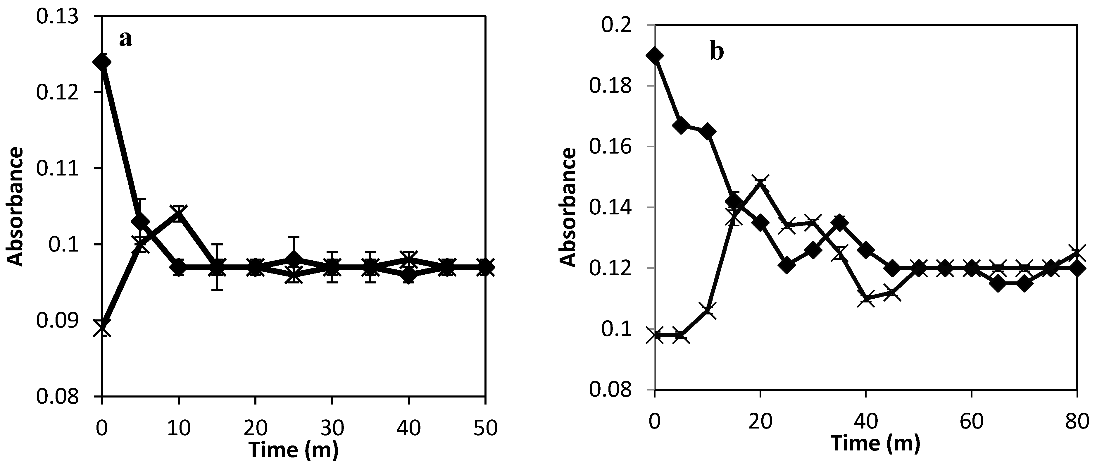
Figure 2 shows the result of the absorbance of bromophenol blue measured across the textile bioreactor at different flow rates. At 0.015 VVM, equilibrium was reached in the textile bioreactor in 15 min. At a flow rate of 0.002 VVM, equilibrium was reached in 50 min. At 25 °C, the diffusion coefficient of bromophenol blue in water is 3 × 10⁻¹⁰ m2/s [18], that of ethanol in water is 1.24 × 10⁻⁹ m2/s, that of sucrose in water is 5.24 × 10⁻¹⁰ m2/s, and that of water in water is 2.45 × 10⁻⁹ m2/s [19]. The lower diffusivity of bromophenol blue than that of the product and substrate serves as a benchmark for understanding the influence of diffusivity on mass transfer under limiting product or substrate conditions [20]. Achieving equilibrium in 50 min at a flow rate of 0.002 VVM is sufficient, as the sampling time for experiments on bioethanol production is usually measured in hours [21].
Figure 2. Bromophenol blue absorbance variation in the textile bioreactor at (a) a flow rate of 0.015 VVM, and (b) at a flow rate of 0.002 VVM at the injection point (♦) and at the opposite end (×).
Fermentation 01 00098 g002

3.2.1. Mass Transfer Enhancement by Internal Mixing Tubing in the Textile Bioreactor

The internal tubing had holes of 0.42 mm diameter which were 1 cm spread apart all through the textile bioreactor. Both ends of the tubing were connected to the input stream from the pump. The size of the holes and the continuous inflow of the liquid medium generate a pressure difference between the input stream and the fluid inside the tubing. A diameter of 0.42 mm was used because using a larger diameter would result in the incoming fluid leaving the tubing only from the entrance, and a smaller size would generate high back pressure on the pump.
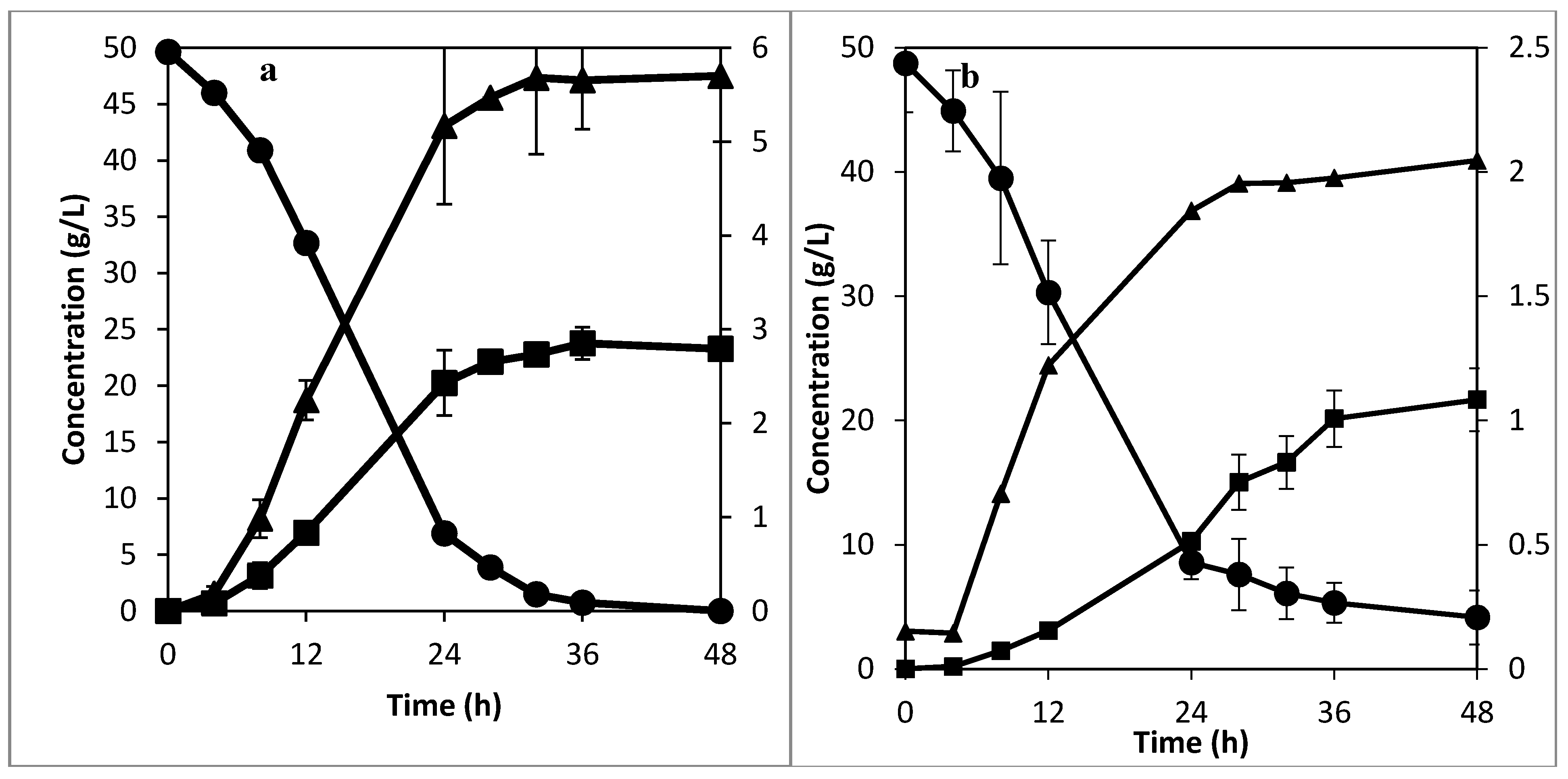
The holes in the internal tubing create upward flow of the liquid stream, which helps in re-suspending the settling flocs, thus improving the mass transfer rate inside the textile bioreactor. To test this idea, fermentation experiments were carried out in the textile bioreactor. Figure 3a shows the result with internal tubing to aid mixing at 0.0016 VVM, while Figure 3b shows the result when mixing is not aided at a flow rate of 0.032 VVM. A lower flow rate was used for the case with aided mixing to show that the result obtained was not due to the flow rate but due to the mixing system itself—as demonstrated in Figure 2a, higher flow rate has been shown previously to improve mass transfer. The same starting concentration of 2 g/L dry weight flocculating yeast was used in both cases. For the aided mixing case (Figure 3a), the fermentation process and sucrose consumption was complete after 36 h, while the unaided mixing experiment (Figure 3b) still had more than 4 g/L of unconsumed sucrose after 48 h. The longer time in Figure 3b is attributable to the settling of the flocs at the bottom of the textile bioreactor, which causes uneven consumption of the substrate in the reactor. The superficial velocity for Figure 3b from Table 1 is 3.6 × 10⁻⁵ m/s, which can be met by the velocity of the CO2 gas bubbles rising from the bottom of the reactor, at the onset of the fermentation experiment. This could explain the higher substrate consumption during the first 28 h of fermentation than in the latter part. However, when the sucrose at the bottom of the reactor is consumed, there will no longer be CO2 bubbles to re-suspend the settled flocs, so the flocs at the bottom of the reactor, because of the mass transfer limitation, would go into the stationary phase faster, resulting in longer fermentation time or incomplete utilization of the substrate. In Figure 3a, the upward flow of the liquid stream helped to keep the flocs uniformly distributed in the textile bioreactor through the duration of the fermentation experiment. This shows that the developed mixing system for the textile bioreactor is effective in preventing ineffective substrate utilization and increasing the fermentation rate. From Figure 3a, the average peak ethanol concentration was 22.13 ± 0.93 g/L. Using the average fermentation time gave the specific ethanol productivity in the developed textile bioreactor with aided mixing at 0.0016 VVM as 0.29 ± 0.01 g-ethanol/g-biomass/h. The best specific productivity from a gas lift reactor with recycle was reported as 0.045 g-ethanol/g-biomass/h with no sugar loss, and 0.43 g-ethanol/g-biomass/h with significant sugar loss [22]. For an airlift reactor, optimum specific productivity of 0.4 g-ethanol/g-biomass/h with significant sugar loss has been reported [23]. Comparing the reported specific productivity of different bioreactors for ethanol production from literature with that of the developed textile bioreactor, it can be seen that for an optimal combination of high specific productivity and complete sugar utilization, the developed textile bioreactor performs better.

3.2.2. Higher Flow Rate with and without Internal Tubing
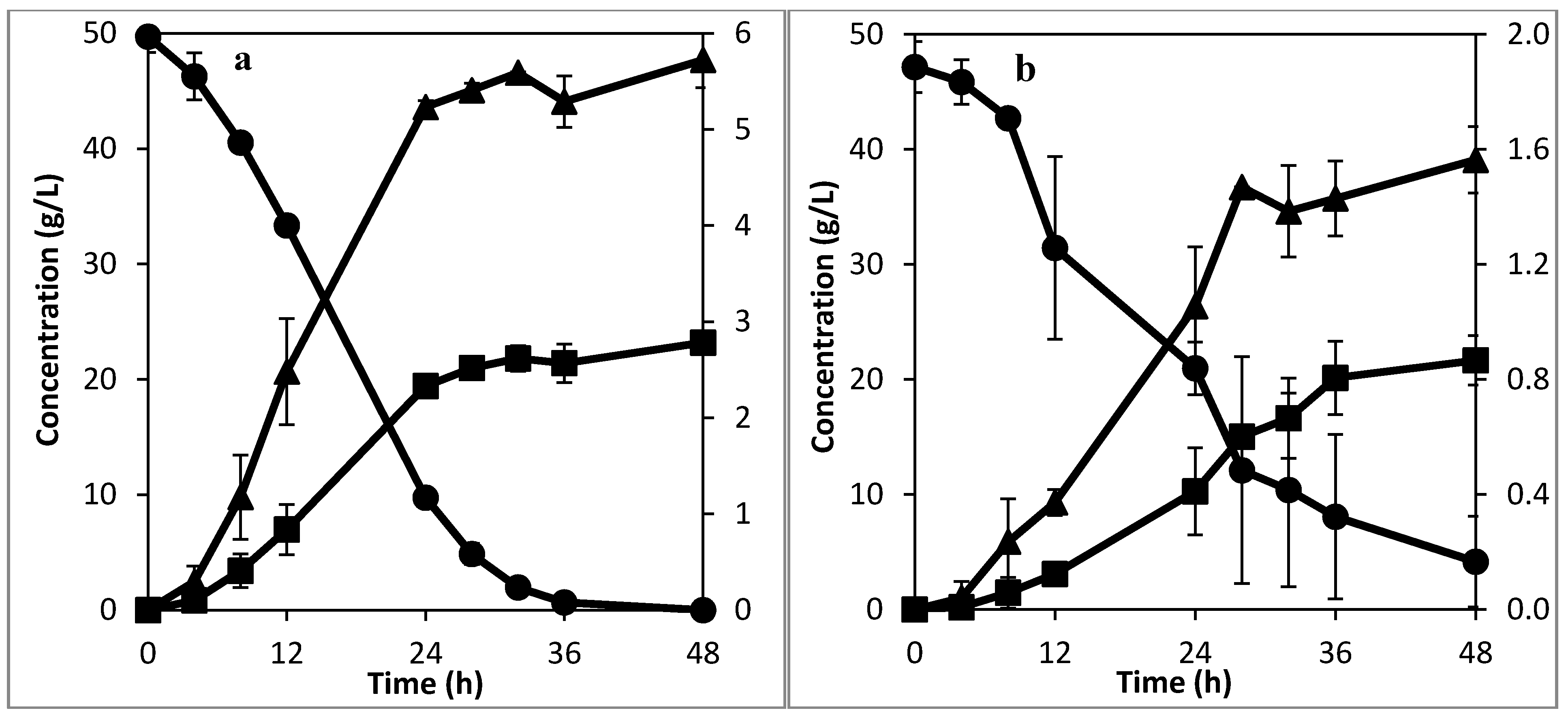
The mass transfer rate can be enhanced to an extent by increasing the bulk flow of the liquid media [16]. The effect of higher flow rate on the fermentation rate was investigated. For the textile bioreactor with internal mixing tubing, a flow rate of 0.012 VVM (7.5 times higher than the previously examined flow rate) was used as the recirculation rate in the textile bioreactor with internal mixing tubing. Figure 4a shows the result of this experiment. From Figure 4a, the fermentation rate was slightly faster in the first 32 h of fermentation in comparison to the experiment with a recirculation rate of 0.0016 VVM. However, the substrate was fully consumed after 36 h in both cases. This shows that mixing is not the rate limiting step in both cases, but rather sucrose hydrolysis and slow fructose utilization [22]. This limitation can be handled in several ways such as operating the reactor in a fed-batch mode [24], or by maintaining a high concentration of flocs in the bioreactor [22]. However, for continuous production, using a flow rate of 0.012 VVM at 1 cm hole spacing would cause washout to occur much faster than that at a flow rate of 0.0016 VVM (Table 1). This did not affect the fermentation rate in the experiment performed at a flow rate of 0.012 VVM because the cells were recycled back into the textile bioreactor.
Figure 3. Experiment with enhanced mixing at (a) a recirculation rate of 0.0016 VVM , and (b) without enhanced mixing at 0.032 VVM, showing ethanol (■) and sucrose (●) concentration in the primary axis (right hand side), and glycerol concentration (▲) in the secondary axis.
Fermentation 01 00098 g003
For the case without the mixing tubing, a flow rate of 0.06 VVM (1.9 times higher than the previously examined flow rate) was used as the recirculation rate. The result of this experiment is shown in Figure 4b. Comparing the experiment performed at 0.06 VVM with that at 0.032 VVM shows that the higher recirculation flow rate increased the fermentation rate. However, the higher flow rate was not sufficient to cause complete utilization of the sucrose within 48 h because the settling rate of the flocs is higher than the turbulence created by the high flow rate. Comparing the experiment performed at 0.0016 VVM with that performed at 0.06 VVM shows that the developed mixing system is much more effective in overcoming mass transfer limitations associated with mixing, even with 30 times slower flow rate.
Figure 4. Experiments with (a) enhanced mixing at 0.012 VVM, and (b) without enhanced mixing at a recirculation rate of 0.06 VVM , showing ethanol (■) and sucrose (●) concentration in the primary axis (right hand side), and glycerol concentration (▲) in the secondary axis (left hand side).
Fermentation 01 00098 g004

3.3. Mixing along the Edges of the Textile Bioreactor

One of the limitations of a rectangular reactor is the possibility of it having poor mixing, especially at the edges [25]. Ethanol and sucrose concentrations across different sampling positions in the developed textile bioreactor at a recirculation rate of 0.0016 VVM are shown in Table 2. From Table 2 it can be seen that the concentrations of ethanol and sucrose from different sampling points and depths are similar. ANOVA using a general linear model of ethanol and sucrose concentration as responses and sampling position as factor gave p-values of 0.861 for ethanol and 0.733 for sucrose, so the position from which the sample is drawn is not statistically significant, meaning that the mixing is uniform at all points in the textile bioreactor. This uniformity in the textile bioreactor implies that the flocs responsible for the conversion of substrate to product is uniformly distributed across the developed textile bioreactor. From this it can be seen that the developed textile bioreactor does not have regions with significant ethanol or sucrose concentration variation, so there will be efficient and fast utilization of the substrate across it.
Table 2. Ethanol and sucrose concentrations from different sampling point in the textile bioreactor.
Time (h)RunEthanol Concentration (g/L)Sucrose Concentration (g/L)
Edge 8 cm DeepEdge SurfaceCentre 8 cm DeepCentre SurfaceEdge 8 cm DeepEdge SurfaceCentre 8 cm DeepCentre Surface
010.000.000.000.0048.9648.4648.7548.75
410.860.450.510.4746.2244.9744.8444.84
812.392.302.152.3843.6141.9140.9740.97
1215.145.415.235.4436.1638.0436.0133.70
24117.9118.2418.8718.8511.615.5212.119.34
28120.4619.9520.6020.443.212.133.145.50
32121.2021.2521.6821.041.351.351.381.39
020.000.000.000.0048.1950.4050.6850.68
421.181.181.271.2146.8646.8647.7247.72
824.564.414.414.4440.8739.9440.1040.10
1228.608.278.238.5332.4130.7731.8432.98
24220.0319.9420.0119.9810.0010.1410.0310.16
28221.9321.6521.8821.524.344.164.314.22
32222.6022.0522.6522.592.302.822.872.55

3.4. Ethanol Production Process Development and Cost Reduction

Ethanol could be produced by batch, fed-batch, or continuous modes of production. Conventionally, ethanol is produced anaerobically, and the yeast cells are centrifuged and either recycled or channeled somewhere else [26]. However, for a 100,000 m3/year ethanol production facility, the centrifuge accounts for 18% of the fermentation investment cost [9], excluding the energy cost. This can be eliminated by using flocculating yeast. Mixing in bioreactors using flocculating yeast is carried out using aeration (so the bioreactor is operated as a bubble column or an airlift reactor) as stirrers breaks the flocs [3]. Despite the Crabtree effect that favors ethanol production by S. cerevisiae under aerobic conditions [27], aerobic conditions cause more biomass production, which reduces the amount of ethanol that can be produced [28]. The developed textile bioreactor has been shown to both anaerobically use flocculating yeast for ethanol production and maintain good mixing, thus it can combine the benefits of optimal ethanol production and elimination of centrifugation cost.
Using the same volume of textile bioreactor in place of a stainless steel reactor has been previously shown to reduce the fermentation investment cost by 19% [11]. Combining this with the savings obtained by not using a centrifuge would result in 37% reduction in the investment cost of a 100,000 m3/year ethanol production facility [9].

4. Conclusions

The developed textile bioreactor showed a better combination of specific ethanol productivity and complete sugar utilization than both gas lift bioreactors with recycle and airlift bioreactors when using flocculating yeast for ethanol production. The results of the anaerobic mixing efficiency with high settling flocculating yeast showed excellent mixing in comparison with the previous prototype. This makes it possible to combine optimal anaerobic ethanol production rates and the process benefits of using flocculating yeast for ethanol production. Additionally, for yeast flocs having average particle diameter between 190 to 320 µm, there is the possibility of operating the bioreactor at a dilution rate of more than 1 h−1 with less chances of washout by using mixing tubing configurations that makes the fluid upflow velocity less than the flocs settling velocity. Using flocculating yeast as the fermenter in the same volume of the developed textile bioreactor as the conventionally used bioreactor in a 100,000 m3/year ethanol production facility can give a 37% reduction in fermentation investment cost.

Acknowledgments

The authors would like to appreciate Magnus Lundin, Peter Therning, and Regina Patinvoh for their technical assistance and valuable discussions. The textile bioreactor used for this article was kindly provided by FOV Fabrics AB (Borås, Sweden).

Author Contributions

Osagie A. Osadolor did the experiment design, performed all the experiment, wrote most of the manuscript and had the idea. Patrik R. Lennartsson was responsible for part of the manuscript. Mohammad J. Taherzadeh was responsible for part of the manuscript. All authors have given their approval for this final version of the manuscript.

Conflicts of Interest

The authors declare no conflict of interest.

References

  1. Balat, M.; Balat, H. Recent trends in global production and utilization of bio-ethanol fuel. Appl. Energ. 2009, 86, 2273–2282. [Google Scholar] [CrossRef]
  2. Mussatto, S.I.; Dragone, G.; Guimarães, P.M.R.; Silva, J.P.A.; Carneiro, L.M.; Roberto, I.C.; Vicente, A.; Domingues, L.; Teixeira, J.A. Technological trends, global market, and challenges of bio-ethanol production. Biotechnol. Adv. 2010, 28, 817–830. [Google Scholar] [CrossRef] [PubMed] [Green Version]
  3. Domingues, L.; Vicente, A.A.; Lima, N.; Teixeira, J.A. Applications of yeast flocculation in biotechnological processes. Biotechnol. Bioprocess. Eng. 2000, 5, 288–305. [Google Scholar] [CrossRef] [Green Version]
  4. Verstrepen, K.J.; Klis, F.M. Flocculation, adhesion and biofilm formation in yeasts. Mol. Microbiol. 2006, 60, 5–15. [Google Scholar] [CrossRef] [PubMed]
  5. Ergun, S.; Orning, A.A. Fluid flow through randomly packed columns and fluidized beds. J. Ind. Eng. Chem. 1949, 41, 1179–1184. [Google Scholar] [CrossRef]
  6. Muroyama, K.; Fan, L.S. Fundamentals of gas-liquid-solid fluidization. AIChE. J. 1985, 31, 1–34. [Google Scholar] [CrossRef]
  7. Blakebrough, N. Fundamentals of fermenter design. Pure Appl. Chem. 1973, 36, 305–316. [Google Scholar] [CrossRef]
  8. Mark, R.; Wilkins, A.H.A. Fermentation. In Food and Industrial Bioproducts and Bioprocessing; John Wiley & Sons: Hoboken, NJ, USA, 2012. [Google Scholar]
  9. Maiorella, B.L.; Blanch, H.W.; Wilke, C.R.; Wyman, C.E. Economic evaluation of alternative ethanol fermentation processes. Biotechnol. Bioeng. 2009, 104, 419–443. [Google Scholar] [CrossRef] [PubMed]
  10. Wei, Y.; Wang, J.; Jia, X.; Yeh, J.-M.; Spellane, P. Polyaniline as corrosion protection coatings on cold rolled steel. Polymer 1995, 36, 4535–4537. [Google Scholar] [CrossRef]
  11. Osadolor, O.A.; Lennartsson, P.R.; Taherzadeh, M.J. Introducing textiles as material of construction of ethanol bioreactors. Energies 2014, 7, 7555–7567. [Google Scholar] [CrossRef]
  12. Van Hamersveld, E.H.; van der Lans, R.; Luyben, K. Quantification of brewers’ yeast flocculation in a stirred tank: Effect of physical parameters on flocculation. Biotechnol. Bioeng. 1997, 56, 190–200. [Google Scholar] [CrossRef]
  13. Nagai, Y.; Unsworth, L.D.; Koutsopoulos, S.; Zhang, S. Slow release of molecules in self-assembling peptide nanofiber scaffold. J. Control. Release 2006, 115, 18–25. [Google Scholar] [CrossRef] [PubMed]
  14. Kunii, D.; Levenspiel, O. Fluidization Engineering; Elsevier: Amsterdam, The Netherlands, 2013. [Google Scholar]
  15. McCabe, W.L.; Smith, J.C.; Harriott, P. Unit Operations of Chemical Engineering; McGraw-Hill: New York, NY, USA, 1993; Volume 5. [Google Scholar]
  16. Benitez, J. Principles and Modern Applications of Mass Transfer Operations; John Wiley & Sons: Hoboken, NJ, USA, 2011. [Google Scholar]
  17. Bergman, T.L.; Incropera, F.P.; Lavine, A.S. Fundamentals of Heat and Mass Transfer; John Wiley & Sons: Hoboken, NJ, USA, 2011. [Google Scholar]
  18. West, J.; Gleeson, J.P.; Alderman, J.; Collins, J.K.; Berney, H. Structuring laminar flows using annular magnetohydrodynamic actuation. Sensor Actuator B 2003, 96, 190–199. [Google Scholar] [CrossRef]
  19. Hayduk, W.; Laudie, H. Prediction of diffusion coefficients for nonelectrolytes in dilute aqueous solutions. AIChE. J. 1974, 20, 611–615. [Google Scholar] [CrossRef]
  20. Bosma, T.N.P.; Middeldorp, P.J.M.; Schraa, G.; Zehnder, A.J.B. Mass transfer limitation of biotransformation: Quantifying bioavailability. Environ. Sci. Technol. 1996, 31, 248–252. [Google Scholar] [CrossRef]
  21. Elander, R.T.; Putsche, V.L. Ethanol from Corn: Technology and Economics; Taylor and Francis: Washington, DC, USA, 1996; pp. 329–349. [Google Scholar]
  22. Fontana, A.; Ghommidh, C.; Guiraud, J.P.; Navarro, J.M. Continuous alcoholic fermentation of sucrose using flocculating yeast. The limits of invertase activity. Biotechnol. Lett. 1992, 14, 505–510. [Google Scholar] [CrossRef]
  23. Sousa, M.L.; Teixeira, J.A.; Mota, M. Comparative analysis of ethanolic fermentation in two continuous flocculation bioreactors and effect of flocculation additive. Bioprocess. Eng. 1994, 11, 83–90. [Google Scholar] [CrossRef]
  24. Echegaray, O.F.; Carvalho, J.C.M.; Fernandes, A.N.R.; Sato, S.; Aquarone, E.; Vitolo, M. Fed-batch culture of sacchoromyces cerevisiae in sugar-cane blackstrap molasses: Invertase activity of intact cells in ethanol fermentation. Biomass Bioenergy 2000, 19, 39–50. [Google Scholar] [CrossRef]
  25. Oca, J.; Masaló, I. Design criteria for rotating flow cells in rectangular aquaculture tanks. Aquacult. Eng. 2007, 36, 36–44. [Google Scholar] [CrossRef]
  26. Basso, L.C.; Rocha, S.N.; Basso, T.O. Ethanol Production in Brazil: The Industrial Process and its Impact on Yeast Fermentation; Intech: Rijeka, Croatia, 2011. [Google Scholar]
  27. Verduyn, C.; Zomerdijk, T.P.L.; van Dijken, J.P.; Scheffers, W.A. Continuous measurement of ethanol production by aerobic yeast suspensions with an enzyme electrode. Appl. Microbiol. Biotechnol. 1984, 19, 181–185. [Google Scholar] [CrossRef]
  28. Taherzadeh, M.J.; Lennartsson, P.R.; Teichert, O.; Nordholm, H. Bioethanol production processes. Biofuels Prod. 2013, 211–253. [Google Scholar] [CrossRef]