Article

Bottom-Up Synthesis Strategies Enabling the Investigation of Metal Catalyst-Carbon Support Interactions

by
Hamed Bateni
1,2,*,
Prathamesh T. Prabhu
1,2,
Hannah E. Gebur
1,2 and
Jean-Philippe Tessonnier
1,2,*
1
Department of Chemical and Biological Engineering, Iowa State University, Ames, IA 50011, USA
2
Center for Biorenewable Chemicals (CBiRC), Ames, IA 50011, USA
*
Authors to whom correspondence should be addressed.
Submission received: 11 May 2022 / Revised: 9 June 2022 / Accepted: 15 June 2022 / Published: 28 June 2022
(This article belongs to the Collection Young Carbon Scientists)

Abstract

:
The structural versatility and vibrant surface chemistry of carbon materials offer tremendous opportunities for tailoring the catalytic performance of supported metal nanoparticles through the modulation of interfacial metal-support interactions (MSI). MSI’s geometric and structural effects are well documented for these materials. However, other potential support effects such as electronic metal-carbon interactions remain poorly understood. Such limitations are tied to constraints intrinsic to commonly available carbon materials such as activated carbon (e.g., microporosity) and the top-down approach that is often used for their synthesis. Nonetheless, it is crucial to understand the interplay between the structure, properties, and performance of carbon-supported metal catalysts to take steps toward rationalizing their design. The present study investigates promising and scalable bottom-up synthesis approaches, namely hydrothermal carbonization (HTC) and evaporation-induced self-assembly (EISA), that offer great flexibility for controlling the carbon structure. The opportunities and limitations of the methods are discussed with a particular focus on harnessing the power of oxygen functionalities. A remarkable production yield of 32.8% was achieved for mesoporous carbons synthesized via EISA. Moreover, these carbon materials present similar external surface areas of 316 ± 19 m2/g and average pore sizes of 10.0 ± 0.1 nm while offering flexibility to control the oxygen concentration in the range of 5–26 wt%. This study provides the cornerstone for future investigations of metal-carbon support interactions and the rational design of these catalysts.

1. Introduction

Carbon materials have a long-standing history in the catalysis industry [1]. They particularly hold promising potential for substituting oxide supports for liquid-phase reactions in aqueous media due to their excellent hydrothermal stability (even under acidic and basic conditions), tunable structure and surface chemistry, shaping flexibility, ease of active phase recovery, and low manufacturing cost in the case of conventional supports [2,3,4,5]. These properties are especially desired in modern catalysis research, namely for the thermocatalytic upgrading of lignocellulosic biomass and for electrocatalytic applications in energy conversion, chemical manufacturing, and environmental remediation.
The primary role of support materials in (electro)catalysis is to serve as a scaffold for the dispersion of metal nanoparticles (i.e., active sites) and ensure the optimal utilization of the metal active phase [2,6]. Additionally, it is known that the support can affect the catalytic performance of nanoparticles through metal–support interactions (MSI) [2,6,7]. The impact of the carbon scaffold on the nanoparticles is tied to its physicochemical and electronic properties. Specifically, the carbon’s structure and surface chemistry strongly influence its proton-, electron-, and oxygen-transfer characteristics [1,2]. Oxygen-containing groups play a substantial role as they are ubiquitous on carbon surfaces [1,8] and control the hydrophilic-hydrophobic, acid-base, and local electronic structure of the surface through distortion of carbon’s sp2 network [9]. Hence, they may influence the adsorption and chemical events involved in the catalytic transformations, for example, through proton shuttling, as well as the electronic structure of the metal active phase itself. In fact, they serve as linkers to covalently bond metal atoms to the carbon support and transfer charge between them [6]. A recent study disclosed an interfacial charge transfer for Pd/C that scaled with the amount of surface oxygen moieties and that altered the selectivity of the Pd/C catalyst for the liquid-phase hydrogenation of cinnamaldehyde [10]. Nevertheless, the exact role of oxygen-containing groups on the properties of the carbon support and the decorating metal nanoparticles remains poorly understood [9]. The intertwined confinement, chemical, and electronic effects were proven to be difficult to decouple in many previous studies causing ambiguity in the literature and hampering the rational design of these catalysts [2].
Generally, both top-down and bottom-up approaches are used to produce carbon supports [11]. However, the top-down approach is often limited to commercial carbon products (i.e., activated carbon and carbon black) with limited opportunity for precise control over the physicochemical properties of these materials. In contrast, the bottom-up approach offers flexibility in engineering the microstructure and chemistry of carbon materials at the nanoscale, enabling a rigorous investigation of carbon support’s effect on metal nanoparticles. Some of the common bottom-up carbon synthesis approaches include chemical vapor deposition (CVD), carbonization (i.e., carbonization of non-, soft-, and hard-templated precursors), and hydrothermal carbonization (HTC) [12,13,14,15,16]. CVD is often employed in synthesizing specialty carbon materials such as graphene and carbon nanotubes [13]. However, the use of these supports is limited due to several development challenges discussed in great details elsewhere [17]. The hard-templating technique offers promising potential in controlling the porous structure of carbon materials [18]. In this method, the precursor is carbonized on a metal or inorganic scaffold (template), which ‘molds’ the carbon layers [16]. However, the hard-templating method suffers from scalability limitations due to a low production yield. Another caveat is the subsequent template removal, where concentrated HF, HCl, HNO3, or NaOH is typically employed [18]. An imperfect template removal or an inadvertent insertion of heteroatoms from the leaching agent can drastically affect the carbon support’s chemical and electronic properties and its effect on the metal active phase. The role of heteroatoms has been an area of increasing attention in the doped-carbon literature.
Here, we study the scalable synthesis of carbon supports with tailored properties with a particular focus on surface oxygen functionalities using HTC and soft-templated evaporation-induced self-assembly (EISA). We demonstrate that these techniques mitigate the concerns over an unintentional insertion of foreign elements and deliver carbon supports for a wide range of research studies where the confinement effect can be decoupled from other support effects.

2. Materials and Methods

2.1. Materials

D-glucose (anhydrous), hydrochloric acid (37% in water), citric acid monohydrate (≥99.5%), nitric acid (67–70%), acetic acid (99.7%), and formaldehyde solution (37% in water) were purchased from Fisher Chemicals (Fair Lawn, NJ, USA). Formic acid (≥95%), resorcinol (≥99.0%), and Pluronic® F-127 were purchased from Sigma-Aldrich (St Louis, MO, USA).

2.2. Carbon Synthesis Using Hydrothermal Carbonization (HTC)

Hydrothermal carbonization (HTC) of glucose (1.2 M) was performed at 180 °C using 0.2 M hydrochloric acid, 0.2 M formic acid, 0.07 M citric acid, or water. After synthesis, the solid product was separated from the aqueous solution, washed, and dried in an oven at 110 °C overnight. In the case of HCl-catalyzed HTC, the product was subjected to a three-step purification using ethanol, acetone, and water to maximize chlorine removal prior to the drying step. The HTC carbon production yield was calculated by dividing the dry weight of the final product by the initial amount of glucose used in the process. As-synthesized HTC samples were then annealed at different temperatures (200–800 °C) under 200 mL/min of nitrogen.

2.3. Carbon Synthesis Using Evaporation-Induced Self-Assembly (EISA)

An amount of 2.2 g of resorcinol was added to 18 mL of a 1:1 v/v mixture of ethanol and a 3 M aqueous solution of the desired acid, then mixed until fully dissolved. Various acids were tested, namely formic acid, citric acid, acetic acid, nitric acid, and hydrochloric acid. Then, 4.4 g Pluronic F-127 (soft template) was added and stirred for 15 min at room temperature in a closed vessel. Following this, 2.6 g of formaldehyde (37% in water) was slowly added and the mixture was stirred for another 15 min in a closed vessel. The solution was then poured into a Petri dish and dried in the air overnight. The solidified gel was cured at 80 °C and then 120 °C for 24 h per step. The resin film was then removed from the dish and carbonized in a tube furnace under nitrogen flow. The sample was first heated to 350 °C at 1 °C/min, held for 2 h, then heated to the desired temperature at 2 °C/min ramp, and held for 3 h. The highly annealed sample (MC-1000) was subjected to oxidation using concentrated nitric acid (67–70%) at 80 °C for 24 h to reintroduce surface oxygen functionalities.

2.4. Catalyst Synthesis

Incipient wetness impregnation was used to deposit Pd nanoparticles on selected supports. Typically, 300 μL of tetraamminepalladium (II) nitrate solution (10 wt% in water) was mixed with 200 μL of DI water, added dropwise to 200 mg of the carbon support, then sonicated for 5 min. The catalysts were then dried at 80 °C overnight and reduced at 200 °C for 1 h under 100 mL/min of hydrogen flow.

2.5. Characterizations

Elemental analysis was completed using a PE 2100 Series II combustion analyzer (Perkin Elmer Inc, Waltham, MA, USA) with an expected accuracy of ±0.3%. Nitrogen physisorption was performed using a Micromeretics ASAP 2020 instrument at −196 °C after the sample was dried and degassed at 300 °C for 1 h. Scanning electron microscopy (SEM) was conducted using an FEI Quanta 250 microscope equipped with a field emission gun. A Micromeretics ASAP 2920 analyzer coupled with a mass spectrometer (MS) was employed for temperature-programmed desorption (TPD-MS) studies. X-ray photoelectron spectroscopy (XPS) was conducted using a Kratos Amicus ESCA 3400 instrument equipped with an Mg anode source. Carbon samples were pressed onto a sputter-cleaned copper foil that also served as an internal calibration reference and the analysis was performed using a pass energy of 150 eV. Inductively coupled plasma optical emission spectrometry (ICP-EOS) was used to determine the amount of palladium loaded on various carbon supports. Transmission electron microscopy (TEM) was performed using a JEOL JSM 2100 scanning and transmission electron microscope to evaluate the size and distribution of Pd nanoparticles in the carbon-supported metal catalysts.

3. Results and Discussion

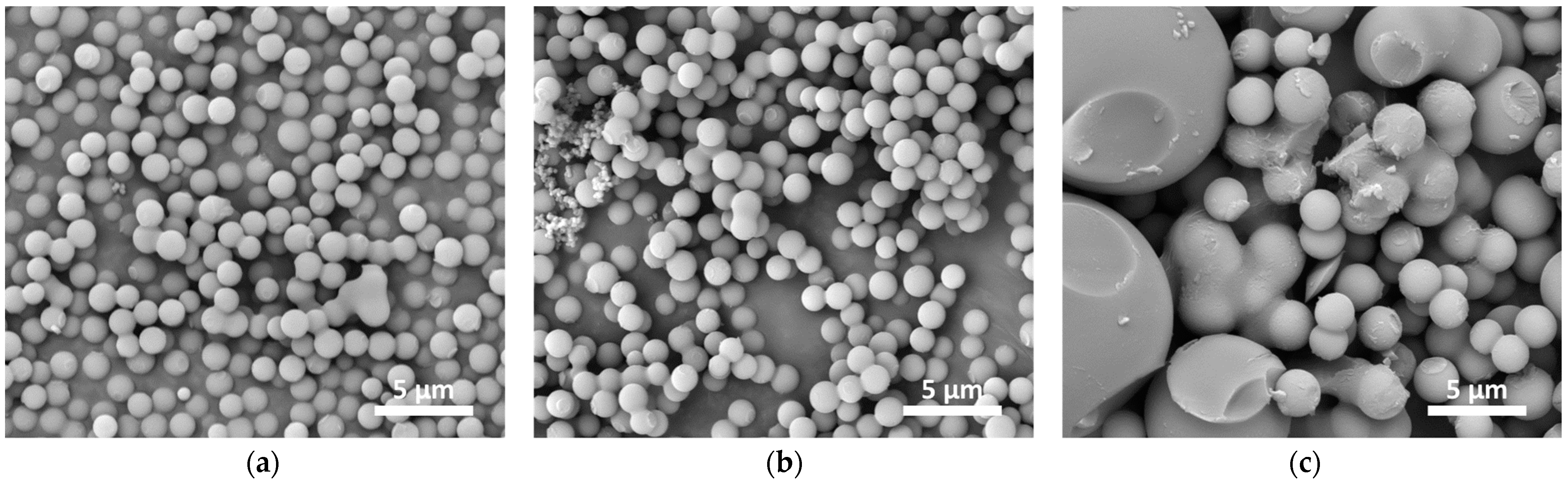
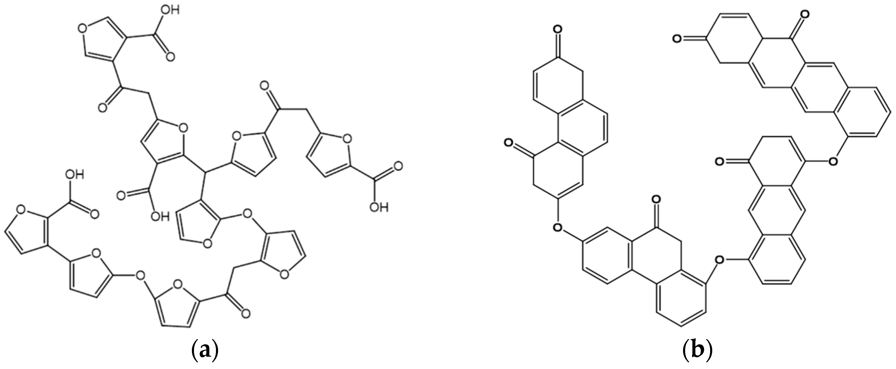
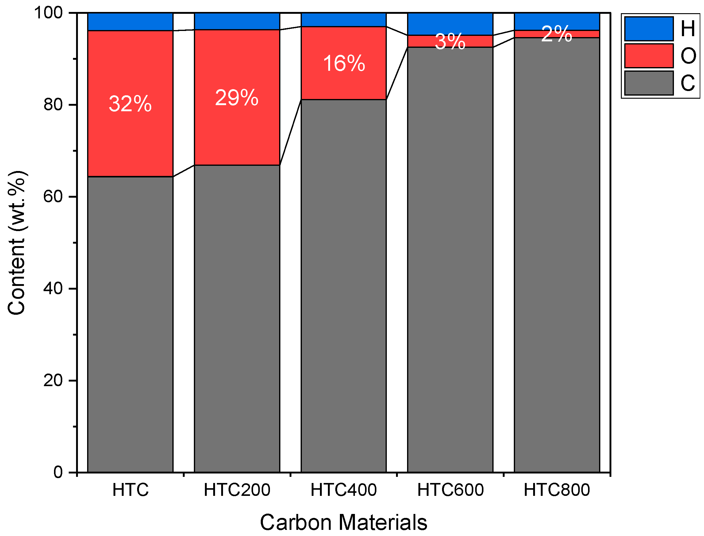
3.1. Hydrothermal Carbonization (HTC)

Hydrothermal carbonization (HTC) is a versatile approach for synthesizing solid carbon materials using an aqueous solution of an organic precursor at relatively moderate temperatures [19,20]. Various organic substances such as sugars (e.g., glucose, fructose) can be used as precursors in HTC. While the reaction can progress in the absence of a catalyst, the presence of a proper acid can significantly accelerate the process. In fact, an extended reaction time of 24 h was required to achieve a 21.8% yield in the absence of a catalyst. The presence of an acid catalyst accelerated the reaction and the rate increased as the pKa of the acid catalyst decreased. Yields of 2.6%, 18.1%, and 21.0% were obtained in only 3 h using formic acid, citric acid, and hydrochloric acid, respectively.
The SEM analysis suggested that the acid catalyst also affects the morphology of the carbon products (Figure 1). HTC in the presence of HCl and formic acid resulted in carbon spheres with a diameter within 1.0–1.5 μm; however, the citric acid resulted in a bi-modal distribution of ~2 μm spheres and large aggregates of 12–15 μm. Previous studies suggested that carbon spheres’ (CSs’) morphology is a function of both starting materials and operating conditions, including the acid strength of the catalysts [19,21]. Nonetheless, similar particle sizes were obtained using both HCl- and HCOOH-catalyzed reactions (Figure 1a,b), suggesting that the reaction mechanism and the formation of the oligomeric intermediates (triggering variations in pH and repulsive/attractive forces in the media) may be vital contributing factors influencing the particle growth and size, which to date has not been fully understood [19].
While previous studies discarded the contribution of the conjugate base (anionic part of the acid) to the size of CSs [22], the potential incorporation of citric acid into the carbon backbone of the CS cannot be overlooked. Zhao et al. [22] suggested that a dispersant (e.g., polyacrylic acid, PAA) is required to obtain monodisperse CSs by HCl-catalyzed HTC. Here, in contrast, we observed an adverse effect on the monodispersity of the CS when PAA was added (12 mg PAA for 5 g glucose), probably due to irregular particle aggregations (Supplementary Materials, Figure S1). Such a phenomenon may be attributed to the low solubility of PAA in acidic media, influencing the homogeneity of the CS precursor solution. More importantly, the ambiguous reaction mechanism creates a substantial challenge for decoupling various factors influencing the morphology of the CSs [19].
It was proposed that under HTC conditions, glucose is first converted to furanic intermediates (primarily 5-HMF) [23], which then undergo intermolecular dehydration and aldol condensation to polymerize and form carbon particles [24]. These particles consist of a hydrophobic core (regions of higher aromatization) and a hydrophilic shell (with a lower aromatization level) [24]. Further NMR investigations of the structure of hydrothermal carbons resulted in the model proposed in Figure 2a [25]. This model explains that the highly oxygenated structure of HTC materials is rich in furanic building blocks where the rings are linked by short aliphatic chains [25].
The as-synthesized carbon spheres showed a low surface area (<5 m2/g) and a nonporous structure with a high oxygen content of 32 wt% (Figure 3). Thus, the surface area and porosity of the sample can be increased via a thermal treatment, as can be seen in Table 1. Annealing CSs at 200 °C did not significantly change the textural properties (Table 1). However, defunctionalization at higher temperatures increased the surface area via the decomposition of oxygen functionalities and the formation of micropores. Table S1 in Supplementary Materials lists the textural properties of HTC materials synthesized under different conditions. The HCl-catalyzed HTC showed larger pores than the formic acid-catalyzed sample after annealing under the same conditions (Entries 3 and 6). Varying the annealing conditions did not result in any notable change in the textural properties of the final carbon supports (Entries 6 and 7). Previous reports suggested that oxidation with hydrogen peroxide followed by heat treatment can introduce mesopores in carbon materials [22]. However, no meaningful increase in the average pore size of the materials was identified using this approach (Entries 8–11). The average pore size was limited to ~4 nm even in the presence of a swelling agent (Entry 13).
The soft-templated HTC using Pluronic F127 in the presence of mesitylene as a swelling agent was used to increase the pore size of the sample carbonized at 800 °C (t-HTC800), leading to an average pore size of 8.0 nm. While such an average pore size is one of the largest reported to date for HTC materials, it should be noted that most of the surface area still comes from micropores, thus challenging the use of these structures as carbon supports for heterogeneous catalysis. Such a limited improvement in the presence of a surfactant (Pluronic F127) may be attributed to the instability of the micelles at elevated temperatures under hydrothermal carbonization conditions. Previous studies suggested the presence of hot spots on some of the polymeric nuclei formed during HTC, along with the formation of CO, CO2, and H2 gases at a high autogenic pressure [19,27], which may create a harsh environment for the micelles to remain intact.
It should be noted that while a high surface area is favorable for catalysis application, diffusion limitations are of primary concern for microporous structures. It is, in fact, the most critical limiting factor for the use of HTC for catalysis applications. However, it should be noted that the flexibility in fine-tuning the textural properties and surface chemistry of these materials provides a great opportunity when confinement effects are desired. The TPD-MS analysis of various functionalized HTC materials highlighted the versatility of these substrates (Supplementary Materials, Figure S2).

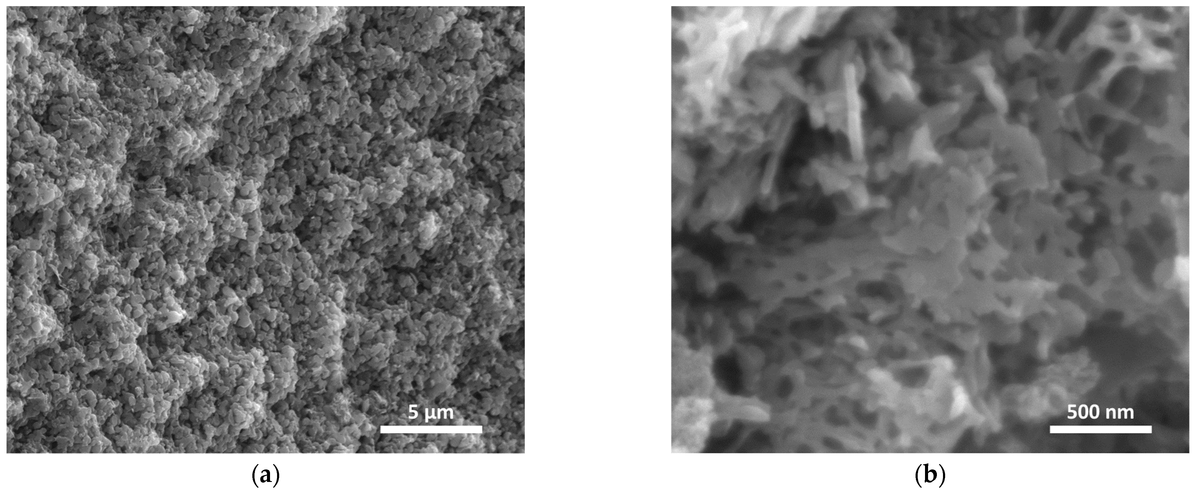
3.2. Evaporation-Induced Self-Assembly (EISA)

Mesoporous carbons are highly desired support materials due to their advantages in mitigating internal mass transfer limitations. The soft templated organic-organic self-assembly method is a promising approach for the production of mesoporous carbon with tailored properties. In the present work, resorcinol and formaldehyde were polymerized around the Pluronic F127 micelles in the presence of an acid catalyst. The resulting resorcinol-formaldehyde (RF) resin was subjected to a carbonization step to decompose the surfactant (i.e., Pluronic F127) and stabilize the carbon framework [28,29]. SEM images (Figure 4) revealed that a mesoporous structure was obtained at the cost of a disturbed and highly inhomogeneous macroscopic morphology. Nevertheless, the ordered microstructure of the composite was confirmed in previous studies, which is beneficial for applications in heterogeneous catalysis [29,30].
Table 2 summarizes the textural properties of the MCs obtained using different acid catalysts. The adsorption isotherms and pore size distributions are also provided in Supplementary Materials, Figure S3. It can be seen that the nature of the acid used for RF resin polymerization had a significant impact on the pore size distribution. A type IV adsorption isotherm with a hysteresis loop was observed in the case of formic, citric, nitric, and hydrochloric acid, indicating the mesoporous structure of the resulting MCs with these catalysts (Supplementary Materials, Figure S3a). The type H2(b) loop for these samples is due to the pore blocking in these mesoporous structures. On the other hand, a type II adsorption isotherm for acetic acid catalyzed MC was observed, which can be indicative of either a nonporous or microporous structure [31]. As shown in Table 2, wider pores were obtained using acetic and hydrochloric acid-catalyzed RF resins. The high average pore size for the MC obtained from acetic acid-catalyzed RF is due to the presence of macropores (Supplementary Materials, Figure S3b), which adversely influence its total surface area.
Meanwhile, the carbon yield was significantly higher for the HCl-catalyzed RF. In fact, a production yield as high as 38.5% was obtained after carbonization at 1000 °C with respect to the initial carbon sources (i.e., the total mass of resorcinol + formaldehyde). Thus, this method was used to prepare carbon supports for further investigations.
The carbon material defunctionalized at 1000 °C (MC1000) was subjected to HNO3 oxidation to reintroduce oxygen functionalities to the carbon surface, followed by an annealing process at different temperatures to tailor its surface chemistry. Table 3 shows the elemental composition and textural properties of the oxidized and annealed samples and Figure 5 provides their N2 adsorption/desorption isotherms and pore size distributions.
The samples showed similar textural properties with a significant mesoporous character. A type IV isotherm with an H2(b) type hysteresis loop was observed for these supports. The hysteresis loop for nitrogen adsorption only occurs when the pores are wider than ~4 nm. The type H2(b) loop suggests complex pore structures with pore blocking and large distribution of neck widths [31]. The BJH average pore sizes and surface areas were about 10.0 ± 0.1 nm and 316 ± 19 m2/g, respectively, providing an excellent opportunity for these samples to be used as supports without any significant concern about possible mass transfer limitations.
XPS and TPD-MS investigations were performed to characterize the surface chemistry of the samples. Survey XPS spectra were first collected to identify the surface elements and ensure the purity of the samples (Supplementary Materials, Figure S4). Carbon and oxygen were the primary elements detected. The absence of chlorine indicated its successful removal using the three-step purification method (using ethanol, acetone, and water). The composition of the surface functionalities was determined by the deconvolution of the C1s XPS spectra using seven primary contributions namely defects (C1, 283.9 eV), graphitic sp2 (C2, 284.0 eV), disorders (C3, 284.8 eV), sp3 (C4, 285.2 eV), C–O (C5, 286.3 eV), C=O (C6, 287.9 eV), O–C=O (C7, 289 eV) [32,33]. The relative contributions of oxygen functionalities were reported in Figure 6, indicating a small change in the composition after treatment at 200 °C followed by a more drastic change in the surface chemistry upon treatment at 400–600 °C. As expected, the O–C=O and C=O groups were significantly decreased after the annealing process, indicating the successful removal of carboxylic acid and anhydride groups.
A further increase in the temperature resulted in a slight increase in the relative composition of C–O. These results are in agreement with the TPD-MS results (Figure 7), showing a large number of carboxylic acids, phenol, aldehyde, and anhydride that decompose by thermal treatment up to 800 °C. As seen in Figure 7, the annealing at 200 °C only marginally influenced the MC-ox chemistry. The carboxylic acid and aldehyde groups were mainly removed by increasing the annealing temperature to 400 °C. A further increase in the temperature to 600 °C led to the decomposition of anhydride groups resulting in a phenol-rich structure in MC-ox600. These phenolic groups were removed to a great extent after an annealing at 800 °C. On the other hand, the presence of C–O in the highly annealed sample (MC-ox800) is indicative of thermally stable functional groups that are present in small quantities, as also suggested by the elemental analysis (<5 wt%). Additionally, the sp2/sp3 carbon ratio generally increased after the heat treatment indicating the regeneration of the graphitic sp2 carbon network and removal of oxygen moieties.
Palladium was deposited on both as-carbonized MC and MC-ox samples. Pd deposition yields of 44% and 98% were obtained in the case of Pd/MC400 and Pd/MC-ox400, respectively, indicating significant differences in interactions between the support and metal precursor due to the chemistry of the support. A relatively large Pd particle size was obtained on MC400 (Supplementary Materials, Figure S5), while the particles were significantly smaller and well-dispersed in the case of MC-ox samples (Figure 8a–d). Such a phenomenon can be due to the lack of proper adsorption sites on the MC sample prior to oxidation, as oxygen is primarily embedded in the carbon structure in the form of ether (C–O–C) bonds in carbonized RF resin (Figure 2b) [26] inducing a weak interaction with the metal precursor and nanoparticles. In contrast, the oxidation process introduced oxygen-functional groups and defects in the carbon structure that can serve as proper anchors for metal nanoparticles/clusters to the carbon support.
Very similar particle sizes were achieved on all MC-ox supports, as can be seen in Figure 8 and Table 4. As expected, a slight reduction in the average pore size was observed after metal deposition (Table 4); however, the textural properties remained consistent across this set of catalysts (Table 3 and Supplementary Materials, Figure S6). Such extensive similarities among the Pd/MC-ox catalysts with different support chemistries enable a rigorous investigation of the support effects on catalyst performance without any concern about particle size and transport effects. Therefore, EISA is a promising and scalable approach for synthesizing high purity mesoporous carbons that will enable in-depth studies on structure-performance correlations required for the rational design of carbon-supported metal catalysts.

4. Conclusions

Synthesizing carbon materials with a controlled structure and surface chemistry is critical for studying and understanding metal catalyst-carbon support interactions. A promising carbon synthesis method should not only minimize the presence of foreign heteroatoms but must be scalable for heterogeneous catalysis and offer flexibility in decoupling various support effects. Hydrothermal carbonization may become a promising method if concerns related to the microporosity of HTC carbons can be mitigated. We demonstrated remarkable flexibility in tuning the textural properties of HTC carbons with a total surface area in the range of 260–440 m2/g and an average pore size of 4–8 nm. However, the majority of the pores remained in the micropore range. On the other hand, the evaporation-induced self-assembly of RF resins followed by carbonization and surface functionalization is a suitable approach for synthesizing mesoporous carbon supports. The mesoporous carbons synthesized here showed a robust structure with an average surface area of 316 ± 19 m2/g and pore size of 10.0 ± 0.1 nm regardless of the functionalization/defunctionalization conditions. Thus, this synthesis strategy enables in-depth studies on the correlations between the surface chemistry, material properties, and the performance of carbon-supported metal catalysts.

Supplementary Materials

The following supporting information can be downloaded at: https://www.mdpi.com/article/10.3390/c8030037/s1, Figure S1: SEM images of HTC materials synthesized in the presence of PAA: (a) hydrochloric acid-catalyzed HTC; (b) formic acid-catalyzed HTC; Figure S2: The results of TPD-MS analysis: (a) as-synthesized HTC material, (b) nitric acid-treated-HTC material, and (c) hydrogen peroxide treated HTC material; Figure S3: Nitrogen physisorption analysis of MC samples: (a) adsorption-desorption isotherms; (b) pore size distributions. The catalyst used for preparation of each sample were (1) formic acid, (2) citric acid, (3) nitric acid, (4) acetic acid, and (5) hydrochloric acid; Figure S4: XPS Survey spectrum of purified functionalized MC no Cl peak was identified on the spectrum (highlighted spots in orange circles) confirming the removal of this impurity from the structure after washing carbon with ethanol, acetone, and water; Figure S5: TEM image of carbon-supported Pd catalysts obtained by incipient wetness impregnation of as carbonized MC (at 400 °C) with Tetraamminepalladium (II) nitrate solution showing large aggregates of Pd; Figure S6: Nitrogen physisorption analysis: (1) Pd/MC-ox200, (2) Pd/MC-ox400, (3) Pd/MC-ox600, (4) Pd/MC-ox800. (a) adsorption-desorption isotherms (a constant 150 cm3/g offset was applied between the isotherms); (b) pore size distributions (PSD) calculated using the BJH model (a constant 0.4 cm3/g offset was applied between the PSDs); Table S1: Textural properties of samples prepared using post treatment of HTC samples. References [34,35,36,37,38] are cited in the supplementary materials.

Author Contributions

Conceptualization, H.B. and J.-P.T.; methodology, H.B.; formal analysis, H.B. and P.T.P.; investigation, H.B., H.E.G. and P.T.P.; resources, J.-P.T.; writing—original draft preparation, H.B.; writing—review and editing, H.B. and J.-P.T.; visualization, H.B. and P.T.P.; supervision, H.B. and J.-P.T.; funding acquisition, J.-P.T. All authors have read and agreed to the published version of the manuscript.

Funding

This material is based upon work supported in part by the National Science Foundation under grant numbers CBET-1804436 and EFMA-2132200.

Data Availability Statement

Not applicable.

Acknowledgments

The authors thank Warren Straszheim for SEM, Sarah Cady for elemental analysis, Dapeng Jing for XPS analysis, Tracey Stewart for TEM, and Patrick Johnson for ICP-OES analysis.

Conflicts of Interest

The authors declare no conflict of interest.

References

  1. Radovic, L.R. Physicochemical properties of carbon materials: A brief overview. In Carbon Materials for Catalysis; Serp, P., Figueiredo, J.L., Eds.; John Wiley & Sons: Hoboken, NJ, USA, 2008; pp. 1–44. [Google Scholar]
  2. Gerber, I.C.; Serp, P. A theory/experience description of support effects in carbon-supported catalysts. Chem. Rev. 2020, 120, 1250–1349. [Google Scholar] [CrossRef]
  3. Rodŕíguez-Reinoso, F.; Seṕulveda-Escribano, A. Carbon as catalyst support. In Carbon Materials for Catalysis; Serp, P., Figueiredo, J.L., Eds.; John Wiley & Sons: Hoboken, NJ, USA, 2008; pp. 131–155. [Google Scholar]
  4. Huo, J.; Tessonnier, J.-P.; Shanks, B.H. Improving hydrothermal stability of supported metal catalysts for biomass conversions: A review. ACS Catal. 2021, 11, 5248–5270. [Google Scholar] [CrossRef]
  5. Xiong, H.; Pham, H.N.; Datye, A.K. Hydrothermally stable heterogeneous catalysts for conversion of biorenewables. Green Chem. 2014, 16, 4627–4643. [Google Scholar] [CrossRef]
  6. Lou, Y.; Xu, J.; Zhang, Y.; Pan, C.; Dong, Y.; Zhu, Y. Metal-support interaction for heterogeneous catalysis: From nanoparticles to single atoms. Mater. Today Nano 2020, 12, 100093. [Google Scholar] [CrossRef]
  7. Ahmadi, M.; Mistry, H.; Roldan Cuenya, B. Tailoring the catalytic properties of metal nanoparticles via support interactions. J. Phys. Chem. Lett. 2016, 7, 3519–3533. [Google Scholar] [CrossRef] [PubMed]
  8. Bandosz, T.J. Surface chemistry of carbon materials. In Carbon Materials for Catalysis; Serp, P., Figueiredo, J.L., Eds.; John Wiley & Sons: Hoboken, NJ, USA, 2008; pp. 45–92. [Google Scholar]
  9. Jerigová, M.; Odziomek, M.; López-Salas, N. “We are here!” oxygen functional groups in carbons for electrochemical applications. ACS Omega 2022, 7, 11544–11554. [Google Scholar] [CrossRef]
  10. Rao, R.G.; Blume, R.; Hansen, T.W.; Fuentes, E.; Dreyer, K.; Moldovan, S.; Ersen, O.; Hibbitts, D.D.; Chabal, Y.J.; Schlogl, R.; et al. Interfacial charge distributions in carbon-supported palladium catalysts. Nat. Commun. 2017, 8, 340. [Google Scholar] [CrossRef] [PubMed] [Green Version]
  11. Habiba, K.; Makarov, V.I.; Weiner, B.R.; Morell, G. Chapter 10 fabrication of nanomaterials by pulsed laser synthesis. In Manufacturing Nanostructures; Ahmed, W., Ali, N., Eds.; One Central Press: Manchester, UK, 2014; pp. 263–292. [Google Scholar]
  12. Titirici, M.-M.; White, R.J.; Brun, N.; Budarin, V.L.; Su, D.S.; Del Monte, F.; Clark, J.H.; Maclachlan, M.J. Sustainable carbon materials. Chem. Soc. Rev. 2015, 44, 250–290. [Google Scholar] [CrossRef]
  13. Wang, Z.; Jin, K.W.M.; Melvin, G.J.H. Carbon materials from various sources for composite materials. In Composite Materials: Applications in Engineering, Biomedicine and Food Science; Siddiquee, S., Gan Jet Hong, M., Mizanur Rahman, M., Eds.; Springer: Cham, Switzerland, 2020; pp. 3–33. [Google Scholar]
  14. Inagaki, M.; Toyoda, M.; Soneda, Y.; Tsujimura, S.; Morishita, T. Templated mesoporous carbons: Synthesis and applications. Carbon 2016, 107, 448–473. [Google Scholar] [CrossRef]
  15. Xin, W.; Song, Y. Mesoporous carbons: Recent advances in synthesis and typical applications. RSC Adv. 2015, 5, 83239–83285. [Google Scholar] [CrossRef]
  16. Liang, C.; Li, Z.; Dai, S. Mesoporous carbon materials: Synthesis and modification. Angew. Chem. Int. Ed. 2008, 47, 3696–3717. [Google Scholar] [CrossRef] [PubMed]
  17. Rao, R.; Pint, C.L.; Islam, A.E.; Weatherup, R.S.; Hofmann, S.; Meshot, E.R.; Wu, F.; Zhou, C.; Dee, N.; Amama, P.B.; et al. Carbon nanotubes and related nanomaterials: Critical advances and challenges for synthesis toward mainstream commercial applications. ACS Nano 2018, 12, 11756–11784. [Google Scholar] [CrossRef] [PubMed] [Green Version]
  18. Sakintuna, B.; Yürüm, Y. Templated porous carbons: A review article. Ind. Eng. Chem. Res. 2005, 44, 2893–2902. [Google Scholar] [CrossRef]
  19. Nicolae, S.A.; Au, H.; Modugno, P.; Luo, H.; Szego, A.E.; Qiao, M.; Li, L.; Yin, W.; Heeres, H.J.; Berge, N.; et al. Recent advances in hydrothermal carbonisation: From tailored carbon materials and biochemicals to applications and bioenergy. Green Chem. 2020, 22, 4747–4800. [Google Scholar] [CrossRef]
  20. Hu, B.; Wang, K.; Wu, L.; Yu, S.-H.; Antonietti, M.; Titirici, M.-M. Engineering carbon materials from the hydrothermal carbonization process of biomass. Adv. Mater. 2010, 22, 813–828. [Google Scholar] [CrossRef] [PubMed]
  21. Liang, J.; Liu, Y.; Zhang, J. Effect of solution pH on the carbon microsphere synthesized by hydrothermal carbonization. Procedia Environ. Sci. 2011, 11, 1322–1327. [Google Scholar] [CrossRef] [Green Version]
  22. Zhao, Q.; Tao, S.; Miao, X.; Zhu, Y. A green, rapid, scalable and versatile hydrothermal strategy to fabricate monodisperse carbon spheres with tunable micrometer size and hierarchical porosity. Chem. Eng. J. 2019, 372, 1164–1173. [Google Scholar] [CrossRef]
  23. Titirici, M.-M.; Antonietti, M.; Baccile, N. Hydrothermal carbon from biomass: A comparison of the local structure from poly- to monosaccharides and pentoses/hexoses. Green Chem. 2008, 10, 1204–1212. [Google Scholar] [CrossRef] [Green Version]
  24. Sevilla, M.; Fuertes, A.B. Chemical and structural properties of carbonaceous products obtained by hydrothermal carbonization of saccharides. Chemistry 2009, 15, 4195–4203. [Google Scholar] [CrossRef]
  25. van Zandvoort, I.; Koers, E.J.; Weingarth, M.; Bruijnincx, P.C.A.; Baldus, M.; Weckhuysen, B.M. Structural characterization of 13C-enriched humins and alkali-treated 13C humins by 2D solid-state NMR. Green Chem. 2015, 17, 4383–4392. [Google Scholar] [CrossRef] [Green Version]
  26. Wang, Z.; Opembe, N.; Kobayashi, T.; Nelson, N.C.; Slowing, I.I.; Pruski, M. Quantitative atomic-scale structure characterization of ordered mesoporous carbon materials by solid state NMR. Carbon 2018, 131, 102–110. [Google Scholar] [CrossRef] [Green Version]
  27. Papaioannou, N.; Marinovic, A.; Yoshizawa, N.; Goode, A.E.; Fay, M.; Khlobystov, A.; Titirici, M.-M.; Sapelkin, A. Structure and solvents effects on the optical properties of sugar-derived carbon nanodots. Sci. Rep. 2018, 8, 6559. [Google Scholar] [CrossRef] [PubMed]
  28. Alonso-Buenaposada, I.D.; Rey-Raap, N.; Calvo, E.G.; Angel Menéndez, J.; Arenillas, A. Effect of methanol content in commercial formaldehyde solutions on the porosity of RF carbon xerogels. J. Non-Cryst. Solids 2015, 426, 13–18. [Google Scholar] [CrossRef] [Green Version]
  29. Libbrecht, W.; Verberckmoes, A.; Thybaut, J.W.; Van Der Voort, P.; De Clercq, J. Tunable large pore mesoporous carbons for the enhanced adsorption of humic acid. Langmuir 2017, 33, 6769–6777. [Google Scholar] [CrossRef] [PubMed]
  30. Liu, L.; Deng, Q.-F.; Agula, B.; Ren, T.-Z.; Liu, Y.-P.; Zhaorigetu, B.; Yuan, Z.-Y. Synthesis of ordered mesoporous carbon materials and their catalytic performance in dehydrogenation of propane to propylene. Catal. Today 2012, 186, 35–41. [Google Scholar] [CrossRef]
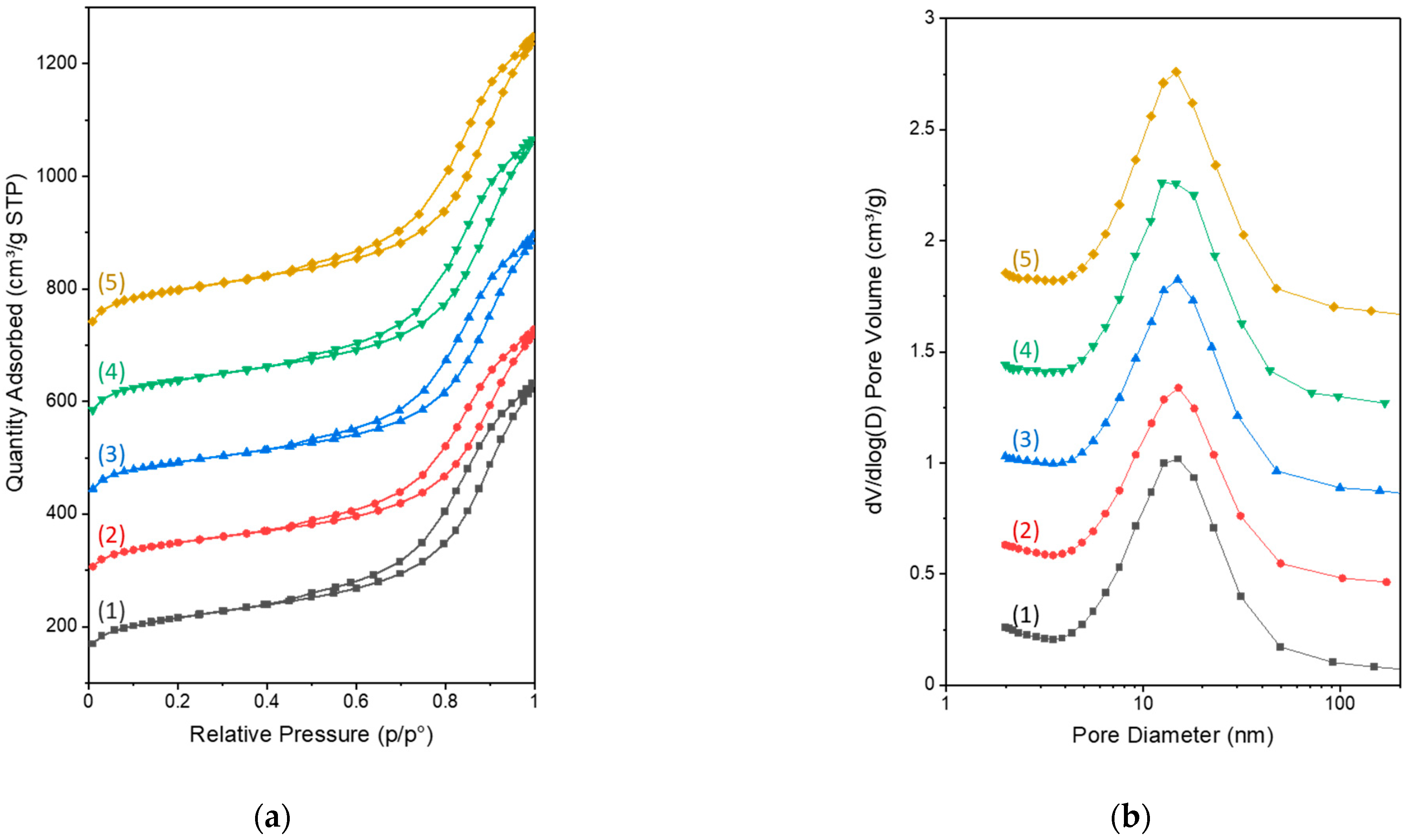
  31. Thommes, M.; Kaneko, K.; Neimark, A.V.; Olivier, J.P.; Rodriguez-Reinoso, F.; Rouquerol, J.; Sing, K.S.W. Physisorption of gases, with special reference to the evaluation of surface area and pore size distribution (IUPAC Technical Report). Pure Appl. Chem. 2015, 87, 1051–1069. [Google Scholar] [CrossRef] [Green Version]
  32. Arrigo, R.; Blume, R.; Streibel, V.; Genovese, C.; Roldan, A.; Schuster, M.E.; Ampelli, C.; Perathoner, S.; Velasco Vélez, J.J.; Hävecker, M.; et al. Dynamics at polarized carbon dioxide–iron oxyhydroxide interfaces unveil the origin of multicarbon product formation. ACS Catal. 2021, 12, 411–430. [Google Scholar] [CrossRef]
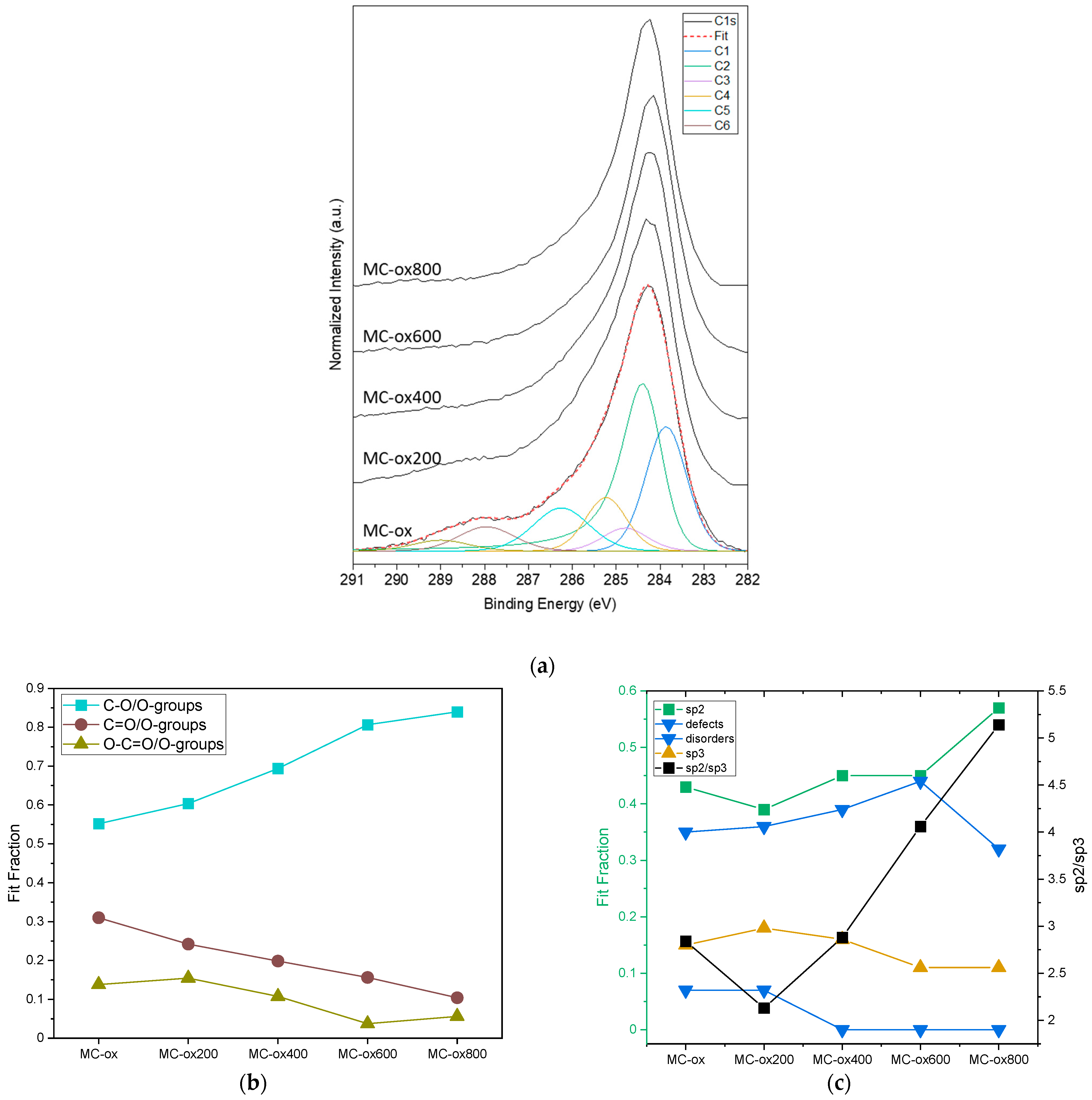
  33. Blume, R.; Rosenthal, D.; Tessonnier, J.-P.; Li, H.; Knop-Gericke, A.; Schlögl, R. Characterizing graphitic carbon with X-ray photoelectron spectroscopy: A step-by-step approach. ChemCatChem 2015, 7, 2871–2881. [Google Scholar] [CrossRef] [Green Version]
  34. Nikolov, P.Y.; Yaylayan, V.A. Thermal decomposition of 5-(hydroxymethyl)-2-furaldehyde (HMF) and its further transformations in the presence of glycine. J. Agric. Food Chem. 2011, 59, 10104–10113. [Google Scholar] [CrossRef]
  35. Zhao, M.; Li, B.; Cai, J.-X.; Liu, C.; McAdam, K.G.; Zhang, K. Thermal & chemical analyses of hydrothermally derived carbon materials from corn starch. Fuel Process. Technol. 2016, 153, 43–49. [Google Scholar] [CrossRef] [Green Version]
  36. Gerber, I.; Oubenali, M.; Bacsa, R.; Durand, J.; Gonçalves, A.; Pereira, M.F.R.; Jolibois, F.; Perrin, L.; Poteau, R.; Serp, P. Theoretical and Experimental Studies on the Carbon-Nanotube Surface Oxidation by Nitric Acid: Interplay between Functionalization and Vacancy Enlargement. Chem.–Eur. J. 2011, 17, 11467–11477. [Google Scholar] [CrossRef] [PubMed]
  37. Gomezserrano, V.; Acedoramos, M.; Lopezpeinado, A.; Valenzuelacalahorro, C. Oxidation of activated carbon by hydrogen peroxide. Study of surface functional groups by FT-i.r. Fuel 1994, 73, 387–395. [Google Scholar] [CrossRef]
  38. Eigler, S.; Dotzer, C.; Hirsch, A.; Enzelberger, M.; Müller, P. Formation and Decomposition of CO2 Intercalated Graphene Oxide. Chem. Mater. 2012, 24, 1276–1282. [Google Scholar] [CrossRef]
Figure 1. SEM images of HTC materials catalyzed using (a) hydrochloric acid, (b) formic acid, and (c) citric acid.
Carbon 08 00037 g001
Figure 2. Proposed structures for (a) as-synthesized HTC material and (b) mesoporous carbon from phenolic resin carbonized at 500 °C based on [25] and [26], respectively.
Carbon 08 00037 g002
Figure 3. Composition analysis of as-synthesized HTC and samples annealed at 200–800 °C showing a significant reduction in the oxygen content of the materials. Annealing was performed under a flow of nitrogen (200 mL/min) using a heat ramp of 10 °C/min and a dwell time of 1 h at the target temperature.
Carbon 08 00037 g003
Figure 4. SEM images of MC materials obtained from the carbonization of RF resin (EISA approach) showing the morphology and structure of these materials. (a) 5000× magnification image showing carbon aggregates; (b) 50,000× magnification image featuring meso- and macropores in the structure.
Carbon 08 00037 g004
Figure 5. Nitrogen physisorption analysis of MC-ox samples: (1) MC-ox, (2) MC-ox200, (3) MC-ox400, (4) MC-ox600, and (5) MC-ox800. (a) adsorption-desorption isotherms; offsets of 150, 275, 400, and 550 cm3/g were applied to the isotherms (2)–(5), respectively; (b) pore size distributions (PSD) calculated using the BJH model; a constant 0.4 cm3/g offset was applied between the PSDs.
Carbon 08 00037 g005
Figure 6. XPS analysis of the functionalized MC samples. (a) C1s spectra showing the peak deconvolution where defects (C1), graphitic sp2 (C2), disordered carbon (C3), sp3 (C4), C–O (C5), C=O (C6), O–C=O (C7) are considered in the fitting model (red dashed line shows the fit); (b) relative change in the composition of oxygen groups with increasing annealing temperature; (c) relative change in the composition of graphitic-sp2, defects, disordered, and sp3 carbon (■ represent the change in the ratio of graphitic-sp2/sp3 as a function of annealing temperature).
Carbon 08 00037 g006
Figure 7. TPD-MS analysis of functionalized MC samples: (a) CO2 profile (carboxylic acid: red and blue, anhydride: green); (b) CO profile (blue: hydroxyl/epoxy, green: aldehyde, purple: anhydride, golden: phenol).
Carbon 08 00037 g007
Figure 8. TEM images of supported palladium catalysts obtained with the functionalized MC supports: (a) Pd/MC-ox200; (b) Pd/MC-ox400; (c) Pd/MC-ox600; (d) Pd/MC-ox800.
Carbon 08 00037 g008
Table 1. Textural properties of HTC materials as a function of the annealing temperature.
SamplesAnnealing
Temperature
(°C)
Total
Surface Area
(m2/g)
Micropores
Surface
Area (m2/g)
Fraction of
Mesoporous
Surface Area
(%)
Average
Pore Size (nm) *
HTC-4---
HTC2002004.5---
HTC400400351263254.1
HTC60060044839511.75.1
HTC80080043839310.25.5
t-HTC800800531440 17.08.0
* Average pore sizes were calculated from the adsorption branch of the corresponding isotherms using the BJH model.
Table 2. Textural properties of the mesoporous carbons synthesized using the soft templated organic-organic self-assembly of resorcinol and formaldehyde in the presence of various acids.
CatalystBET
Surface Area
(m2/g)
BJH
Surface Area
(m2/g)
BJH
Pore Size
(nm)
BJH
Pore Volume
(cm3/g)
Micropore
Volume
(cm3/g)
Formic Acid5213796.10.5810.072
Citric Acid5013836.20.5890.059
Acetic Acid23611213.90.3890.041
Nitric Acid4552765.40.3720.076
Hydrochloric Acid57226314.50.7400.128
Average pore sizes were calculated from the adsorption branch of the corresponding isotherms using the BJH model.
Table 3. Elemental composition and textural properties of functionalized MC samples. MC-ox refers to the oxidized MC, which was subjected to an annealing step at temperatures between 200–800 °C.
CatalystAnnealing Temperature
(°C)
Elemental Composition (wt%)Surface
Area * (m2/g)
Average Pores Size (nm) *
NCHO
MC-ox-0.771.91.026.43229.9
MC-ox2002000.773.00.725.629010.0
MC-ox4004000.678.70.320.430310.1
MC-ox6006000.583.70.415.432510.1
MC-ox8008000.793.90.74.734010.1
* Average pore sizes and surface areas were calculated from the adsorption branch of the corresponding isotherms using the BJH model.
Table 4. Characteristics of the Pd/MC-ox catalysts.
CatalystAverage Pore Size
(nm) a
Pd
Loading
(wt.%) b
Metal
Dispersion
(%) c
Metallic Surface
Area (m2/g) c
Average Particle Size (nm) c
Pd/MC-ox2009.94.7633.87.1773.31
Pd/MC-ox40010.04.8033.47.1413.37
Pd/MC-ox6009.94.8232.46.9463.47
Pd/MC-ox8009.94.5531.66.4033.57
a Average pore sizes were calculated from the adsorption branch of the corresponding isotherms using the BJH model. b Pd loading was obtained from ICP-EOS analysis. c Metal dispersion, metallic surface area, and average particle size (hemisphere) were obtained using CO-chemisorption analysis.
Publisher’s Note: MDPI stays neutral with regard to jurisdictional claims in published maps and institutional affiliations.

