
In Silico Modelling to Assess the Electrical and Thermal Disturbance Provoked by a Metal Intracoronary Stent during Epicardial Pulsed Electric Field Ablation


Abstract
:1. Introduction
2. Methods
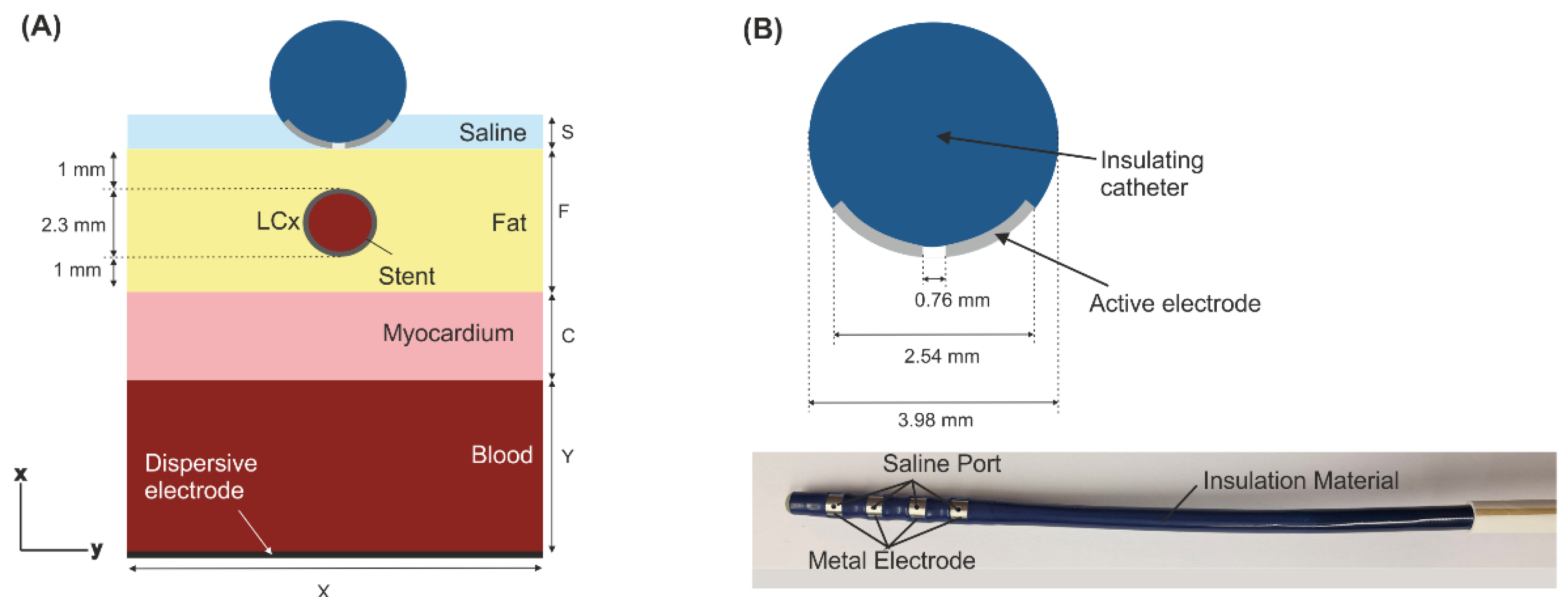
2.1. Model Geometry
2.2. Governing Equations
2.3. Material Properties
2.4. Boundary Conditions
2.5. Analysed Outcomes
3. Results
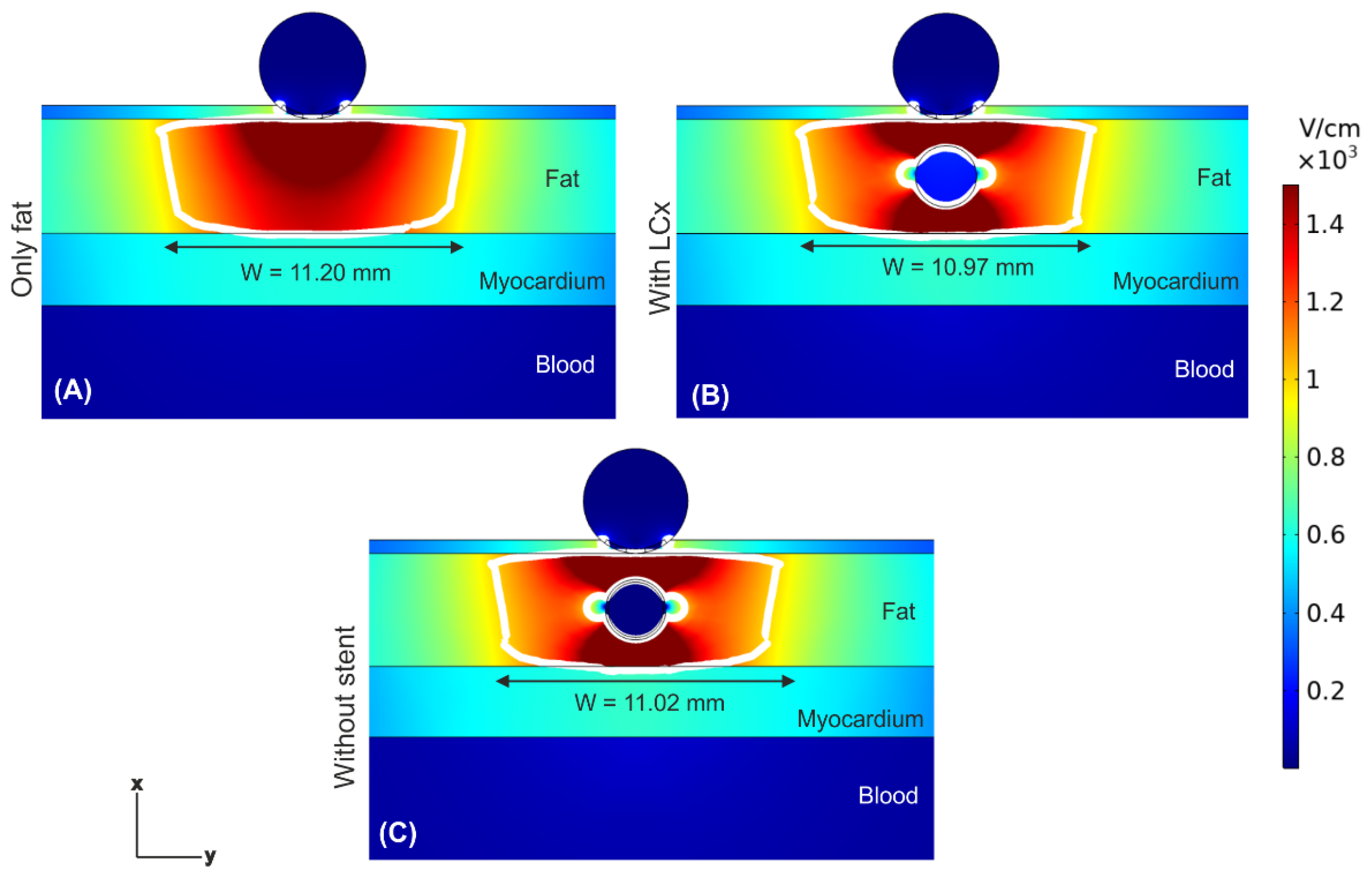
3.1. Electric Field Distribution
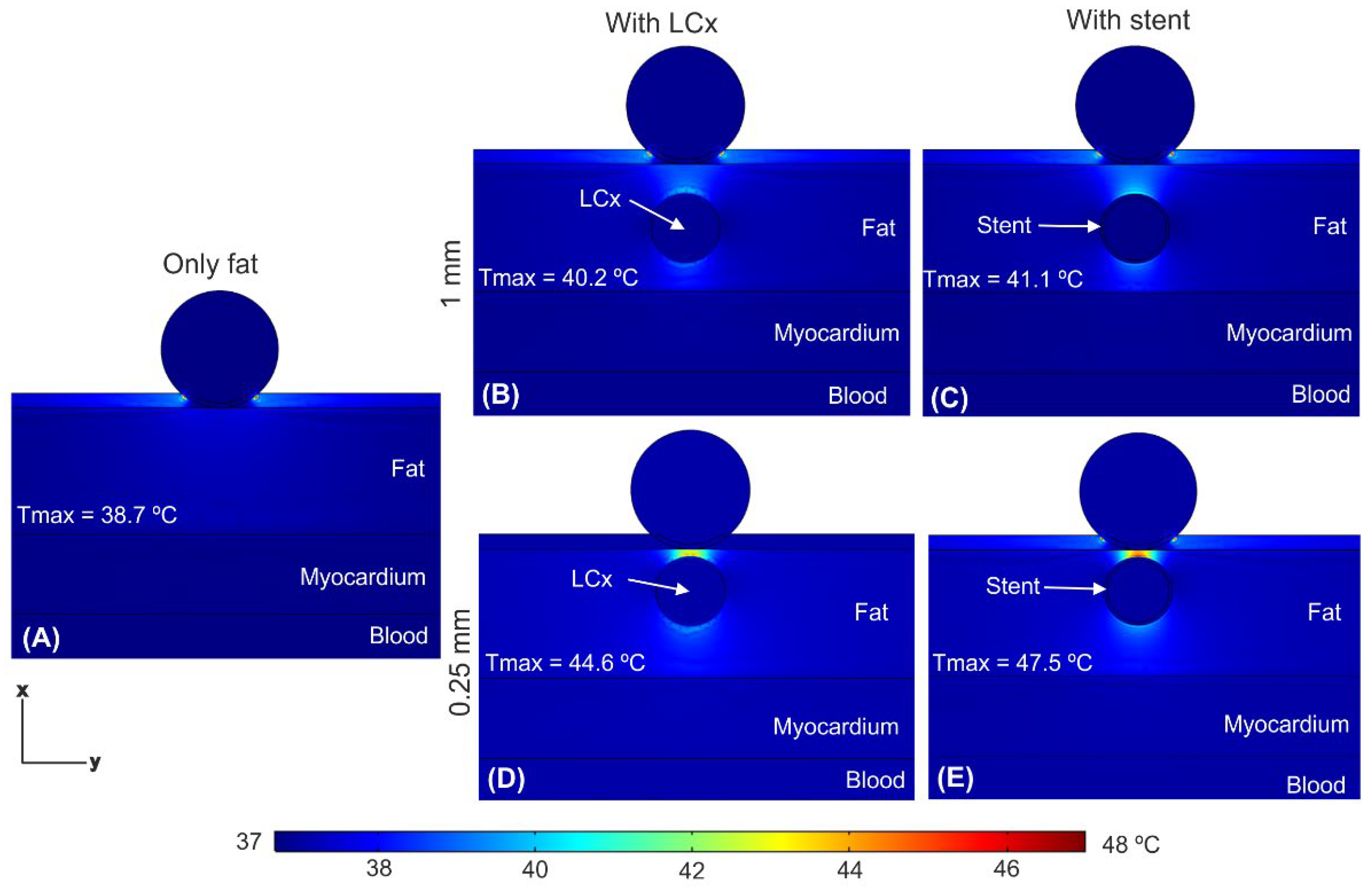
3.2. Temperature Distributions
4. Discussion
4.1. Main Findings
- (1)
- The presence of the coronary artery near the ablation electrode (with or without a stent) distorts the E-field distribution, creating hot spots (higher E-field values) in the front and rear of the artery, and cold spots (lower E-field values).
- (2)
- The value of E-field inside the coronary artery is very low (~200 V/cm), and almost zero in case with a metal stent.
- (3)
- Despite this distortion, the PEF-zone contour (assessed as the isoline of 1000 V/cm) is almost identical with and without artery/stent, remaining almost completely confined within the fat layer in any case.
- (4)
- The mentioned hot spots of E-field translate into a moderate temperature increase (<48 °C) in the area between artery and electrode.
- (5)
- The thermal distribution is similar for pulses intervals of 10 and 100 μs.
4.2. Limitations
5. Conclusions
Author Contributions
Funding
Institutional Review Board Statement
Informed Consent Statement
Data Availability Statement
Conflicts of Interest
References
- Padmanabhan, D.; Naksuk, N.; Killu, A.K.; Kapa, S.; Witt, C.; Sugrue, A.; DeSimone, C.V.; Madhavan, M.; de Groot, J.R.; O’Brien, B.; et al. Electroporation of epicardial autonomic ganglia: Safety and efficacy in medium-term canine models. J. Cardiovasc. Electrophysiol. 2019, 30, 607–615. [Google Scholar] [CrossRef] [PubMed]
- Madhavan, M.; Venkatachalam, K.L.; Swale, M.J.; Desimone, C.V.; Gard, J.J.; Johnson, S.B.; Suddendorf, S.H.; Mikell, S.B.; Ladewig, D.J.; Nosbush, T.G.; et al. Novel Percutaneous Epicardial Autonomic Modulation in the Canine for Atrial Fibrillation: Results of an Efficacy and Safety Study. Pacing Clin. Electrophysiol. 2016, 39, 407–417. [Google Scholar] [CrossRef] [PubMed] [Green Version]
- Avazzadeh, S.; McBride, S.; O’Brien, B.; Coffey, K.; Elahi, A.; O’Halloran, M.; Soo, A.; Quinlan, L.R. Ganglionated Plexi Ablation for the Treatment of Atrial Fibrillation. J. Clin. Med. 2020, 9, 3081. [Google Scholar] [CrossRef]
- González-Suárez, A.; O’Brien, B.; O’Halloran, M.; Elahi, A. Pulsed electric field ablation of epicardial autonomic ganglia: Computer analysis of monopolar electric field across the tissues involved. Bioengineering 2022, 9, 731. [Google Scholar] [CrossRef]
- Hogenes, A.M.; Slump, C.H.; Te Riet, O.G.; Scholten, G.A.; Meijerink, M.R.; Fütterer, J.J.; van Laarhoven, C.J.H.M.; Overduin, C.G.; Stommel, M.W.J. Effect of irreversible electroporation parameters and the presence of a metal stent on the electric field line pattern. Sci. Rep. 2020, 10, 13517. [Google Scholar] [CrossRef] [PubMed]
- Scheffer, H.J.; Vogel, J.A.; van den Bos, W.; Neal, R.E., 2nd; van Lienden, K.P.; Besselink, M.G.; van Gemert, M.J.; van der Geld, C.W.; Meijerink, M.R.; Klaessens, J.H.; et al. The Influence of a Metal Stent on the Distribution of Thermal Energy during Irreversible Electroporation. PLoS ONE 2016, 11, e0148457. [Google Scholar] [CrossRef] [PubMed]
- Scheffer, H.J.; Vogel, J.A.; van den Bos, W.; Meijerink, M.R.; Besselink, M.G.; Verdaasdonk, R.M.; Klaessens, J.; van der Geld, C.W.; van Gemert, M.J. Comment to: Månsson C, Nilsson A, Karlson B-M. Severe complications with irreversible electroporation of the pancreas in the presence of a metallic stent: A warning of a procedure that never should be performed. Acta Radiol. Open 2015, 4, 2058460115584111. [Google Scholar] [CrossRef]
- Iasiello, M.; Andreozzi, A.; Bianco, N.; Vafai, K. The porous media theory applied to radiofrequency catheter ablation. Int. J. Numer. Methods Heat Fluid Flow 2020, 30, 2669–2681. [Google Scholar] [CrossRef]
- Wang, S.; Vafai, K. Analysis of the effect of stent emplacement on LDL transport within an artery. Int. J. Heat Mass. Transf. 2013, 64, 1031–1040. [Google Scholar] [CrossRef]
- Sánchez-Quintana, D.; López-Mínguez, J.R.; Macías, Y.; Cabrera, J.A.; Saremi, F. Left atrial anatomy relevant to catheter ablation. Cardiol. Res. Pract. 2014, 2014, 289720. [Google Scholar] [CrossRef]
- González-Suárez, A.; Irastorza, R.M.; Deane, S.; O’Brien, B.; O’Halloran, M.; Elahi, A. Full torso and limited-domain computer model for epicardial pulsed electric field ablation. Comput. Methods Programs Biomed. 2022, 221, 106886. [Google Scholar] [CrossRef] [PubMed]
- Yokokawa, M.; Sundaram, B.; Garg, A.; Stojanovska, J.; Oral, H.; Morady, F.; Chugh, A. Impact of mitral isthmus anatomy on the likelihood of achieving linear block in patients undergoing catheter ablation of persistent atrial fibrillation. Heart Rhythm. 2011, 8, 1404–1410. [Google Scholar] [CrossRef] [PubMed]
- Saito, A.; Dai, Z.; Ono, M.; Kanie, T.; Takaoka, Y.; Mizuno, A.; Komiyama, N.; Asano, T. The relationship between coronary stent strut thickness and the incidences of clinical outcomes after drug-eluting stent implantation: A systematic review and meta-regression analysis. Catheter. Cardiovasc. Interv. 2022, 99, 575–582. [Google Scholar] [CrossRef] [PubMed]
- Sheehan, M.C.; Srimathveeravalli, G. Pulsed electric fields. Principles and Technologies for Electromagnetic Based Therapies. In Principles and Technologies for Electromagnetic Energy Based Therapies; Prakash, P., Srimathveeravalli, G., Eds.; Elsevier Academic Press: Cambridge, MA, USA, 2021; pp. 71–106. ISBN 9780128205945. [Google Scholar]
- Berjano, E.J. Theoretical modeling for radiofrequency ablation: State-of-the-art and challenges for the future. Biomed. Eng. Online 2006, 5, 24. [Google Scholar] [CrossRef] [PubMed] [Green Version]
- Pérez, J.J.; Ewertowska, E.; Berjano, E. Computer Modeling for Radiofrequency Bipolar Ablation Inside Ducts and Vessels: Relation Between Pullback Speed and Impedance Progress. Lasers Surg. Med. 2020, 52, 897–906. [Google Scholar] [CrossRef] [PubMed]
- Hasgall, P.A.; Di Gennaro, F.; Baumgartner, C.; Neufeld, E.; Lloyd, B.; Gosselin, M.C.; Payne, D.; Klingenböck, A.; Kuster, N. It Is Database for Thermal and Electromagnetic Parameters of Biological Tissues, Version 4.1, 22 February 2022. Available online: https://itis.swiss/virtual-population/tissue-properties/overview/ (accessed on 11 November 2022). [CrossRef]
- Gabriel, C.; Peyman, A.; Grant, E.H. Electrical conductivity of tissue at frequencies below 1 MHz. Phys. Med. Biol. 2009, 54, 4863–4878. [Google Scholar] [CrossRef]
- Gopalakrishnan, J.A. A mathematical model for irrigated epicardial radiofrequency ablation. Ann. Biomed. Eng. 2002, 30, 884–893. [Google Scholar] [CrossRef]
- Berjano, E.J.; Burdío, F.; Navarro, A.C.; Burdío, J.M.; Güemes, A.; Aldana, O.; Ros, P.; Sousa, R.; Lozano, R.; Tejero, E.; et al. Improved perfusion system for bipolar radiofrequency ablation of liver: Preliminary findings from a computer modelling study. Physiol. Meas. 2006, 27, N50–N66. [Google Scholar] [CrossRef]
- Sel, D.; Cukjati, D.; Batiuskaite, D.; Slivnik, T.; Mir, L.M.; Miklavcic, D. Sequential finite element model of tissue electropermeabilization. IEEE Trans. Biomed. Eng. 2005, 52, 816–827. [Google Scholar] [CrossRef]
- Castellví, Q.; Mecadal, B.; Moll, X.; Fondevila, D.; Andaluz, A.; Ivorra, A. Avoiding neuromuscular stimulation in liver irreversible electroporation using radiofrequency elect ric fields. Phys. Med. Biol. 2018, 63, 035027. [Google Scholar] [CrossRef] [Green Version]
- Suárez, A.G.; Hornero, F.; Berjano, E. Mathematical modeling of epicardial RF ablation of atrial tissue with overlying epicardial fat. Open Biomed. Eng. J. 2010, 4, 47–55. [Google Scholar] [CrossRef] [Green Version]
- Tungjitkusolmun, S.; Vorperian, V.R.; Bhavaraju, N.; Cao, H.; Tsai, J.Z.; Webster, J.G. Guidelines for predicting lesion size at common endocardial locations during radio-frequency ablation. IEEE Trans. Biomed. Eng. 2001, 48, 194–201. [Google Scholar] [CrossRef] [PubMed]
- González-Suárez, A.; Berjano, E. Comparative analysys of different methods of modeling the thermal effect of circulating blood flow during RF cardiac ablation. IEEE Trans. Biomed. Eng. 2016, 63, 250–259. [Google Scholar] [CrossRef] [PubMed] [Green Version]
- Anjaneyulu, A.; Raghu, K.; Chandramukhi, S.; Satyajit, G.M.; Arramraja, S.; Raghavaraju, P.; Krishnamraju, P.; Somaraju, B. Evaluation of left main coronary artery stenosis by transthoracic echocardiography. J. Am. Soc. Echocardiogr. 2008, 21, 855–860. [Google Scholar] [CrossRef] [PubMed]
- Stewart, M.T.; Haines, D.E.; Miklavčič, D.; Kos, B.; Kirchhof, N.; Barka, N.; Mattison, L.; Martien, M.; Onal, B.; Howard, B.; et al. Safety and chronic lesion characterization of pulsed field ablation in a Porcine model. J. Cardiovasc. Electrophysiol. 2021, 32, 958–969. [Google Scholar] [CrossRef]
- Avazzadeh, S.; O’Brien, B.; Coffey, K.; O’Halloran, M.; Keane, D.; Quinlan, L.R. Establishing irreversible electroporation electric field potential threshold in a suspension in vitro model for cardiac and neuronal cells. J. Clin. Med. 2021, 10, 5443. [Google Scholar] [CrossRef]
- Agnass, P.; van Veldhuisen, E.; Vogel, J.A.; Kok, H.P.; de Keijzer, M.J.; Schooneveldt, G.; de Haan, L.R.; Klaessens, J.H.; Scheffer, H.J.; Meijerink, M.R.; et al. Thermodynamic profiling during irreversible electroporation in porcine liver and pancreas: A case study series. J. Clin. Transl. Res. 2020, 5, 109–132. [Google Scholar]
- Castellví, Q.; Sánchez-Velázquez, P.; Berjano, E.; Burdío, F.; Ivorra, A. Selective Electroporation of Liver Tumor Nodules by Means of Hypersaline Infusion: A Feasibility Study. In IFMBE Proceedings, Proceedings of the 6th European Conference of the International Federation for Medical and Biological Engineering, Dubrovnik, Croatia, 7–11 September 2014; Lacković, I., Vasic, D., Eds.; Springer: Cham, Germany, 2015; Volume 45. [Google Scholar] [CrossRef] [Green Version]
- Haines, D.E. Letter by Haines regarding article: Direct measurement of the lethal isotherm for radiofrequency ablation of myocardial tissue. Circ. Arrhythm. Electrophysiol. 2011, 4, e67. [Google Scholar] [CrossRef] [Green Version]
- Irastorza, R.M.; d’Avila, A.; Berjano, E. Thermal latency adds to lesion depth after application of high-power short-duration radiofrequency energy: Results of a computer-modeling study. J. Cardiovasc. Electrophysiol. 2018, 29, 322–327. [Google Scholar] [CrossRef]


| Element/Material | σ0 (S/m) | σ1 (S/m) | k (W/m·K) | ρ (kg/m3) | c (J/kg·K) |
|---|---|---|---|---|---|
| Electrode/Pt-Ir | 4.6 × 10⁶ | 71 | 21,500 | 132 | |
| Catheter/Polyurethane | 10−5 | 23 | 1440 | 1050 | |
| Stent/Stainless Steel | 7.4 × 10⁶ | 15 | 8000 | 480 | |
| Saline | 1.392 | 0.628 | 980 | 4184 | |
| Fat | 0.0377 | 0.0438 | 0.21 | 911 | 2348 |
| Heart/myocardium | 0.0537 | 0.281 | 0.56 | 1081 | 3686 |
| Blood | 0.7 | 0.748 | 0.52 | 1050 | 3617 |
Publisher’s Note: MDPI stays neutral with regard to jurisdictional claims in published maps and institutional affiliations. |
© 2022 by the authors. Licensee MDPI, Basel, Switzerland. This article is an open access article distributed under the terms and conditions of the Creative Commons Attribution (CC BY) license (https://creativecommons.org/licenses/by/4.0/).
Share and Cite
González-Suárez, A.; Pérez, J.J.; O’Brien, B.; Elahi, A. In Silico Modelling to Assess the Electrical and Thermal Disturbance Provoked by a Metal Intracoronary Stent during Epicardial Pulsed Electric Field Ablation. J. Cardiovasc. Dev. Dis. 2022, 9, 458. https://doi.org/10.3390/jcdd9120458
González-Suárez A, Pérez JJ, O’Brien B, Elahi A. In Silico Modelling to Assess the Electrical and Thermal Disturbance Provoked by a Metal Intracoronary Stent during Epicardial Pulsed Electric Field Ablation. Journal of Cardiovascular Development and Disease. 2022; 9(12):458. https://doi.org/10.3390/jcdd9120458
Chicago/Turabian StyleGonzález-Suárez, Ana, Juan J. Pérez, Barry O’Brien, and Adnan Elahi. 2022. "In Silico Modelling to Assess the Electrical and Thermal Disturbance Provoked by a Metal Intracoronary Stent during Epicardial Pulsed Electric Field Ablation" Journal of Cardiovascular Development and Disease 9, no. 12: 458. https://doi.org/10.3390/jcdd9120458
APA StyleGonzález-Suárez, A., Pérez, J. J., O’Brien, B., & Elahi, A. (2022). In Silico Modelling to Assess the Electrical and Thermal Disturbance Provoked by a Metal Intracoronary Stent during Epicardial Pulsed Electric Field Ablation. Journal of Cardiovascular Development and Disease, 9(12), 458. https://doi.org/10.3390/jcdd9120458