
The Multi-Agentization of a Dual-Arm Nursing Robot Based on Large Language Models


Abstract

1. Introduction
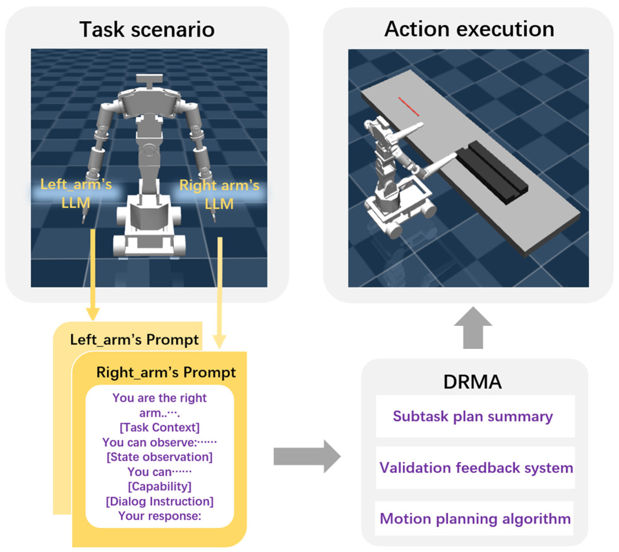
2. DRMA
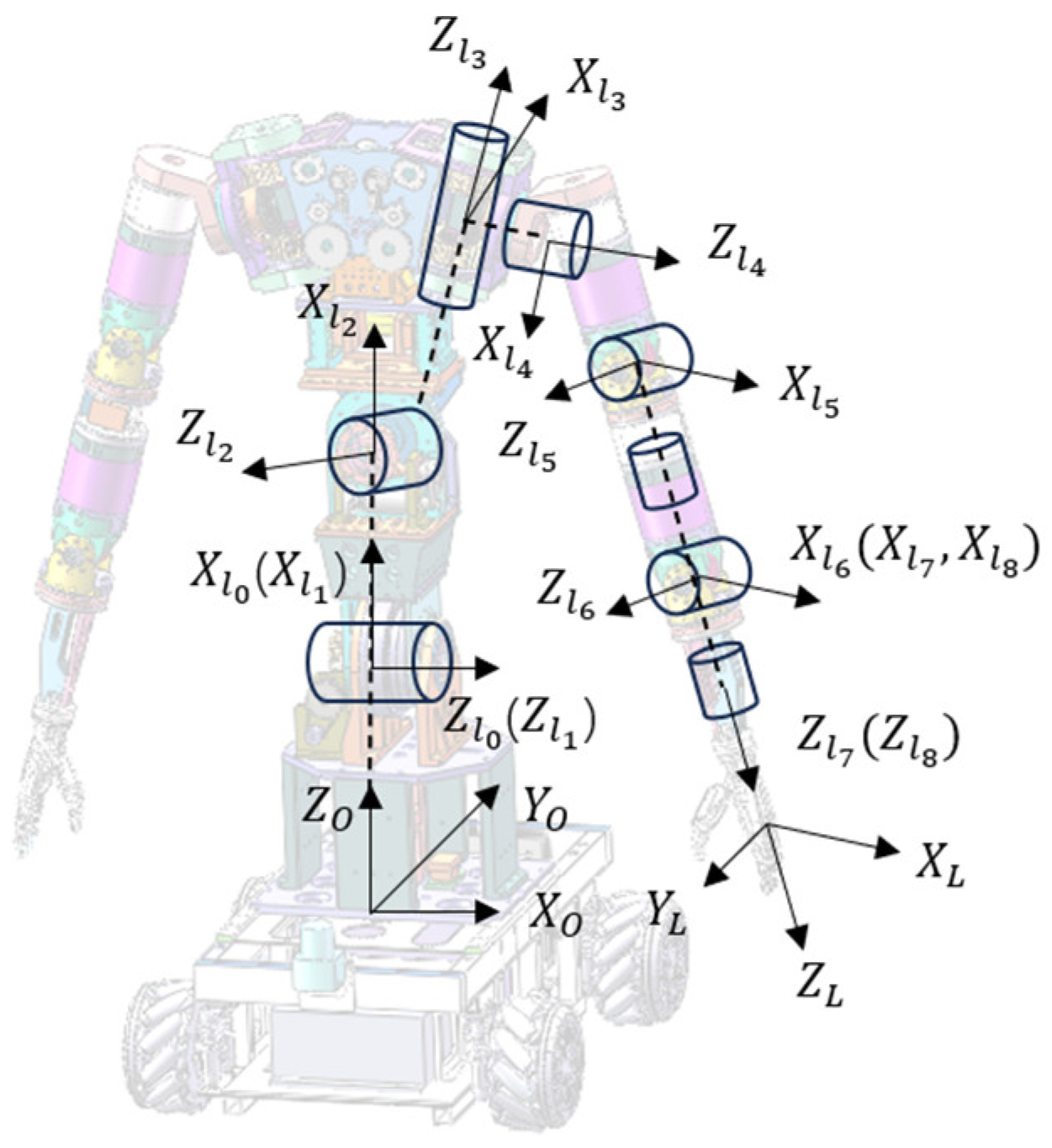
2.1. System Description
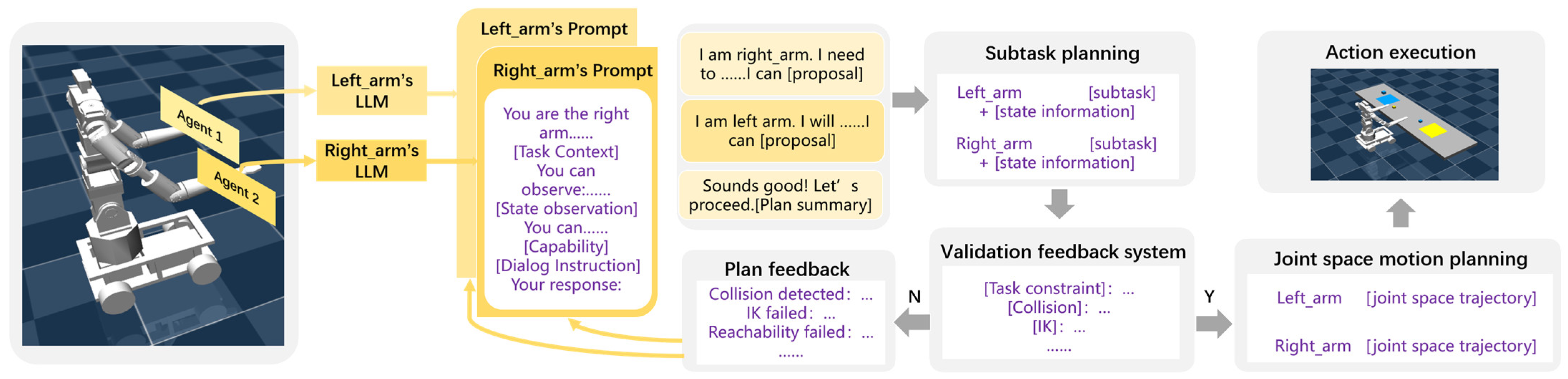
2.2. LLM-Driven Agent Dialogue Mechanism
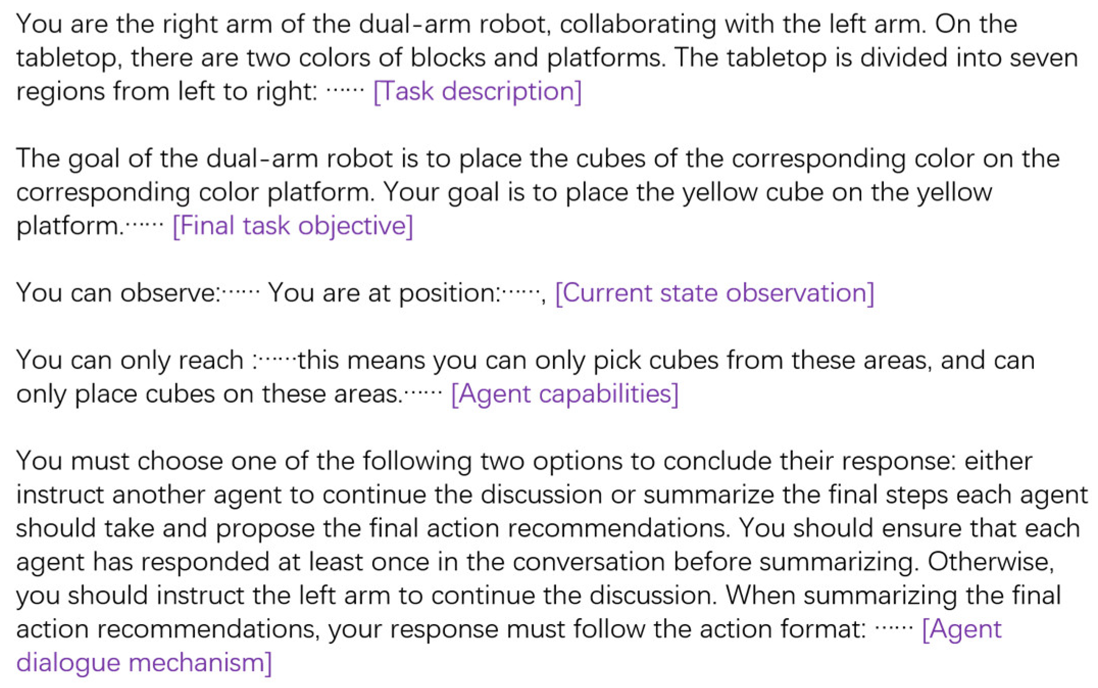
2.3. Prompt Engineering Design
2.4. Validation Feedback System Construction
| Algorithm 1: Multi-agent dialogue collaboration |
| Input:agent 1 , agent 2 , Execution time range T; Input:Maximum replanning iterationsK; Feedback history Fh; t = 0 = env.initialize() while t < T do Fh.clear_cache(); while len(Fh) < K do plan = PlanSolution(); valid_flag, feedback = validate_plan(plan) if valid_flag: executable_plan = plan; break end if Fh.apped(feedback); end while if valid_flag: = MotionPlanning(, executable_plan) = env.step(); if > 0: break end if end if t = t + 1 end while |
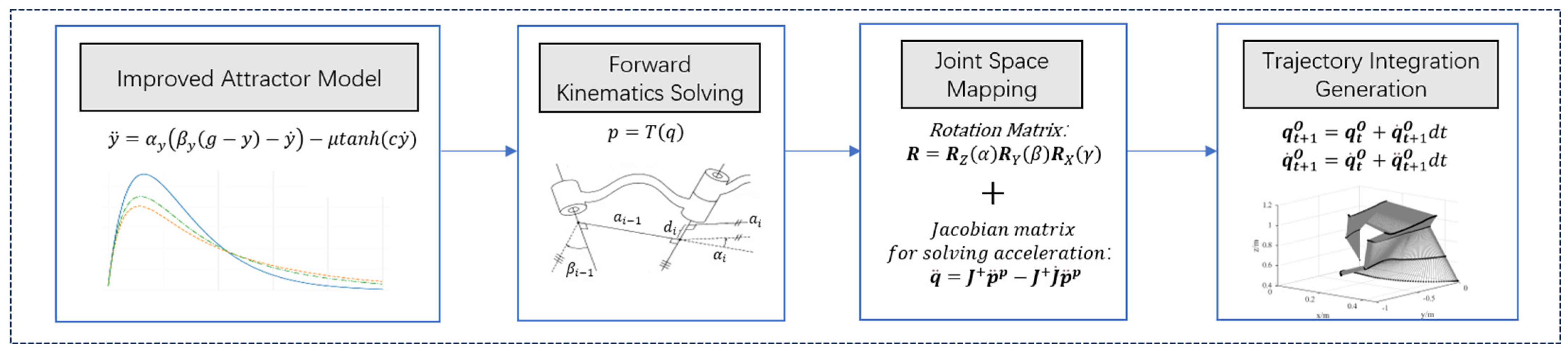
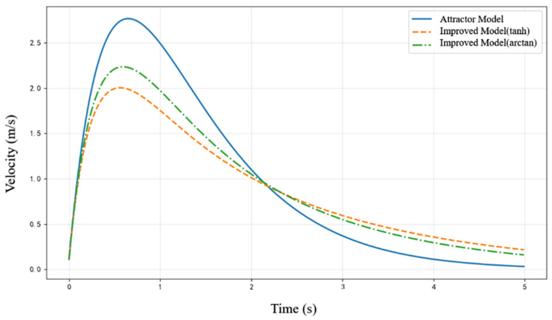
2.5. Motion Planning Algorithm Design
| Algorithm 2: Trajectory Planning Algorithm Based on the Improved Attractor Model |
| Input:Initial joint angles , Target pose g; Convergence threshold ε; Output:Planned trajectory Obtain initial state:End-effector pose: y = Forwardkinematics() End-effector velocity: Joint state: , while True do: Pose deviation:d = ComputeError (); Acceleration under attractor model: Constraint function term: F = LimitFunction () Attraction under improved attractor model: Pose acceleration mapped to joint space: Update if d < ε: break end if end while |
3. Experiments and Results
3.1. Experimental Setup
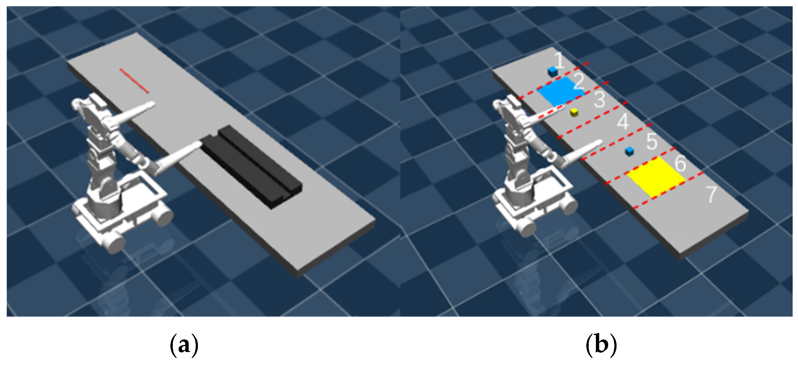
3.2. Task Scenarios
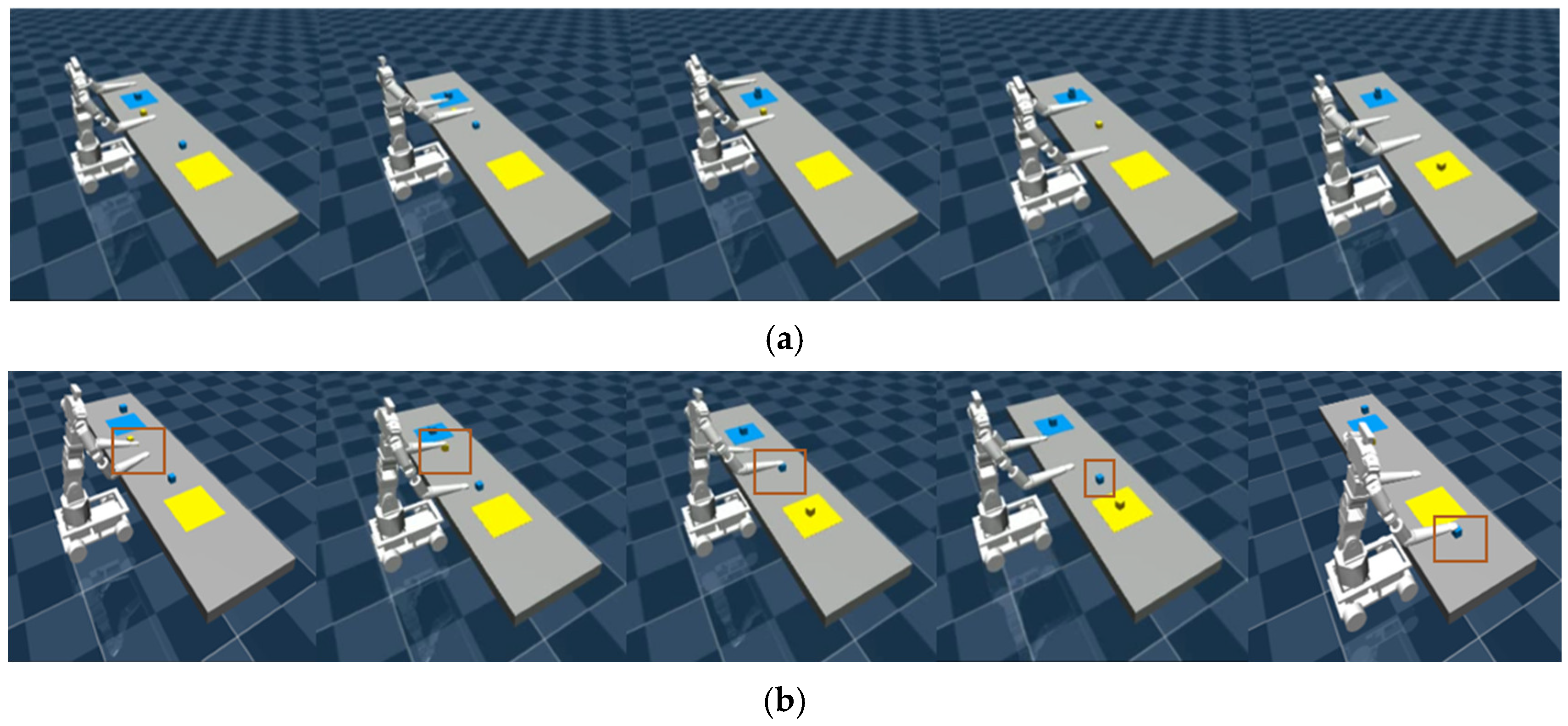
3.3. Task Planning Simulation Experiments
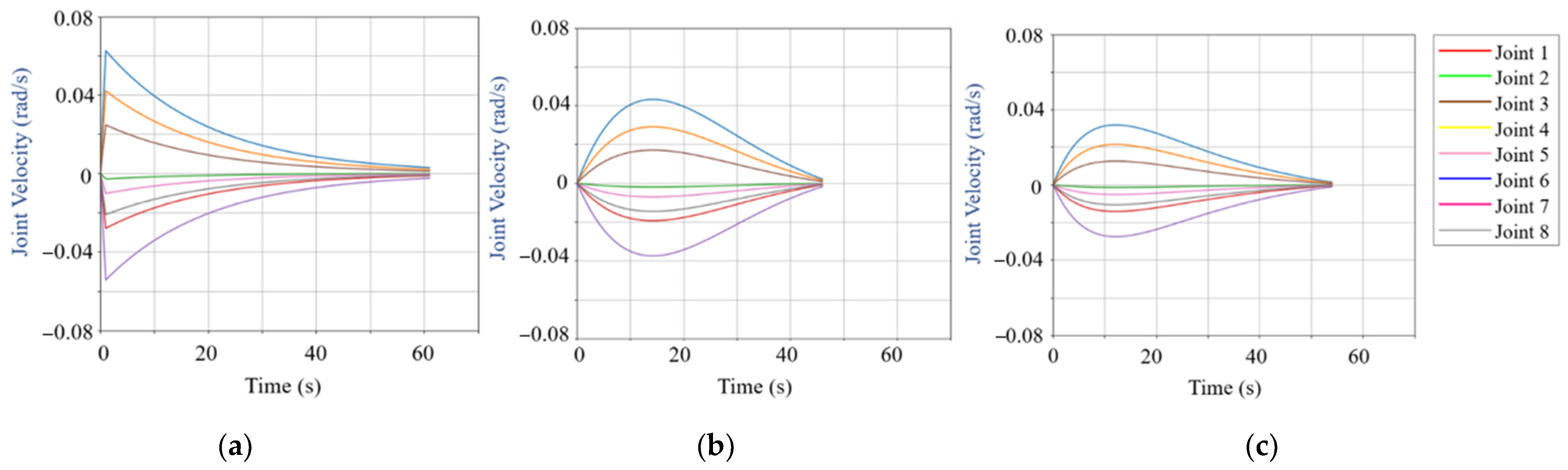
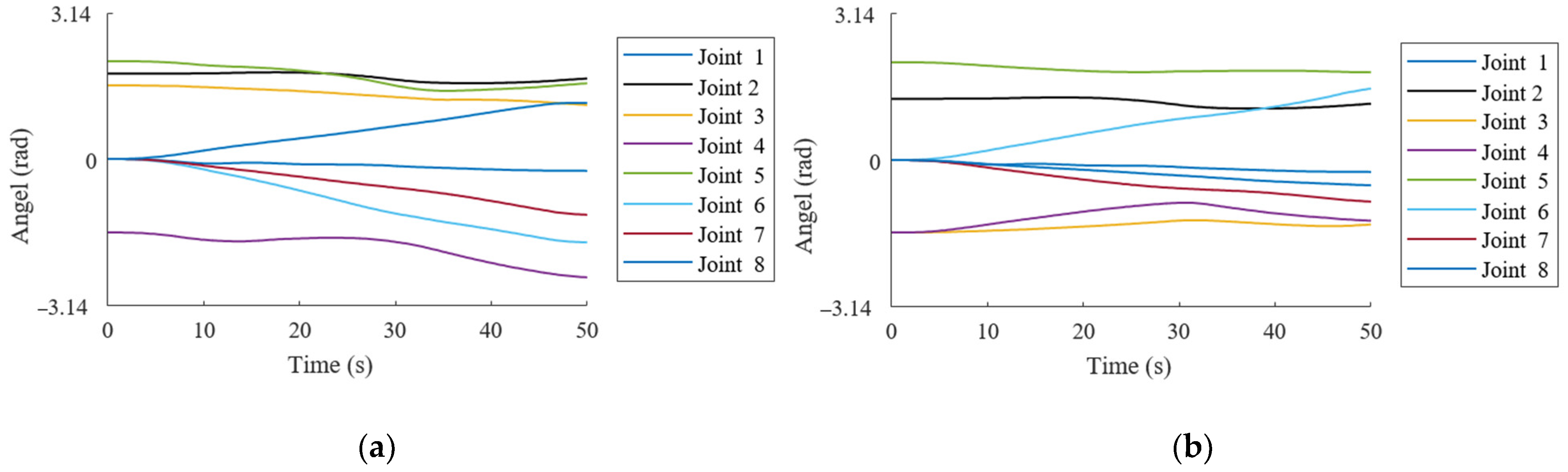
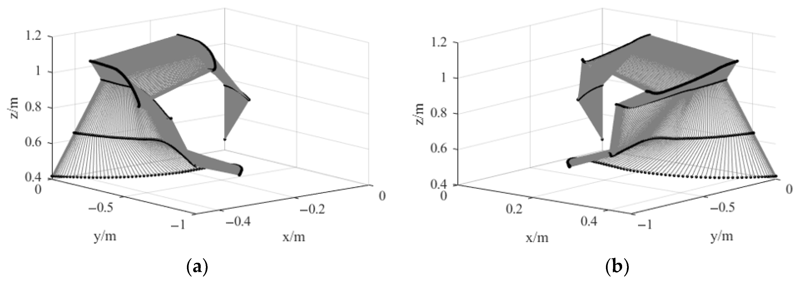
3.4. Trajectory Generation Simulation Experiments
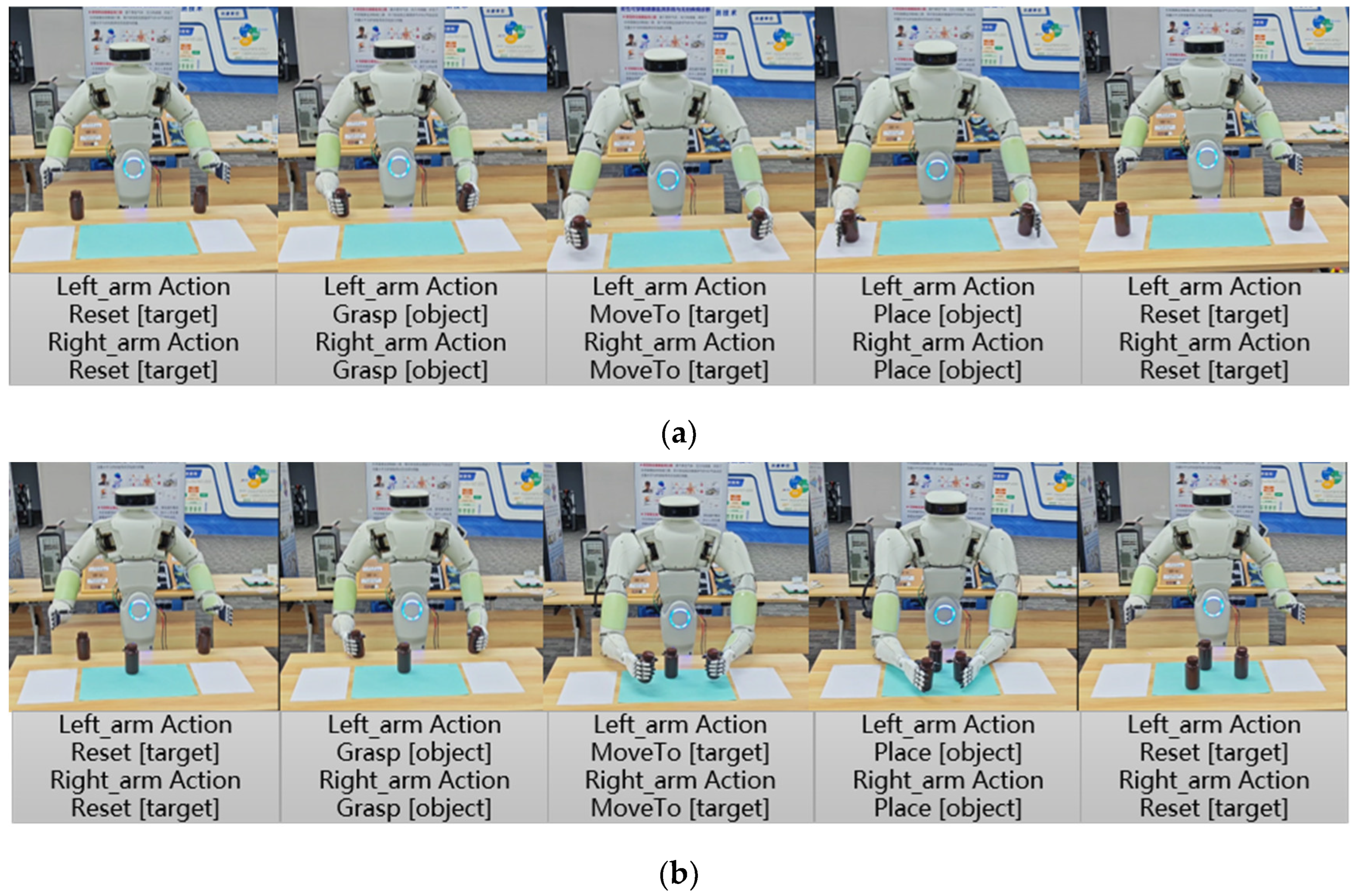
3.5. Real-World Experiments
4. Conclusions
Author Contributions
Funding
Institutional Review Board Statement
Informed Consent Statement
Data Availability Statement
Acknowledgments
Conflicts of Interest
References
- Bao, J.; Zhou, L.; Liu, G.; Tang, J.; Lu, X.; Cheng, C.; Jin, Y.; Bai, J. Current State of Care for the Elderly in China in the Context of an Aging Population. Biosci. Trends 2022, 16, 107–118. [Google Scholar] [CrossRef] [PubMed]
- Maalouf, N.; Sidaoui, A.; Elhajj, I.H.; Asmar, D. Robotics in Nursing: A Scoping Review. J. Nurs. Scholarsh. 2018, 50, 590–600. [Google Scholar] [CrossRef] [PubMed]
- Soriano, G.P.; Yasuhara, Y.; Ito, H.; Matsumoto, K.; Osaka, K.; Kai, Y.; Locsin, R.; Schoenhofer, S.; Tanioka, T. Robots and Robotics in Nursing. Healthcare 2022, 10, 1571. [Google Scholar] [CrossRef]
- Jiang, J.; Huang, Z.; Huo, B.; Zhang, Y.; Song, S. Research Progress and Prospect of Nursing Robot. Recent Pat. Mech. Eng. 2018, 11, 41–57. [Google Scholar] [CrossRef]
- Yang, Z.; Lu, H.; Chen, M.; Guan, Q.; Liu, Q.; Guo, S. Human-Robot Mechanics Model Using Hip Torque Identification with a Dual-Arm Nursing-Care Transfer Robot. Int. J. Adv. Robot. Syst. 2024, 21, 17298806241249848. [Google Scholar] [CrossRef]
- Zhao, D.; Sun, X.; Shan, B.; Yang, Z.; Yang, J.; Liu, H.; Jiang, Y.; Yokoi, H. Research Status of Elderly-Care Robots and Safe Human-Robot Interaction Methods. Front. Neurosci. 2023, 17, 1291682. [Google Scholar] [CrossRef]
- D’Ago, G.; Selvaggio, M.; Suarez, A.; Gańán, F.J.; Buonocore, L.R.; Di Castro, M.; Lippiello, V.; Ollero, A.; Ruggiero, F. Modelling and Identification Methods for Simulation of Cable-Suspended Dual-Arm Robotic Systems. Robot. Auton. Syst. 2024, 175, 104643. [Google Scholar] [CrossRef]
- Li, Y.; Guo, S.; Gan, Z. Empirical Prior Based Probabilistic Inference Neural Network for Policy Learning. Inf. Sci. 2022, 615, 678–699. [Google Scholar] [CrossRef]
- Li, J.; Wang, C.; Deng, H. Hybrid Nursing Robot Based on Humanoid Pick-Up Action: Safe Transfers in Living Environments for Lower Limb Disabilities. Actuators 2023, 12, 438. [Google Scholar] [CrossRef]
- Zhang, L.; Wang, S.; Miao, X. Workspace Simulation and Analysis of a Dual-Arm Nursing Robot. In Proceedings of the 12th International Conference on Intelligent Robotics and Applications (ICIRA 2019), Shenyang, China, 8–11 August 2019; Part VI. pp. 26–34. [Google Scholar] [CrossRef]
- Vaswani, A.; Shazeer, N.; Parmar, N.; Uszkoreit, J.; Jones, L.; Gomez, A.N.; Kaiser, Ł.; Polosukhin, I. Attention is All you Need. In Proceedings of the Advances in Neural Information Processing Systems, Long Beach, CA, USA, 4–9 December 2017; Volume 30. [Google Scholar] [CrossRef]
- Devlin, J.; Chang, M.W.; Lee, K.; Toutanova, K. BERT: Pre-training of Deep Bidirectional Transformers for Language Understanding. In Proceedings of the 2019 Conference of the North American Chapter of the Association for Computational Linguistics: Human Language Technologies (NAACL-HLT), Minneapolis, MN, USA, 2–7 June 2019; pp. 4171–4186. [Google Scholar] [CrossRef]
- Chowdhery, A.; Narang, S.; Devlin, J.; Bosma, M.; Mishra, G.; Roberts, A.; Barham, P.; Chung, H.W.; Sutton, C.; Gehrmann, S.; et al. PaLM: Scaling Language Modeling with Pathways. J. Mach. Learn. Res. 2023, 24, 1–113. [Google Scholar] [CrossRef]
- Ahn, M.; Brohan, A.; Brown, N.; Chebotar, Y.; Cortes, O.; David, B.; Finn, C.; Fu, C.; Gopalakrishnan, K.; Hausman, K.; et al. Do as I Can, Not as I Say: Grounding Language in Robotic Affordances. arXiv 2022, arXiv:2204.01691. [Google Scholar] [CrossRef]
- Wu, J.; Antonova, R.; Kan, A.; Lepert, M.; Zeng, A.; Song, S.; Bohg, J.; Rusinkiewicz, S.; Funkhouser, T. TidyBot: Personalized Robot Assistance with Large Language Models. Auton. Robot. 2023, 47, 1087–1102. [Google Scholar] [CrossRef]
- Wu, J.; Chong, W.; Holmberg, R.; Prasad, A.; Gao, Y.; Khatib, O.; Song, S.; Rusinkiewicz, S.; Bohg, J. TidyBot++: An Open-Source Holonomic Mobile Manipulator for Robot Learning. arXiv 2024, arXiv:2412.10447. [Google Scholar] [CrossRef]
- Huang, W.; Wang, C.; Zhang, R.; Li, Y.; Wu, J.; Fei-Fei, L. Voxposer: Composable 3D Value Maps for Robotic Manipulation with Language Models. arXiv 2023, arXiv:2307.05973. [Google Scholar] [CrossRef]
- Brown, T.; Mann, B.; Ryder, N.; Subbiah, M.; Kaplan, J.D.; Dhariwal, P.; Neelakantan, A.; Shyam, P.; Sastry, G.; Askell, A.; et al. Language Models are Few-Shot Learners. Adv. Neural Inf. Process. Syst. 2020, 33, 1877–1901. [Google Scholar] [CrossRef]
- Wei, J.; Wang, X.; Schuurmans, D.; Bosma, M.; Xia, F.; Chi, E.; Le, Q.V.; Zhou, D. Chain-of-Thought Prompting Elicits Reasoning in Large Language Models. Adv. Neural Inf. Process. Syst. 2022, 35, 24824–24837. [Google Scholar] [CrossRef]
- Singh, I.; Blukis, V.; Mousavian, A.; Goyal, A.; Xu, D.; Tremblay, J.; Fox, D.; Thomason, J.; Garg, A. ProgPrompt: Generating Situated Robot Task Plans Using Large Language Models. In Proceedings of the 2023 IEEE International Conference on Robotics and Automation (ICRA), London, UK, 29 May–2 June 2023; pp. 11523–11530. [Google Scholar] [CrossRef]
- Liang, J.; Huang, W.; Xia, F.; Xu, P.; Hausman, K.; Ichter, B.; Florence, P.; Zeng, A. Code as Policies: Language Model Programs for Embodied Control. In Proceedings of the 2023 IEEE International Conference on Robotics and Automation (ICRA), London, UK, 29 May–2 June 2023; pp. 9493–9500. [Google Scholar] [CrossRef]
- Chen, M.; Tworek, J.; Jun, H.; Yuan, Q.; Pinto, H.P.D.O.; Kaplan, J.; Edwards, H.; Burda, Y.; Joseph, N.; Brockman, G.; et al. Evaluating Large Language Models Trained on Code. arXiv 2021, arXiv:2107.03374. [Google Scholar] [CrossRef]
- Mandi, Z.; Jain, S.; Song, S. Roco: Dialectic Multi-Robot Collaboration with Large Language Models. In Proceedings of the 2024 IEEE International Conference on Robotics and Automation (ICRA), Osaka, Japan, 2–6 June 2024; pp. 286–299. [Google Scholar] [CrossRef]
- Liang, T.; He, Z.; Jiao, W.; Wang, X.; Wang, Y.; Wang, R.; Yang, Y.; Shi, S.; Tu, Z. Encouraging Divergent Thinking in Large Language Models through Multi-Agent Debate. arXiv 2023, arXiv:2305.19118. [Google Scholar] [CrossRef]
- Chatzea, V.E.; Logothetis, I.; Kalogiannakis, M.; Rovithis, M.; Vidakis, N. Digital Educational Tools for Undergraduate Nursing Education: A Review of Serious Games, Gamified Applications and Non-Gamified Virtual Reality Simulations/Tools for Nursing Students. Information 2024, 15, 410. [Google Scholar] [CrossRef]
- Li, G.; Hammoud, H.; Itani, H.; Khizbullin, D.; Ghanem, B. CAMEL: Communicative Agents for “Mind” Exploration of Large Language Model Society. Adv. Neural Inf. Process. Syst. 2023, 36, 51991–52008. [Google Scholar] [CrossRef]
- Chan, C.M.; Chen, W.; Su, Y.; Yu, J.; Xue, W.; Zhang, S.; Fu, J.; Liu, Z. Chateval: Towards Better LLM-Based Evaluators through Multi-Agent Debate. arXiv 2023, arXiv:2308.07201. [Google Scholar] [CrossRef]
- Schaal, S.; Peters, J.; Nakanishi, J.; Ijspeert, A. Control, Planning, Learning, and Imitation with Dynamic Movement Primitives. In Proceedings of the Workshop on Bilateral Paradigms on Humans and Humanoids: IEEE International Conference on Intelligent Robots and Systems (IROS), Las Vegas, NV, USA, 27–31 October 2003; pp. 1–21. [Google Scholar]
- GLM Team; Zeng, A.; Xu, B.; Wang, B.; Zhang, C.; Yin, D.; Zhang, D.; Rojas, D.; Feng, G.; Zhao, H.; et al. ChatGLM: A Family of Large Language Models from GLM-130B to GLM-4 All Tools. arXiv 2024, arXiv:2406.12793. [Google Scholar] [CrossRef]
- Lu, S.; Li, Y.; Ding, B. Kinematics and Dynamics Analysis of the 3 P US-P RU Parallel Mechanism Module Designed for a Novel 6-DOF Gantry Hybrid Machine Tool. J. Mech. Sci. Technol. 2020, 34, 345–357. [Google Scholar] [CrossRef]
- Lu, S.; Ding, B.; Li, Y. Minimum-Jerk Trajectory Planning Pertaining to a Translational 3-Degree-of-Freedom Parallel Manipulator through Piecewise Quintic Polynomials Interpolation. Adv. Mech. Eng. 2020, 12, 1687814020913667. [Google Scholar] [CrossRef]


| Verification Content | Description |
|---|---|
| Task Format Validation | Ensures task plan format compliance and execution-round alignment. |
| Task–Capability Validation | Validates task alignment with agent capabilities. |
| Safety Validation | Checks posture achievability via inverse kinematics and collision risks during execution. |
| Component | Configuration Information |
|---|---|
| Operating System | Windows 11 |
| CPU | AMD Ryzen 9 5900HX |
| GPU | NVIDIA GeForce RTX 3090 |
| RAM | 32 GB |
| Programming Language | Python 3.8.18 |
| 0 | 0 | 0 | ||
| 0 | − | |||
| 0 | ||||
| 0 | ||||
| 0 | ||||
| 0 | 0 | − | ||
| 0 |
| Task Type | Agent Mode | Feedback Used | ASR | ANS | ANP |
|---|---|---|---|---|---|
| Placing the Rope | Single-Agent | Yes | 90% | 3.2 | 5.2 |
| Placing the Rope | Single-Agent | No | 70% | 4.6 | 4.6 |
| Placing the Rope | DRMA | Yes | 100% | 2.4 | 2.9 |
| Placing the Rope | DRMA | No | 80% | 3.8 | 3.8 |
| Organizing Blocks | Single-Agent | Yes | 70% | 7.1 | 12.0 |
| Organizing Blocks | Single-Agent | No | 20% | 9.3 | 9.3 |
| Organizing Blocks | DRMA | Yes | 70% | 6.5 | 6.8 |
| Organizing Blocks | DRMA | No | 70% | 6.9 | 6.9 |
| Task Type | Agent Mode | ASR | ANS | ANP | AET |
|---|---|---|---|---|---|
| Bottle Sorting Task 1 | Single-Agent | 100% | 6.8 | 7.8 | 216.86 s |
| Bottle Sorting Task 1 | DRMA | 100% | 5.0 | 5.7 | 157.46 s |
| Bottle Sorting Task 2 | Single-Agent | 90% | 7.3 | 8.9 | 228.61 s |
| Bottle Sorting Task 2 | DRMA | 100% | 5.0 | 5.8 | 162.32 s |
Disclaimer/Publisher’s Note: The statements, opinions and data contained in all publications are solely those of the individual author(s) and contributor(s) and not of MDPI and/or the editor(s). MDPI and/or the editor(s) disclaim responsibility for any injury to people or property resulting from any ideas, methods, instructions or products referred to in the content. |
© 2025 by the authors. Licensee MDPI, Basel, Switzerland. This article is an open access article distributed under the terms and conditions of the Creative Commons Attribution (CC BY) license (https://creativecommons.org/licenses/by/4.0/).
Share and Cite
Fang, C.; Yue, X.; Zhao, Z.; Guo, S. The Multi-Agentization of a Dual-Arm Nursing Robot Based on Large Language Models. Bioengineering 2025, 12, 448. https://doi.org/10.3390/bioengineering12050448
Fang C, Yue X, Zhao Z, Guo S. The Multi-Agentization of a Dual-Arm Nursing Robot Based on Large Language Models. Bioengineering. 2025; 12(5):448. https://doi.org/10.3390/bioengineering12050448
Chicago/Turabian StyleFang, Chuanhong, Xiaotian Yue, Zhendong Zhao, and Shijie Guo. 2025. "The Multi-Agentization of a Dual-Arm Nursing Robot Based on Large Language Models" Bioengineering 12, no. 5: 448. https://doi.org/10.3390/bioengineering12050448
APA StyleFang, C., Yue, X., Zhao, Z., & Guo, S. (2025). The Multi-Agentization of a Dual-Arm Nursing Robot Based on Large Language Models. Bioengineering, 12(5), 448. https://doi.org/10.3390/bioengineering12050448