
Personalized Stem Length Optimization in Hip Replacement: A Microscopic Perspective on Bone—Implant Interaction


Abstract

1. Introduction
2. Materials and Methods
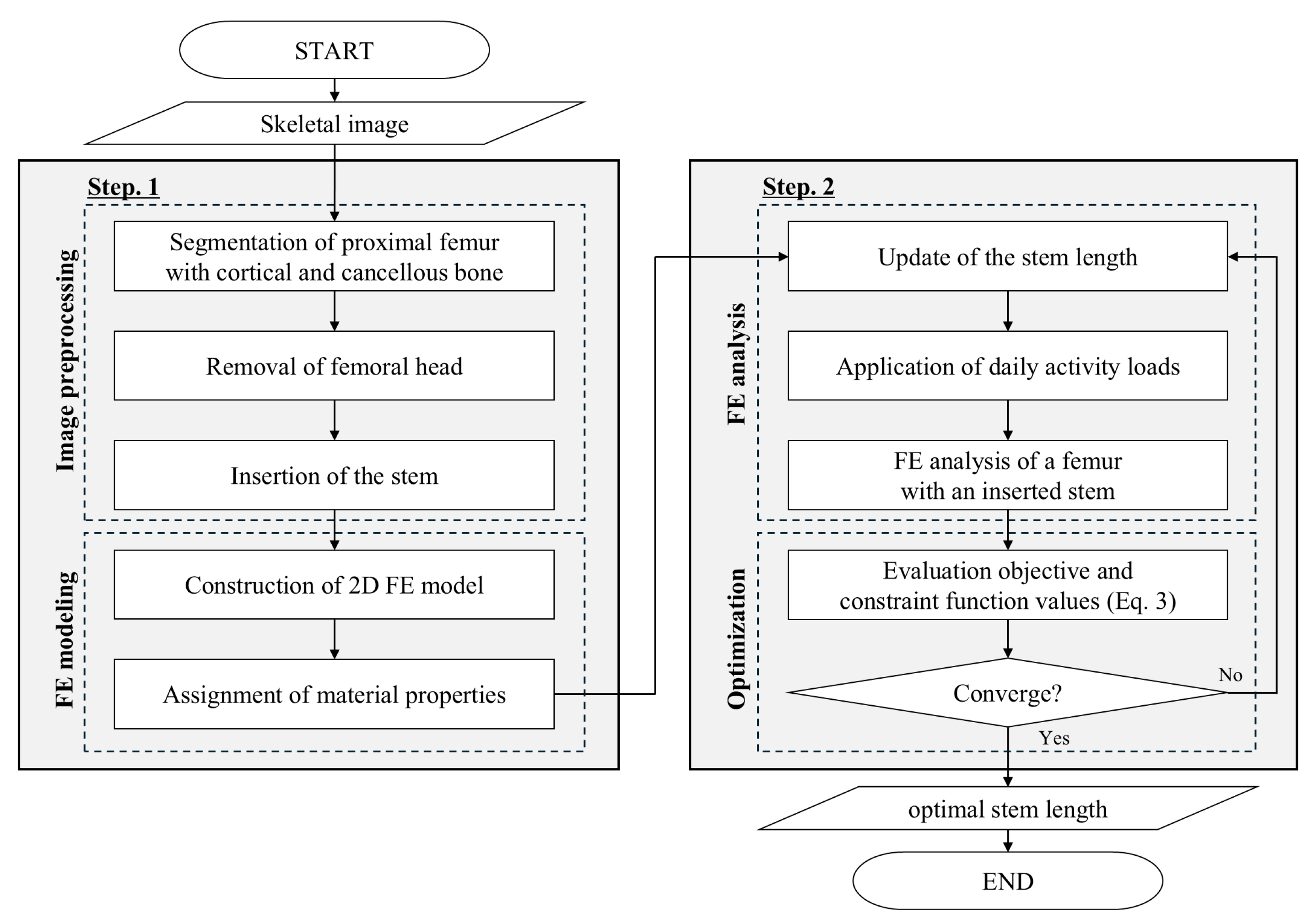
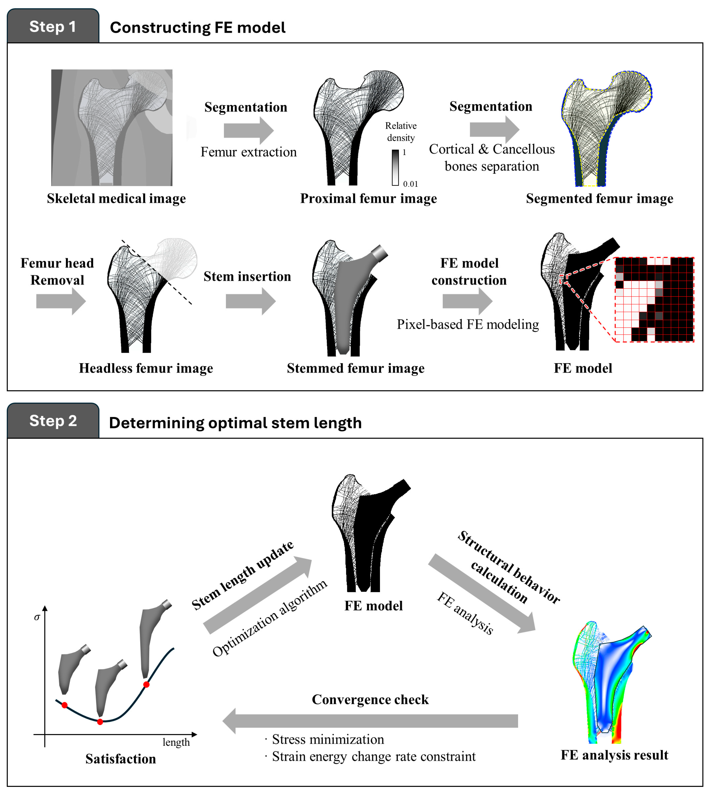
2.1. Procedure for the Proposed Stem Length Optimization
2.1.1. Finite Element Modeling
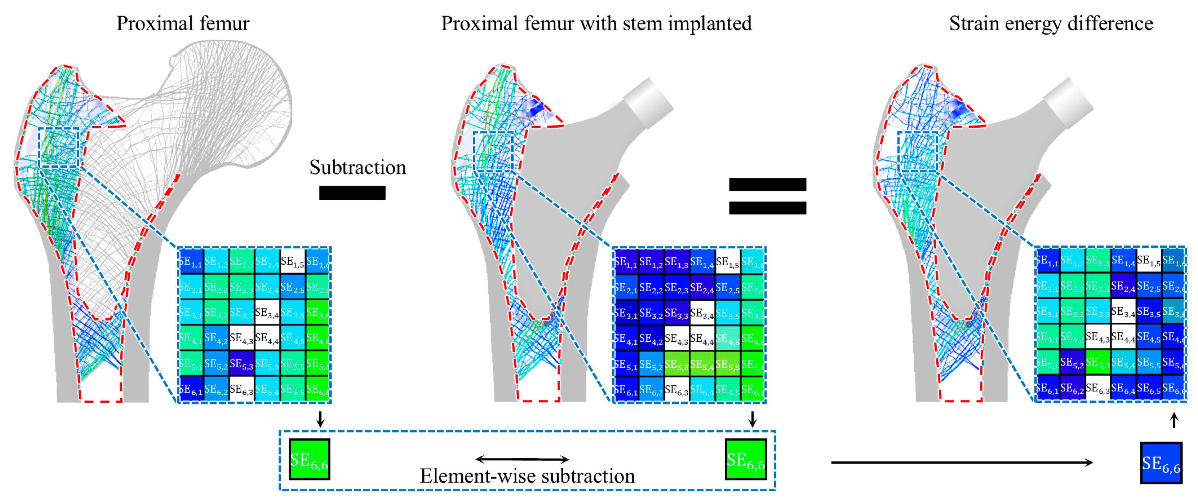
2.1.2. Optimal Stem Length Determination
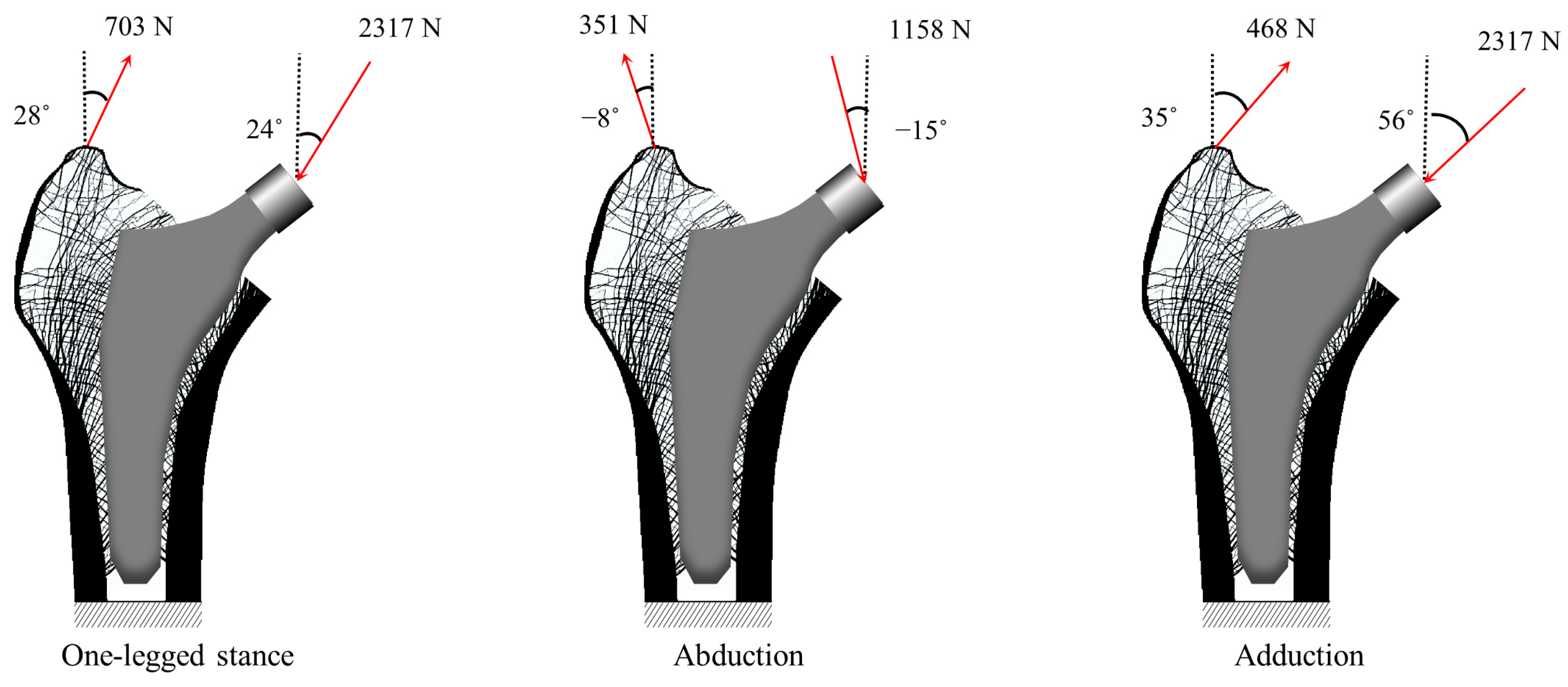
2.2. Numerical Example for Validation
2.3. Compared Study
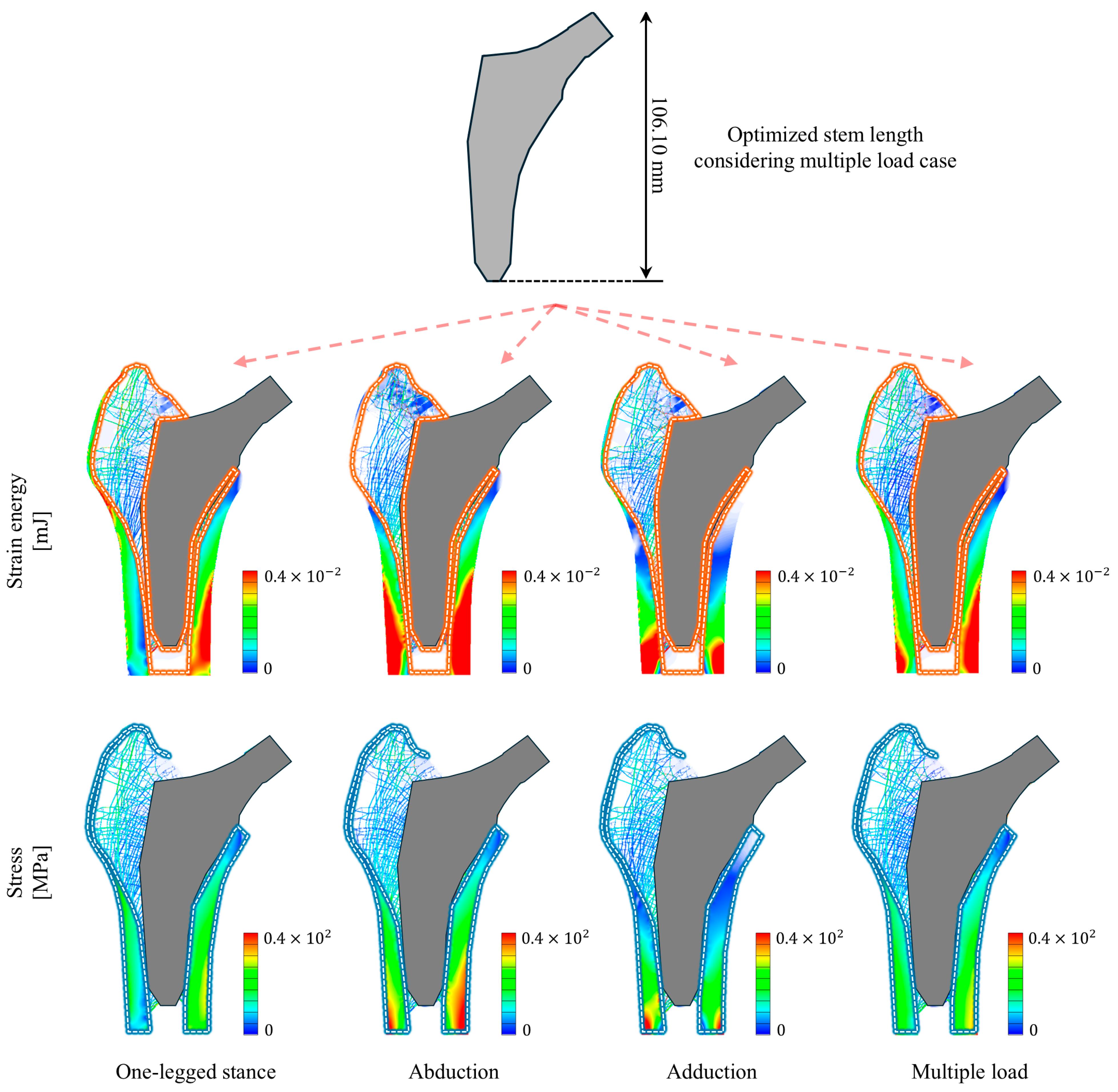
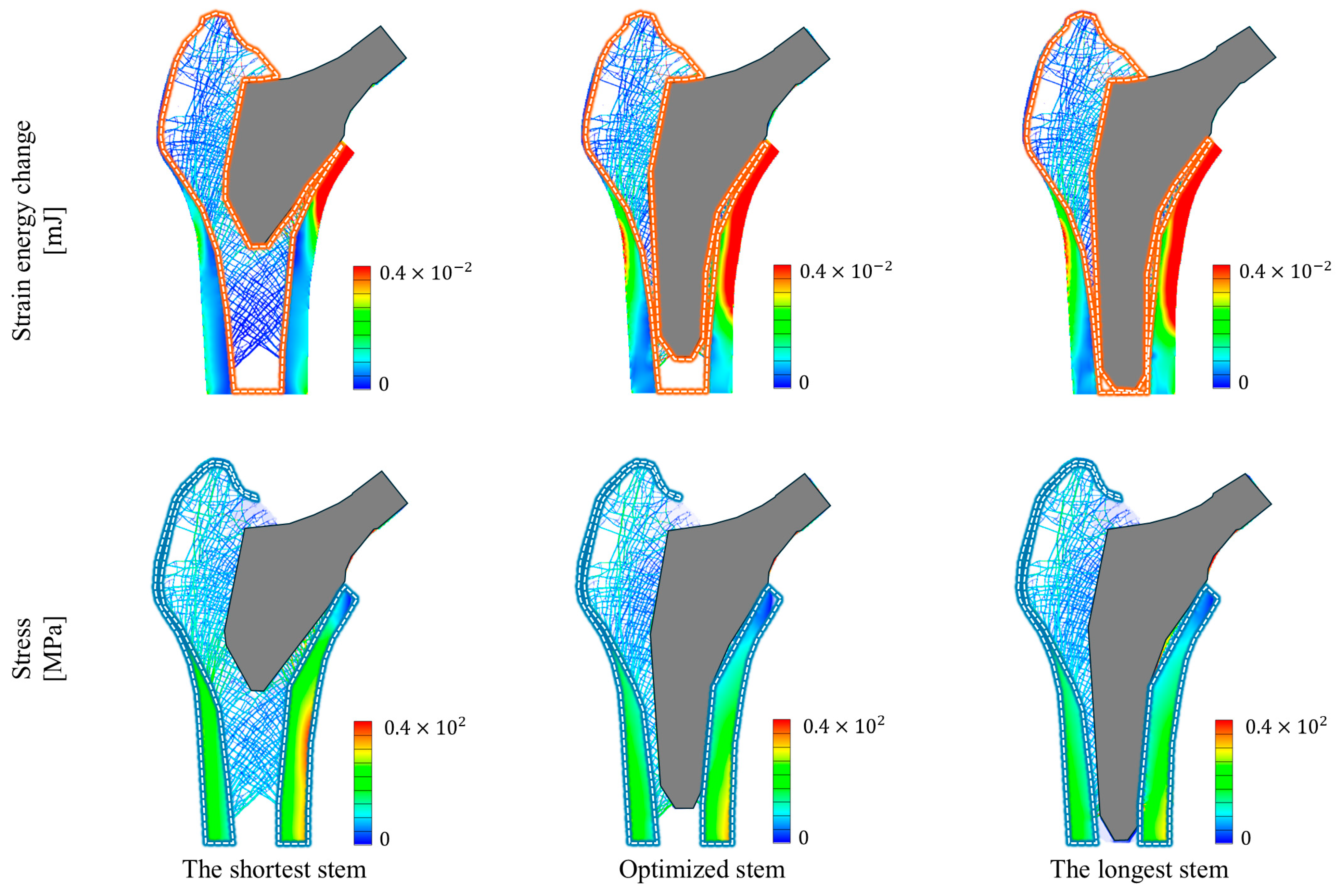
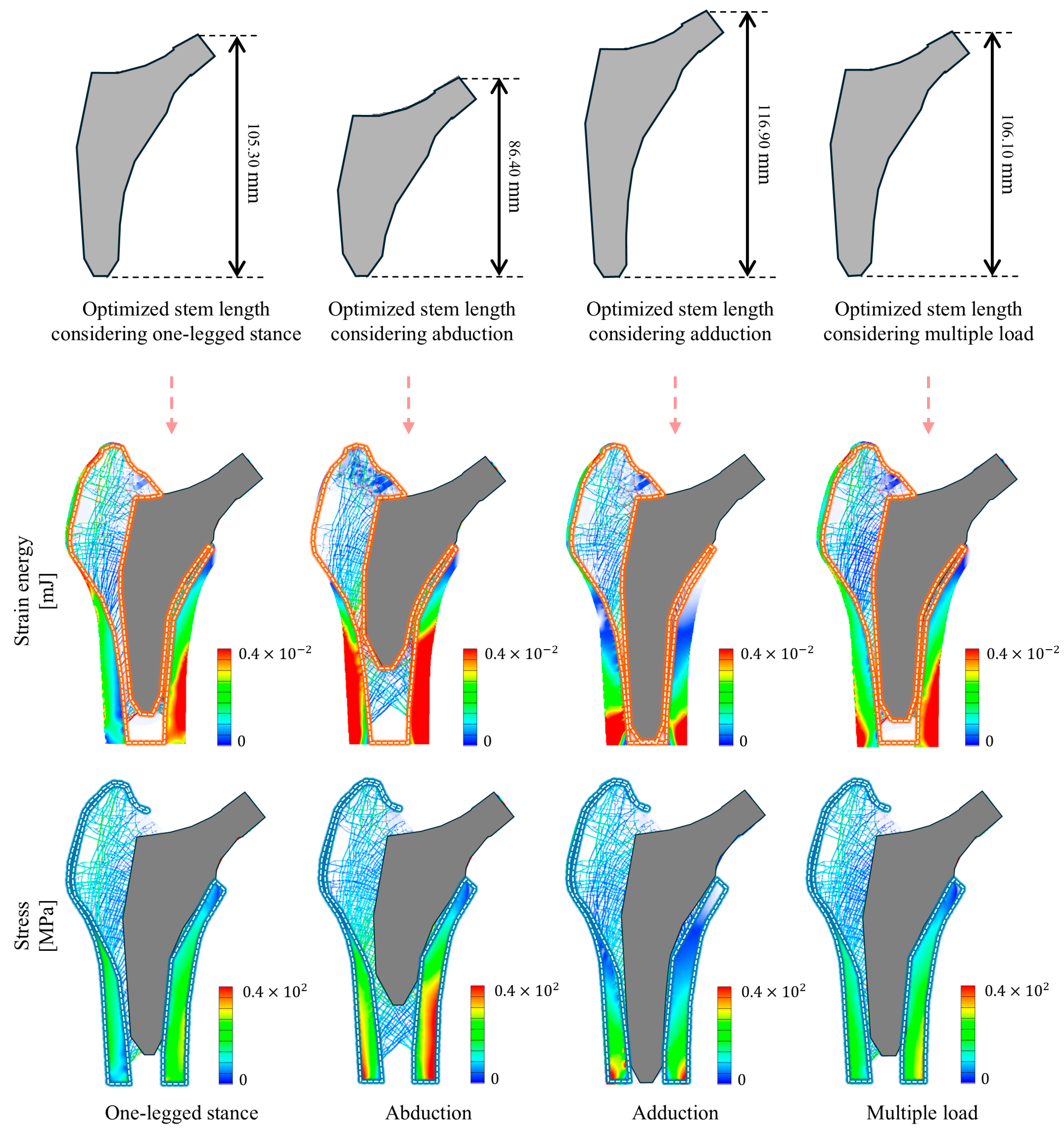
3. Results
4. Discussion
5. Conclusions
Author Contributions
Funding
Institutional Review Board Statement
Informed Consent Statement
Data Availability Statement
Conflicts of Interest
References
- Van Houcke, J.; Khanduja, V.; Pattyn, C.; Audenaert, E. The History of Biomechanics in Total Hip Arthroplasty. Indian J. Orthop. 2017, 51, 359–367. [Google Scholar] [CrossRef] [PubMed]
- Sculco, P.K.; Pagnano, M.W. Perioperative Solutions for Rapid Recovery Joint Arthroplasty: Get Ahead and Stay Ahead. J. Arthroplast. 2015, 30, 518–520. [Google Scholar] [CrossRef] [PubMed]
- Ghalme, S.G.; Mankar, A.; Bhalerao, Y. Biomaterials in Hip Joint Replacement. Int. J. Mater. Sci. Eng. 2016, 4, 113–125. [Google Scholar] [CrossRef]
- Colic, K.; Sedmak, A. The Current Approach to Research and Design of the Artificial Hip Prosthesis: A Review. Rheumatol. Orthop. Med. 2016, 1, 1–7. [Google Scholar] [CrossRef]
- Shan, L.; Shan, B.; Graham, D.; Saxena, A. Total Hip Replacement: A Systematic Review and Meta-Analysis on Mid-Term Quality of Life. Osteoarthr. Cartil. 2014, 22, 389–406. [Google Scholar] [CrossRef]
- Mealy, A.; Sorensen, J. Effects of an Aging Population on Hospital Costs Related to Elective Hip Replacements. Public Health 2020, 180, 10–16. [Google Scholar] [CrossRef]
- De Santis, R.; Gloria, A.; Ambrosio, L. Composite Materials for Hip Joint Prostheses. In Biomedical Composites, 2nd ed.; Elsevier: Amsterdam, The Netherlands, 2017; pp. 237–259. [Google Scholar] [CrossRef]
- Shahzamanian, M.M.; Banerjee, R.; Dahotre, N.B.; Srinivasa, A.R.; Reddy, J.N. Analysis of Stress Shielding Reduction in Bone Fracture Fixation Implant Using Functionally Graded Materials. Compos. Struct. 2023, 321, 117262. [Google Scholar] [CrossRef]
- Lindahl, H.; Malchau, H.; Herberts, P.; Garellick, G. Periprosthetic Femoral Fractures: Classification and Demographics of 1049 Periprosthetic Femoral Fractures from the Swedish National Hip Arthroplasty Register. J. Arthroplast. 2005, 20, 857–865. [Google Scholar] [CrossRef]
- Klasan, A.; Bäumlein, M.; Dworschak, P.; Bliemel, C.; Neri, T.; Schofer, M.D.; Heyse, T.J. Short Stems Have Lower Load at Failure than Double-Wedged Stems in a Cadaveric Cementless Fracture Model. Bone Jt. Res. 2019, 8, 489–494. [Google Scholar] [CrossRef]
- Moscol, I.; Solórzano-Requejo, W.; Ojeda, C.; Rodríguez, C. Personalized Hip Replacement: State of the Art and New Tools Proposals. In Proceedings of the 15th International Joint Conference on Biomedical Engineering Systems and Technologies (BIOSTEC 2022), Online, 9–11 February 2022; pp. 46–57. [Google Scholar] [CrossRef]
- Kim, M.G.; Kim, J.S.; Kim, J.J. 2-D Topology Optimization of the Connection Part of the Electric Kickboard in Case of Front Collision. J. Korean Soc. Precis. Eng. 2022, 39, 841–848. [Google Scholar] [CrossRef]
- Akbar, M.; Aldinger, G.; Krahmer, K.; Bruckner, T.; Aldinger, P.R. Custom Stems for Femoral Deformity in Patients Less than 40 Years of Age: 70 Hips Followed for an Average of 14 Years. Acta Orthop. 2009, 80, 420. [Google Scholar] [CrossRef]
- Escobar, S.B.; Bouguecha, A.; Almohallami, A.; Niemeier, H.; Lucas, K.; Stukenborg-Colsman, C.; Nolte, I.; Wefstaedt, P.; Behrens, B.A. The Customized Artificial Hip Cup: Design and Manufacturing of an Innovative Prosthesis. Lect. Notes Appl. Comput. Mech. 2015, 74, 55–68. [Google Scholar] [CrossRef]
- Nam, L.T.B.; Phuong, N.L.; Dat, N.T.; Cuc, N.T.K. Biomechanical Analysis of a Patient-Specific Artificial Hip Joint to Design and Manufacture It by 3D Printing. In Proceedings of the 3rd Annual International Conference on Material, Machines and Methods for Sustainable Development (MMMS2022); Lecture Notes in Mechanical Engineering; Springer: Cham, Swizerland, 2024; pp. 535–545. [Google Scholar] [CrossRef]
- Jun, Y.; Choi, K. Design of Patient-Specific Hip Implants Based on the 3D Geometry of the Human Femur. Adv. Eng. Softw. 2010, 41, 537–547. [Google Scholar] [CrossRef]
- Naghavi, S.A.; Tamaddon, M.; Garcia-Souto, P.; Moazen, M.; Taylor, S.; Hua, J.; Liu, C. A Novel Hybrid Design and Modelling of a Customised Graded Ti-6Al-4V Porous Hip Implant to Reduce Stress-Shielding: An Experimental and Numerical Analysis. Front. Bioeng. Biotechnol. 2023, 11, 1092361. [Google Scholar] [CrossRef] [PubMed]
- Moscol-Albañil, I.; Solórzano-Requejo, W.; Rodriguez, C.; Ojeda, C.; Díaz Lantada, A. Innovative AI-Driven Design of Patient-Specific Short Femoral Stems in Primary Hip Arthroplasty. Mater. Des. 2024, 240, 112868. [Google Scholar] [CrossRef]
- Feyen, H.; Shimmin, A.J. Is the Length of the Femoral Component Important in Primary Total Hip Replacement? Bone Jt. J. 2014, 96B, 442–448. [Google Scholar] [CrossRef]
- Samy, A.M.; El-Tantawy, A. Stem Length in Primary Cementless Total Hip Arthroplasty: Does It Make a Difference in Bone Remodeling? Eur. J. Orthop. Surg. Traumatol. 2019, 29, 1235–1242. [Google Scholar] [CrossRef]
- Noyama, Y.; Miura, T.; Ishimoto, T.; Itaya, T.; Niinomi, M.; Nakano, T. Bone Loss and Reduced Bone Quality of the Human Femur after Total Hip Arthroplasty under Stress-Shielding Effects by Titanium-Based Implant. Mater. Trans. 2012, 53, 565–570. [Google Scholar] [CrossRef]
- Reimeringer, M.; Nuño, N. The Influence of Contact Ratio and Its Location on the Primary Stability of Cementless Total Hip Arthroplasty: A Finite Element Analysis. J. Biomech. 2016, 49, 1064–1070. [Google Scholar] [CrossRef]
- Kang, J.; Dong, E.; Li, D.; Dong, S.; Zhang, C.; Wang, L. Anisotropy Characteristics of Microstructures for Bone Substitutes and Porous Implants with Application of Additive Manufacturing in Orthopaedic. Mater. Des. 2020, 191, 108608. [Google Scholar] [CrossRef]
- Sabatini, A.L.; Goswami, T. Hip Implants VII: Finite Element Analysis and Optimization of Cross-Sections. Mater. Des. 2008, 29, 1438–1446. [Google Scholar] [CrossRef]
- Carballido-Gamio, J.; Nicolella, D.P. Computational Anatomy in the Study of Bone Structure. Curr. Osteoporos. Rep. 2013, 11, 237–245. [Google Scholar] [CrossRef] [PubMed]
- Abdelaal, O.; Darwish, S.; El-Hofy, H.; Saito, Y. Patient-Specific Design Process and Evaluation of a Hip Prosthesis Femoral Stem. Int. J. Artif. Organs 2019, 42, 271–290. [Google Scholar] [CrossRef] [PubMed]
- Krug, R.; Burghardt, A.J.; Majumdar, S.; Link, T.M. High-Resolution Imaging Techniques for the Assessment of Osteoporosis. Radiol. Clin. N. Am. 2010, 48, 601. [Google Scholar] [CrossRef]
- Huang, Y.J.; Huang, Y.C.; Wang, S.C.; Ku, M.C. Computed Tomography System for Total Knee Replacement Planning and Comparison with Plain Radiography Measured by an Orthopedic Surgeon. J. Imaging Sci. Technol. 2019, 63, 1. [Google Scholar] [CrossRef]
- Chu, C.; Chen, C.; Liu, L.; Zheng, G. FACTS: Fully Automatic CT Segmentation of a Hip Joint. Ann. Biomed. Eng. 2015, 43, 1247–1259. [Google Scholar] [CrossRef]
- Wiese, T.; Yao, J.; Burns, J.E.; Summers, R.M. Detection of Sclerotic Bone Metastases in the Spine Using Watershed Algorithm and Graph Cut. Proc. SPIE 2012, 8315, 309–316. [Google Scholar] [CrossRef]
- Lamecker, H.; Seebass, M.; Hege, H.-C.; Deuflhard, P.; Lamecker, H.; Seebass, M.; Hege, H.-C.; Deuflhard, P. A 3D Statistical Shape Model of the Pelvic Bone for Segmentation. SPIE 2004, 5370, 1341–1351. [Google Scholar] [CrossRef]
- Ehrhardt, J.; Handels, H.; Malina, T.; Strathmann, B.; Plötz, W.; Pöppl, S.J. Atlas-Based Segmentation of Bone Structures to Support the Virtual Planning of Hip Operations. Int. J. Med. Inform. 2001, 64, 439–447. [Google Scholar] [CrossRef]
- Abdel-Wahab, A.A.; Maligno, A.R.; Silberschmidt, V.V. Micro-Scale Modelling of Bovine Cortical Bone Fracture: Analysis of Crack Propagation and Microstructure Using X-FEM. Comput. Mater. Sci. 2012, 52, 128–135. [Google Scholar] [CrossRef]
- Brown, T.D.; Pedersen, D.R.; Gray, M.L.; Brand, R.A.; Rubin, C.T. Toward an Identification of Mechanical Parameters Initiating Periosteal Remodeling: A Combined Experimental and Analytic Approach. J. Biomech. 1990, 23, 893–905. [Google Scholar] [CrossRef] [PubMed]
- Carter, D.R. Mechanical Loading Histories and Cortical Bone Remodeling. Calcif. Tissue Int. 1984, 36 (Suppl. S1), S19–S24. [Google Scholar] [CrossRef] [PubMed]
- Huiskes, R.; Rulmerman, R.; Van Lenthe, G.H.; Janssen, J.D. Effects of Mechanical Forces on Maintenance and Adaptation of Form in Trabecular Bone. Nature 2000, 405, 704–706. [Google Scholar] [CrossRef]
- Turner, C.H. Three Rules for Bone Adaptation to Mechanical Stimuli. Bone 1998, 23, 399–407. [Google Scholar] [CrossRef]
- Vahdati, A.; Roubi, G.; Ghalichi, F.; Tahani, M. Mechanically Induced Trabecular Bone Remodeling Including Cellular Accommodation Effect: A Computer Simulation. Trans. Can. Soc. Mech. Eng. 2008, 32, 371–381. [Google Scholar] [CrossRef]
- Vahdati, A.; Rouhi, G. A Model for Mechanical Adaptation of Trabecular Bone Incorporating Cellular Accommodation and Effects of Microdamage and Disuse. Mech. Res. Commun. 2009, 36, 284–293. [Google Scholar] [CrossRef]
- Rouhi, G.; Epstein, M.; Sudak, L.; Herzog, W. Modeling Bone Resorption Using Mixture Theory with Chemical Reactions. J. Mech. Mater. Struct. 2007, 2, 1141–1155. [Google Scholar] [CrossRef]
- Haase, K.; Rouhi, G. Prediction of Stress Shielding around an Orthopedic Screw: Using Stress and Strain Energy Density as Mechanical Stimuli. Comput. Biol. Med. 2013, 43, 1748–1757. [Google Scholar] [CrossRef]
- Cowin, S.C. Wolff’s Law of Trabecular Architecture at Remodeling Equilibrium. J. Biomech. Eng. 1986, 108, 83–88. [Google Scholar] [CrossRef]
- Raut, P.; Kawade, D.M.M.; Waghmare, P. Finite Element Analysis of Femur Bone Exploring Different Loading Conditions and Modelling Fracture Scenarios. Int. J. Res. Publ. Rev. 2024, 5, 1697–1702. [Google Scholar] [CrossRef]
- Cheng, X.; Yang, Y.; Zhu, J.; Li, G.; Chen, W.; Wang, J.; Zhang, Q.; Zhang, Y. Finite Element Analysis of Basicervical Femoral Neck Fracture Treated with Proximal Femoral Bionic Nail. J. Orthop. Surg. Res. 2023, 18, 926. [Google Scholar] [CrossRef] [PubMed]
- Chi, W.M.; Lin, C.C.; Ho, Y.J.; Lin, H.C.; Chen, J.H. Using Nonlinear Finite Element Models to Analyse Stress Distribution during Subluxation and Torque Required for Dislocation of Newly Developed Total Hip Structure after Prosthetic Impingement. Med. Biol. Eng. Comput. 2018, 56, 37–47. [Google Scholar] [CrossRef] [PubMed]
- Zhang, B.; Rao, S.; Mekkawy, K.L.; Rahman, R.; Sarfraz, A.; Hollifield, L.; Runge, N.; Oni, J.K. Risk Factors for Pain after Total Hip Arthroplasty: A Systematic Review. Arthroplasty 2023, 5, 19. [Google Scholar] [CrossRef] [PubMed]
- Belwanshi, M.; Jayaswal, P.; Aherwar, A. A Study on Finite Element Analysis Methodologies and Approaches Used for Total Hip Arthroplasty. Mater. Today Proc. 2022, 56, 2596–2604. [Google Scholar] [CrossRef]
- Guo, L.; Ataollah Naghavi, S.; Wang, Z.; Nath Varma, S.; Han, Z.; Yao, Z.; Wang, L.; Wang, L.; Liu, C. On the Design Evolution of Hip Implants: A Review. Mater. Des. 2022, 216, 110552. [Google Scholar] [CrossRef]
- Jang, I.G.; Kim, I.Y. Computational Study of Wolff’s Law with Trabecular Architecture in the Human Proximal Femur Using Topology Optimization. J. Biomech. 2008, 41, 2353–2361. [Google Scholar] [CrossRef]
- Khanuja, H.S.; Vakil, J.J.; Goddard, M.S.; Mont, M.A. Cementless Femoral Fixation in Total Hip Arthroplasty. J. Bone Jt. Surg. Am. 2011, 93, 500–509. [Google Scholar] [CrossRef]
- Kim, J.J.; Nam, J.; Jang, I.G. Computational Study of Estimating 3D Trabecular Bone Microstructure for the Volume of Interest from CT Scan Data. Int. J. Numer. Methods Biomed. Eng. 2018, 34, e2950. [Google Scholar] [CrossRef]
- Beaupré, G.S.; Orr, T.E.; Carter, D.R. An Approach for Time-Dependent Bone Modeling and Remodeling--Theoretical Development. J. Orthop. Res. 1990, 8, 651–661. [Google Scholar] [CrossRef]
- Tsubota, K.I.; Adachi, T.; Tomita, Y. Functional Adaptation of Cancellous Bone in Human Proximal Femur Predicted by Trabecular Surface Remodeling Simulation toward Uniform Stress State. J. Biomech. 2002, 35, 1541–1551. [Google Scholar] [CrossRef]
- Han, S.; Kim, R.S.; Harris, J.D.; Noble, P.C. The Envelope of Active Hip Motion in Different Sporting, Recreational, and Daily-Living Activities: A Systematic Review. Gait Posture 2019, 71, 227–233. [Google Scholar] [CrossRef] [PubMed]
- Noroozi, M.; Mohammadi, H.; Efatinasab, E.; Lashgari, A.; Eslami, M.; Khan, B. Golden Search Optimization Algorithm. IEEE Access 2022, 10, 37515–37532. [Google Scholar] [CrossRef]
- Hildebrand, T.; Rüegsegger, P. Quantification of Bone Microarchitecture with the Structure Model Index. Comput. Methods Biomech. Biomed. Engin. 1997, 1, 15–23. [Google Scholar] [CrossRef]
- Wiik, A.V.; Aqil, A.; Al-Obaidi, B.; Brevadt, M.; Cobb, J.P. The Impact of Reducing the Femoral Stem Length in Total Hip Arthroplasty during Gait. Arch. Orthop. Trauma Surg. 2021, 141, 1993–2000. [Google Scholar] [CrossRef] [PubMed]
- Davidson, D.; Pike, J.; Garbuz, D.; Duncan, C.P.; Masri, B.A. Intraoperative Periprosthetic Fractures during Total Hip Arthroplasty: Evaluation and Management. J. Bone Jt. Surg. 2008, 90, 2000–2012. [Google Scholar] [CrossRef]
- Li, J.; Gong, H. Fatigue Behavior of Cortical Bone: A Review. Acta Mech. Sin. 2021, 37, 516–526. [Google Scholar] [CrossRef]
- Reimeringer, M.; Nuño, N.; Desmarais-Trépanier, C.; Lavigne, M.; Vendittoli, P.A. The Influence of Uncemented Femoral Stem Length and Design on Its Primary Stability: A Finite Element Analysis. Comput. Methods Biomech. Biomed. Eng. 2013, 16, 1221–1231. [Google Scholar] [CrossRef]
- Savio, D.; Bagno, A. When the Total Hip Replacement Fails: A Review on the Stress-Shielding Effect. Processes 2022, 10, 612. [Google Scholar] [CrossRef]
- Turner, A.W.L.; Gillies, R.M.; Sekel, R.; Morris, P.; Bruce, W.; Walsh, W.R. Computational Bone Remodelling Simulations and Comparisons with DEXA Results. J. Orthop. Res. 2005, 23, 705–712. [Google Scholar] [CrossRef]
- Park, C.-W.; Lim, S.-J.; Park, Y.-S. Modular Stems: Advantages and Current Role in Primary Total Hip Arthroplasty. Hip Pelvis 2018, 30, 147–155. [Google Scholar] [CrossRef]
- Mirza, S.B.; Dunlop, D.G.; Panesar, S.S.; Naqvi, S.G.; Gangoo, S.; Salih, S. Basic Science Considerations in Primary Total Hip Replacement Arthroplasty. Open Orthop. J. 2010, 4, 169. [Google Scholar] [CrossRef] [PubMed]

| Material | Young’s Modulus (GPa) | Poisson’s Ratio |
|---|---|---|
| Cortical Bone | 22.50 | 0.30 |
| Cancellous Bone * | 15.00 | 0.30 |
| Titanium Alloy | 114.0 | 0.32 |
| Index | Type of Hip Stem | ||
|---|---|---|---|
| The Shortest Stem | Optimized Stem | The Longest Stem | |
| Optimized stem length [mm] | 68.750 | 106.10 | 117.35 |
| Strain energy change rate [%] | 9.4028 (−65.3%) | 27.079 | 32.127 (+18.6%) |
| Maximum stress [MPa] | 115.84 (+14.5%) | 101.17 | 108.28 (+7.03%) |
| Index | Type of Loading Condition | |||
|---|---|---|---|---|
| One-Legged Stance | Abduction | Adduction | Multiple Load | |
| Optimized stem length [mm] | 105.30 | 86.400 | 116.90 | 106.10 |
| Strain energy change rate [%] | 29.034 | 12.693 | 24.168 | 27.079 |
| Maximum stress [MPa] | 63.461 | 128.34 | 181.75 | 101.17 |
Disclaimer/Publisher’s Note: The statements, opinions and data contained in all publications are solely those of the individual author(s) and contributor(s) and not of MDPI and/or the editor(s). MDPI and/or the editor(s) disclaim responsibility for any injury to people or property resulting from any ideas, methods, instructions or products referred to in the content. |
© 2024 by the authors. Licensee MDPI, Basel, Switzerland. This article is an open access article distributed under the terms and conditions of the Creative Commons Attribution (CC BY) license (https://creativecommons.org/licenses/by/4.0/).
Share and Cite
Kim, S.M.; Choi, J.W.; Kim, J.J. Personalized Stem Length Optimization in Hip Replacement: A Microscopic Perspective on Bone—Implant Interaction. Bioengineering 2024, 11, 1074. https://doi.org/10.3390/bioengineering11111074
Kim SM, Choi JW, Kim JJ. Personalized Stem Length Optimization in Hip Replacement: A Microscopic Perspective on Bone—Implant Interaction. Bioengineering. 2024; 11(11):1074. https://doi.org/10.3390/bioengineering11111074
Chicago/Turabian StyleKim, Su Min, Jun Won Choi, and Jung Jin Kim. 2024. "Personalized Stem Length Optimization in Hip Replacement: A Microscopic Perspective on Bone—Implant Interaction" Bioengineering 11, no. 11: 1074. https://doi.org/10.3390/bioengineering11111074
APA StyleKim, S. M., Choi, J. W., & Kim, J. J. (2024). Personalized Stem Length Optimization in Hip Replacement: A Microscopic Perspective on Bone—Implant Interaction. Bioengineering, 11(11), 1074. https://doi.org/10.3390/bioengineering11111074