Abstract
During the vascular surgical reconstruction of aorto-iliac occlusive/aneurysmal disease, bifurcated grafts are used where vascular surgeons intra-operatively select the size and the relative lengths of the parent and daughter portions of the graft. Currently, clinical practice regarding the selection of the most favorable geometric configuration of the graft is an understudied research subject: decisions are solely based on the clinical experience of the operating surgeon. This manuscript aims to evaluate the hemodynamic performance of various diameters, D, of bifurcated aortic grafts and relate those with proximal/distal part length ratios (the angle φ between the limbs is used as a surrogate marker of the main body-to-limb length ratio) in order to provide insights regarding the effects of different geometries on the hemodynamic environment. To this end, a computationally intensive set of simulations is conducted, and the resulting data are analyzed with modern statistical regression tools. A negative curvilinear relationship of TAWSS with both φ and D is recorded. It is shown that the angle between limbs is a more important predictor for the variability of TAWSS, while the graft’s diameter is an important determinant for the variability of OSI. Large percentages of the total graft area with TAWSS < 0.4 Pa, which correspond to thrombogenic stimulating environments, are only observed for large values of φ and D > 20 mm. This variable ranges from 10% (for the smallest values of φ and D) to 55% (for the largest φ and D values). Our findings suggest that grafts with the smallest possible angle between the limbs (i.e., smallest parent-to-daughter length ratio) present the most favorable hemodynamic performance, yielding the smallest percentage of total graft area under thrombogenic simulating environments. Similarly, grafts with the smallest acceptable diameter should be preferred for the same reason. Especially, grafts with diameters greater than 20 mm should be avoided, given the abrupt increase in estimated thrombogenic areas.
1. Introduction
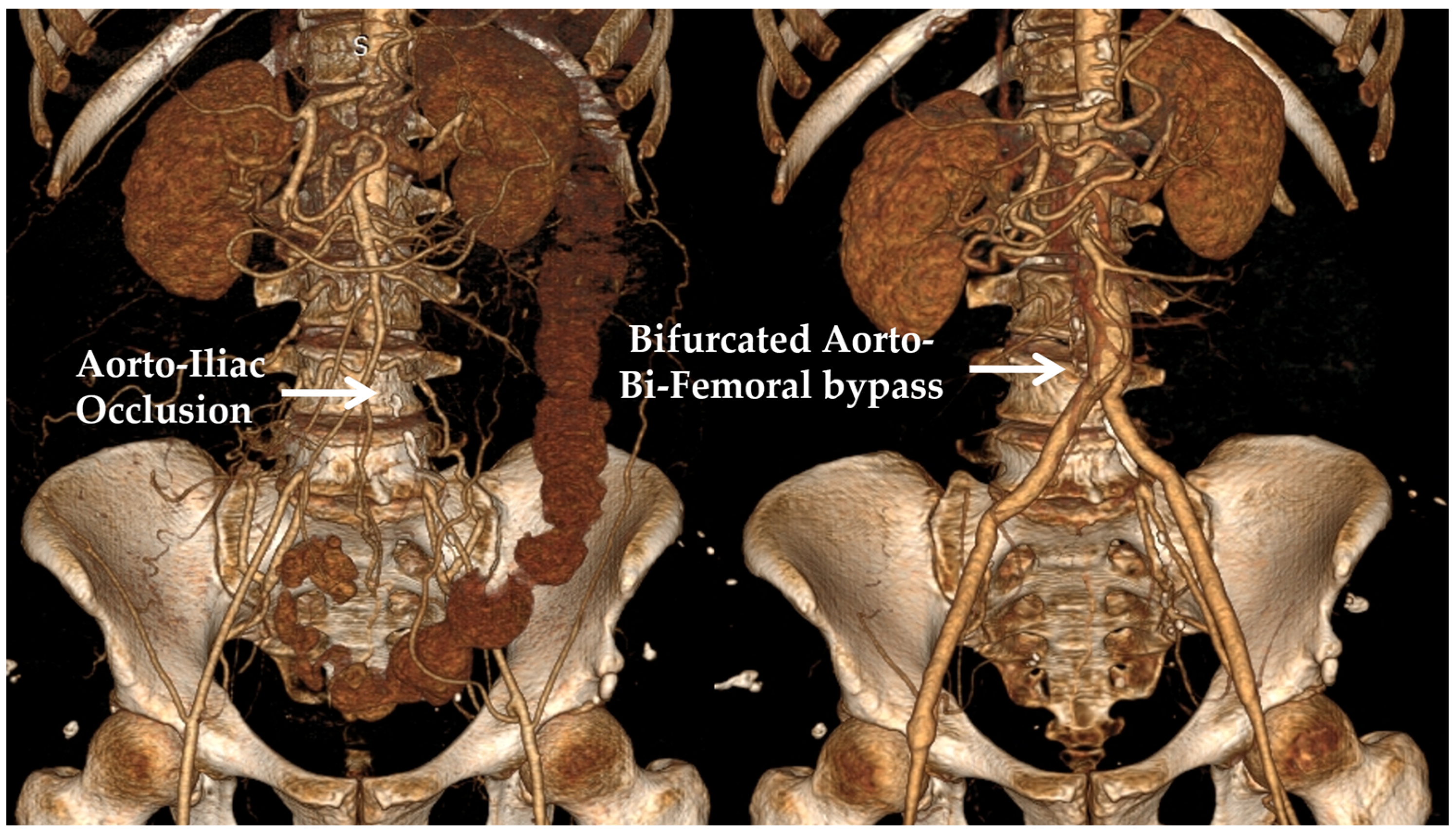
Traditionally, vascular surgery has mainly employed surgical procedures where a conduit is used in order to either bypass an occluded arterial segment (atherosclerotic occlusive disease) or replace a diseased and degenerated part of an artery (aneurysmal disease). In one of the most common clinical scenarios, the occlusive or aneurysmal disease affects the aorto-iliac part of the vasculature; in this case, an aorto-bi-iliac or aorto-bi-femoral bifurcated graft is usually employed. Abdominal aortic aneurysms are found in 2–3% of the population older than 65 years of age in the developed world, which, should they escape diagnosis and then enlarge and eventually rupture, can cause an immediate threat to the patient’s life. Aorto-iliac obstructive disease is a distinct pathology that can significantly limit the walking ability of patients, affecting their quality of life and, in extreme cases, posing a threat to limb viability [1]. Considering that the vertical distance between the infra-renal aorta used as the inflow site and the iliac or femoral arteries (target vessels) is patient-specific, a number of options exist regarding the relative length of the main body and the limbs of the graft. Bifurcated aortic grafts are usually manufactured as 20 cm long main tubes that split into two 30 cm long distal tubes; hence, surgeons may intra-operatively shape the graft according to the specific anatomic requirements of each patient. Moreover, aortic grafts are available in a variety of diameter combinations, where the parent tube usually has twice the diameter of the daughter tubes. Typical diameters range from 12 mm (proximal part)/6 mm (distal limbs) to 24 mm/12 mm in increments of 2 mm. Currently, there is no guidance regarding the configuration that should be selected when such a bypass is constructed [2,3]. In most cases, a relatively short main body with two relatively long distal limbs, or a relatively long main body with two relatively short distal limbs, is selected for every patient, based on each surgeon’s preference. An example of a bifurcated aorto-be-femoral bypass of a patient with aorto-iliac obstruction is presented in Figure 1.
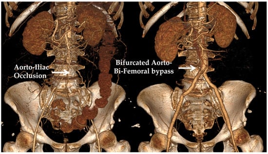
Figure 1.
(Left panel): A 3D reconstruction of the pre-operative CT angiography of a patient with aorto-iliac obstruction. (Right panel): The post-operative CT angiography is shown, displaying an aorto-bi-femoral bypass used for treatment.
On the contrary, the specific anatomy of each patient may dictate the need for a relatively narrow or a relatively wide graft to be used, but a variety of options still exist that are compatible with these requirements. For example, for a 20 mm wide infrarenal aorta, a 16 mm, 18 mm, 20 mm, or 22 mm graft would be considered acceptable. The choice among these options is based on each surgeon’s personal experience and preference, in order to perform a technically sound proximal anastomosis between the native vessel and the synthetic graft. A clinical aspect that has been largely unexplored in the literature is the hemodynamic effects of blood on all alternative graft configurations. Many studies have used computational modeling to evaluate the hemodynamic performance of aortic endografts used during the endovascular repair of AAAs. These examine a variety of outcomes, such as displacement forces, wall stresses, the comparative effects of the “ballerina” versus the standard graft configuration, etc. Although research on the effects of different main body-to-limb length ratios in endovascular stent-grafts has been performed, this has not determined a definite conclusion on the configurations that may be beneficial [4,5]. Moreover, analyses that have evaluated the hemodynamic effects of the relative lengths of the proximal part and distal limbs on surgical grafts are very scarce, with only a recent publication suggesting a possible benefit of a longer main body configuration due to a reduced overall hydraulic resistance [6]. Similarly, although the effect of the inlet diameter has been scarcely examined for endovascular stent-grafts, with the beneficial effect of lower profile devices having been suggested [7], we could not retrieve any studies that have examined the effect of different diameter values on the hemodynamic performance of surgical grafts [8]. To the best knowledge of the authors, there have been no investigations that have associated the hemodynamic effect of alternative graft diameters with the relative length of the proximal/distal parts of the graft.
This manuscript aims to examine the hemodynamic effects of the alternative diameter values of a bifurcated aortic graft and relate them with various proximal/distal part length ratios, in order to provide insights regarding the hemodynamic performance of different geometric configurations and, consequently, to guide clinical practice. A high main body-to-limb length ratio is accompanied by an increased angle between the limbs of the graft, which could be hypothesized to result in flow disturbances and in an unfavorable hemodynamic profile. Additionally, the effect of the inlet diameter of the graft is examined to identify hemodynamically advantageous conditions. For this purpose, a computationally intensive set of simulations is conducted, and the numerical outputs are analyzed with modern statistical regression tools. The paper is organized as follows: Section 2 presents the mathematical framework adopted for the numerical simulations of non-Newtonian fluid flow. Furthermore, it depicts the statistical methodology, which underlies the analysis of the data produced by the simulations. The outcomes are displayed in Section 3 and discussed in Section 4; finally, Section 5 contains the conclusions.
2. Materials and Methods
2.1. Simulation Setup
Blood is considered an incompressible, non-Newtonian fluid and is simulated by solving the three-dimensional Navier-Stokes (expressed in vectorial form) and continuity equations
respectively, where represent fluid velocity, pressure, and density, respectively. For the needs of this study, the shear-rate-dependent viscosity of blood, depends on the deviatoric stress, and the shear rate, as follows
Various non-Newtonian models have been proposed in the literature for mimicking blood behavior, all aiming to capture deviations from the corresponding Newtonian one. These models include the Carreau-Yasuda [9,10,11,12], Herschel-Bulkley [13,14], and Casson [10,15] models, amongst others. An investigation of the literature reveals that different rheological models are interchangeably used in numerical simulations, with uncertain implications for the results obtained. An attempt to group alternative models in homogeneous clusters has been performed [16], suggesting that data generated from models in different clusters are significantly different. In this work, the Carreau-Yasuda (CY) model is adopted, which is formulated as
with and [11]. Since blood flow is assumed to be incompressible, its density is considered constant and equal to [17].
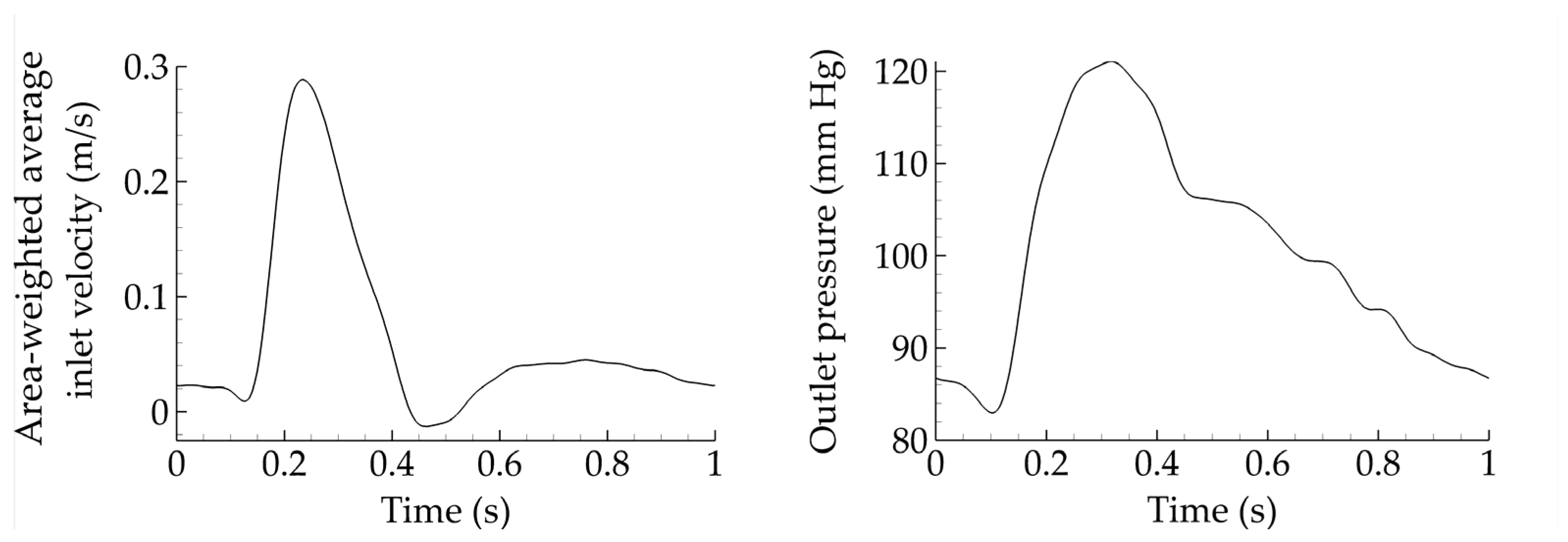
A commercial finite volume solver is utilized (Fluent 17.2, ANSYS Inc., Canonsburg, PA, USA), with a constant convergence criterion set equal to 10−5 and a time step of 0.005 s. Appropriate boundary conditions are considered. Specifically, velocity inlet and pressure outlet waveforms are taken from Olufsen et al. [18] and depicted in Figure 2. Such waveforms constitute a standard set of boundary conditions in blood flow simulations. Finally, the flow split between limbs is assumed to be equal. It should be noted that the assumption of constant inlet velocity and outlet pressure allows us to safely compare all cases and draw meaningful conclusions. However, such constant boundary conditions may not be very realistic, and differences may emerge if one adapts them in terms of the geometrical characteristics of the grafts. In that sense, this assumption should be considered a limitation of the present study.
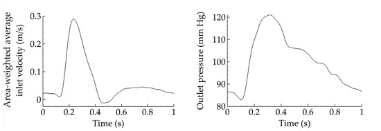
Figure 2.
Area-weighted average inlet velocity and outlet pressure for all cases considered.
In all cases, the flow remains laminar and the inlet velocity profile, is assigned by utilizing a user-defined function (UDF) based on the Womersley method [19], with a corresponding Womersley parameter α (Table 1), given by

Table 1.
Mean and peak Reynolds number as well as Womersley parameter for varying levels of the inlet diameter.
The velocity profile is thus described in terms of the angular frequency, ω, and Bessel function, J0.
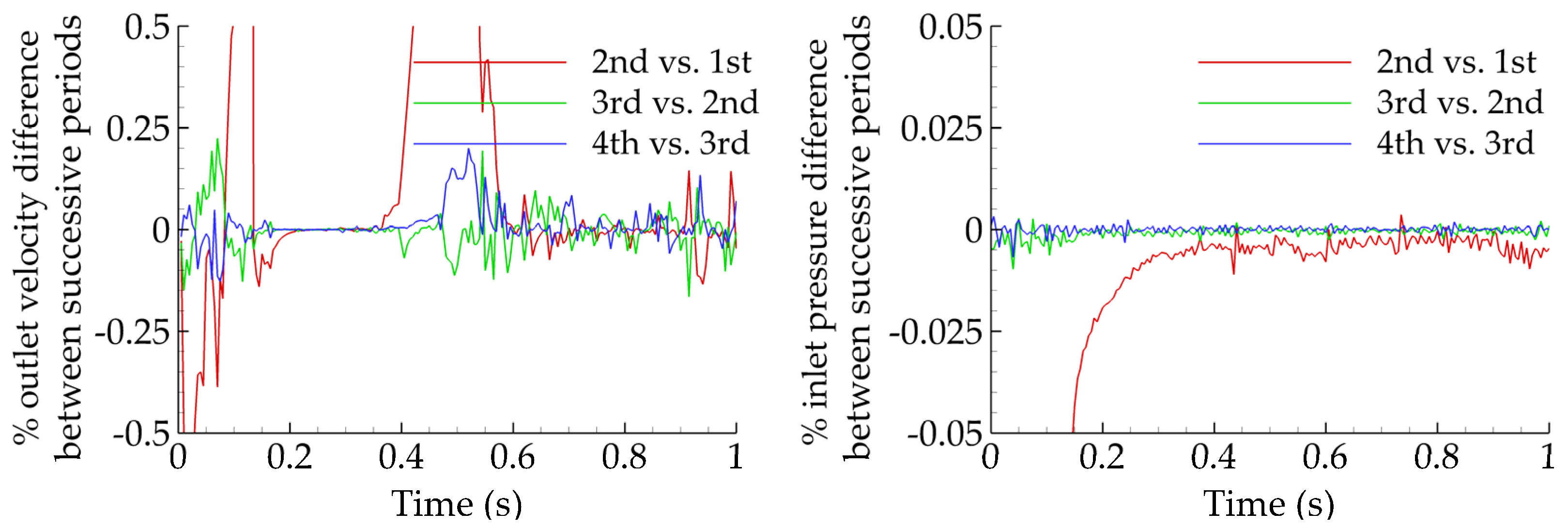
A constant cardiac cycle of one second is assumed for all simulations and four cycles are considered before the results are collected, to ensure that all transient effects are washed out. This can be observed in Figure 3, where the percentage errors for the outlet velocity magnitude and inlet pressure are plotted for successive periods. The error between periods three and four (blue solid) is always less than 0.25%, making period five appropriate for data collection.
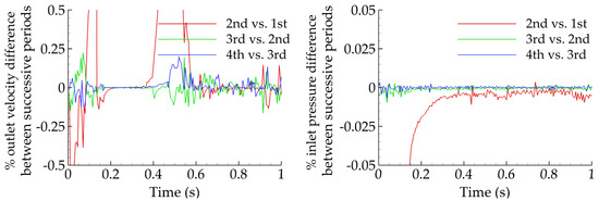
Figure 3.
Percentage difference of outlet velocity magnitude (left) and inlet pressure (right) for various successive periods. The difference does not exceed a few tenths of a percent between periods three and four.
The analyses that follow are based on thirty-five idealized geometries. In all cases, the distance between renal and femoral arteries is fixed (L = 25 cm) and the same holds for the distance between femoral arteries and the midline (l = 7 cm; Figure 4). These values were derived from the evaluation of 10 patient-specific cases treated in our institution. Following the geometric characteristics of commercial grafts, the ratio of the inlet-to-outlet diameter is kept constant and equal to two. Seven diameter configurations D/d (mm) = (12/6, 14/7, 16/8, 18/9, 20/10, 22/11, 24/12) and five limb angles φ (°) = (35, 40, 47, 56, 70) are examined. Assuming a value for the length of the parent vessel y per limb angle, these five cases are characterized by y (cm) = (3, 6, 9, 12, 15), respectively. It is then possible to evaluate the corresponding length of the daughter vessel, x, as using trivial geometric calculations it can be shown that The five resulting triplets {φ(°)/y(cm)/x(cm)} simulated for each one of the seven diameter configurations are the following: 35/3/23.3, 40/6/20.2, 47/9/17.5, 56/12/14.8, and 70/15/12.2. Assuming rigid walls, all CAD models are built using SolidWorks (Dassault Systèmes, Velizy-Villacoublay, France). Figure 4 presents all examined angles with the corresponding lengths of parent and daughter vessels and all available inlet diameters, which produce the thirty-five simulation cases in total.

Figure 4.
All assumed limb angles and inlet diameters of the idealized geometry. For visualization purposes, only half of the limb angle is shown.
Vascular flows can be analyzed in terms of near-wall hemodynamic parameters over the entire cardiac cycle, T, such as the wall shear stress (WSS) and its most commonly used metrics, the time average wall shear stress (TAWSS, Pa), the oscillatory shear index (OSI), and the relative residence time (RRT, Pa−1). Let WSS represent the WSS vector, defined as the dot product of the outward unit normal vector on a surface with the stress tensor. TAWSS is then calculated as the following integral [20]
TAWSS quantifies the tangential force on the vessel wall due to blood flow as the average magnitude of the shear stress, but does not provide any information on the varying frequency of the WSS direction. In order to describe the oscillatory nature of flows, the non-dimensional OSI introduced in [20] is formulated as follows
with Flows characterized by no cyclic variation of WSSB, such as uniaxial flows, correspond to while flows with no preferred direction, where the time average of the instantaneous WSS vanishes, yield OSI = 0.5.
Himburg et al. [21] introduced RRT in terms of the two previous hemodynamic markers as
RRT identifies regions of high-particle residence time close to the wall domain. The three aforementioned metrics have been associated with various diseased states, such as thrombogenic stimulating environments for TAWSS < 0.4 Pa, OSI > 0.3, and RRT > 10 Pa−1 [20,22,23,24,25].
2.2. Mesh Generation and Convergence
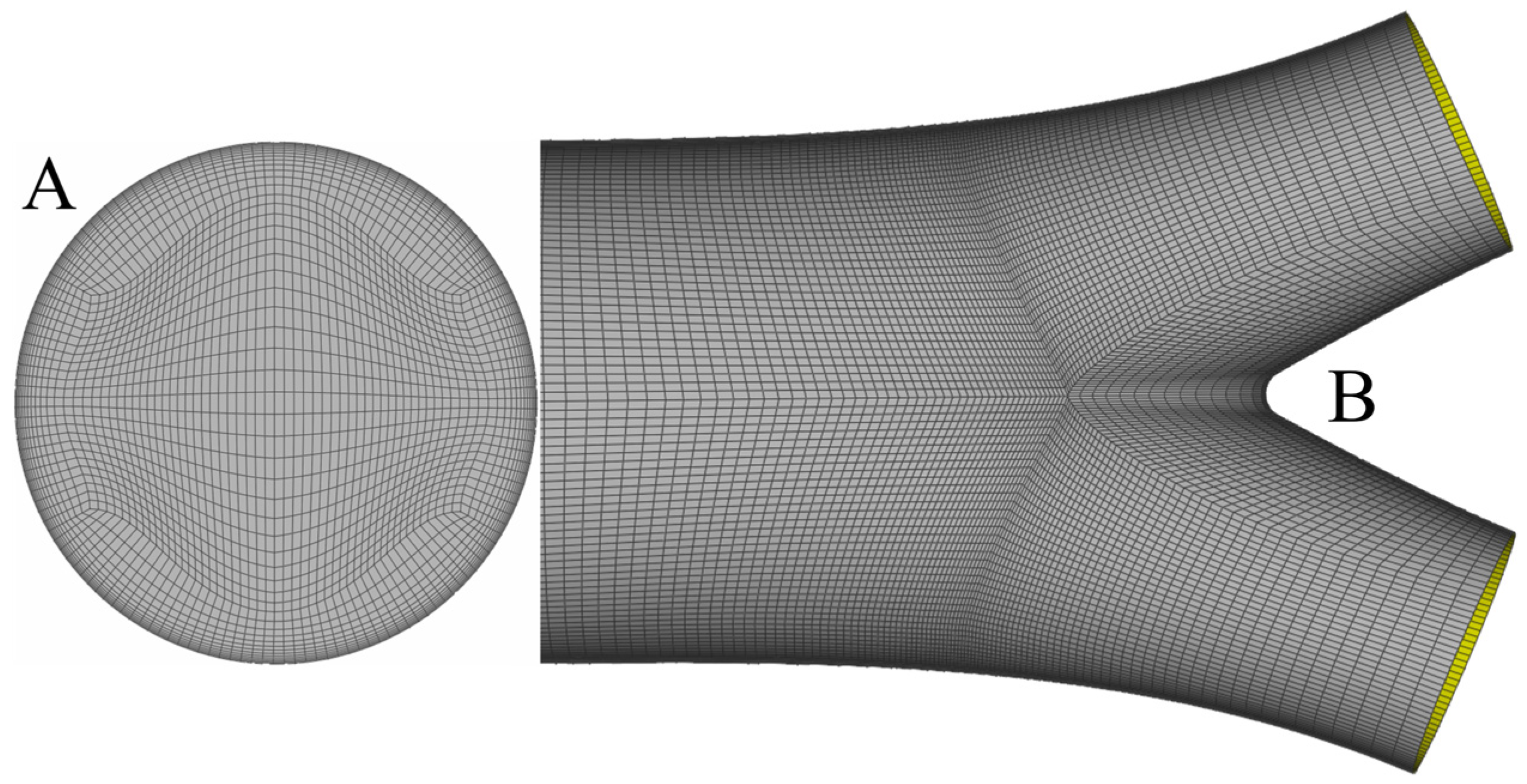
In all cases, the solid model is produced by SolidWorks and meshed with ANSA (BETA CAE Systems S.A., Yokohama, Japan) using a pure hexahedral mesh. Hexahedral meshes require a fewer number of elements compared to tetrahedral or prismatic ones for a fixed level of accuracy, as shown in [26]. A sufficient number of elements is clustered close to the wall in order to capture high-velocity gradients. Figure 5 presents the inlet mesh (A) and part of the surface mesh (B) close to the bifurcation area.
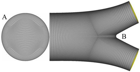
Figure 5.
Inlet mesh with the corresponding O-Grid for the construction of the boundary layer (A) and the surface mesh close to the bifurcation area (B). One observes that mesh density increases while moving towards the bifurcation, to capture non-trivial flow patterns.
To assess mesh convergence, four meshes are constructed with a successive increase of elements by a factor approximately equal to two. Since it is not possible to validate convergence for all thirty-five simulations, one is selected as the benchmark. The chosen case corresponds to the triplet {φ(°)/D(mm)/d(mm)} = {70/12/6}, which is characterized by a significant boundary layer due to the smallest available diameter and non-trivial flow effects as a consequence of the largest available limb angle. An error threshold of 1% in TAWSS, OSI, and RRT is adopted for mesh convergence. The results are summarized in Table 2 and Table 3; one can clearly observe that the required threshold is achieved with the so-called fine mesh.

Table 2.
Details of the four meshes examined for the triplet {φ(°)/D(mm)/d(mm)} = {70/12/6}. The table presents the total number of elements, as well as the number of boundary layer (BL) levels and the minimum element size on BL.

Table 3.
Area-weighted average results and percentage errors for TAWSS, OSI, and RRT. All errors are calculated with respect to the extra fine mesh.
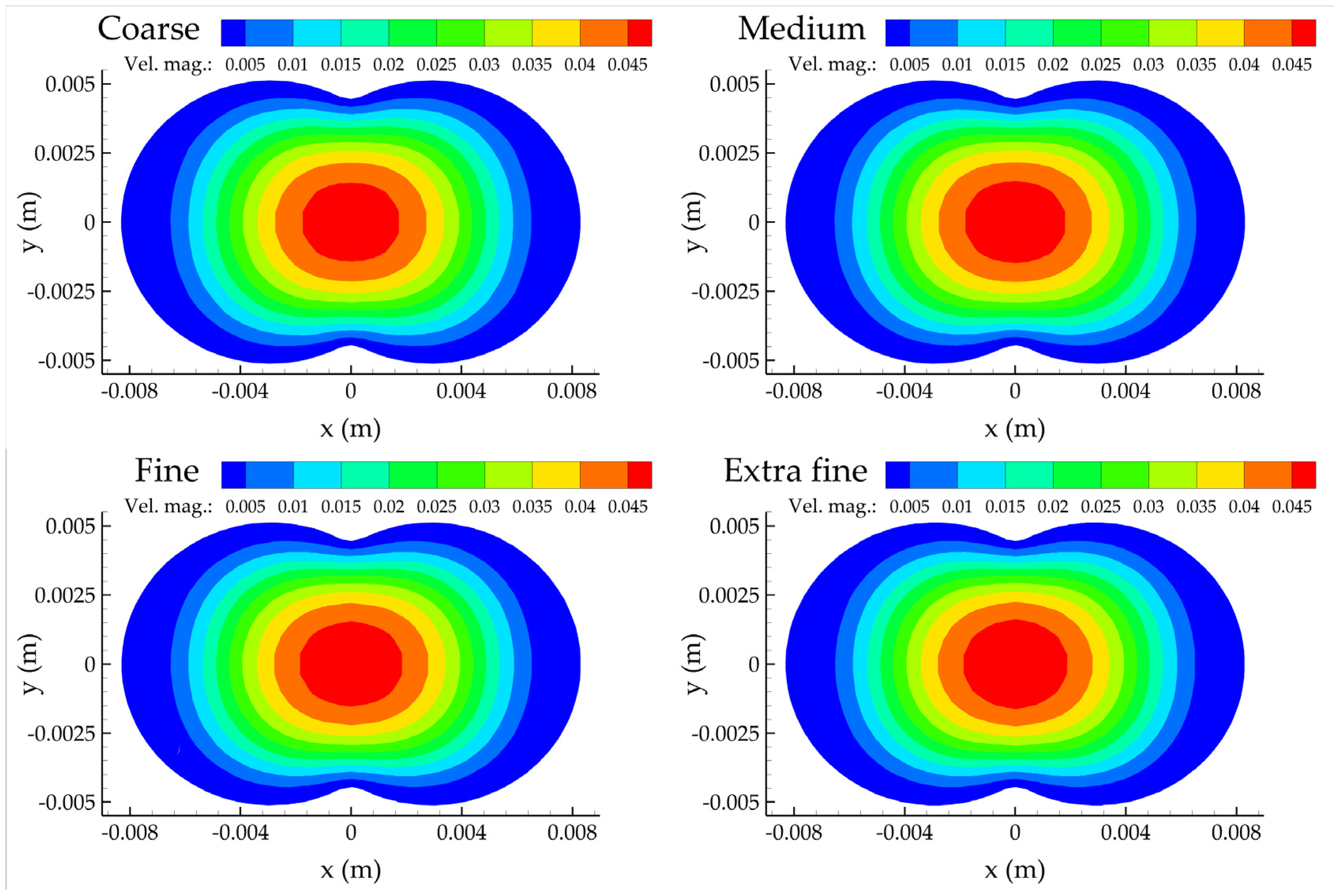
Figure 6 presents the contours of the velocity magnitude for all meshes considered at the z = 0 plane, defined as the normal to the inlet plane where the three centerlines meet. No apparent differences can be observed; they all share the same qualitative features. The velocity field is characterized by small values close to the wall due to the no-slip boundary condition, and with larger values at the center of the computational domain.
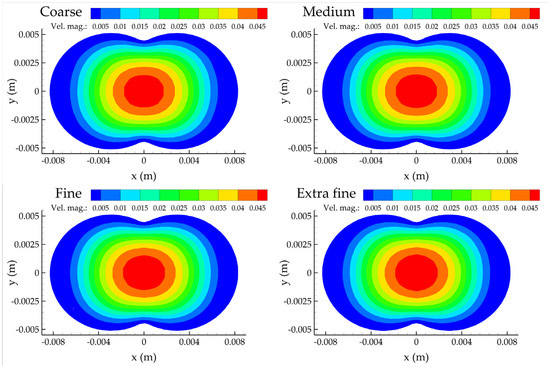
Figure 6.
Contour plots of the velocity magnitude at the z = 0 plane for the four mesh refinements.
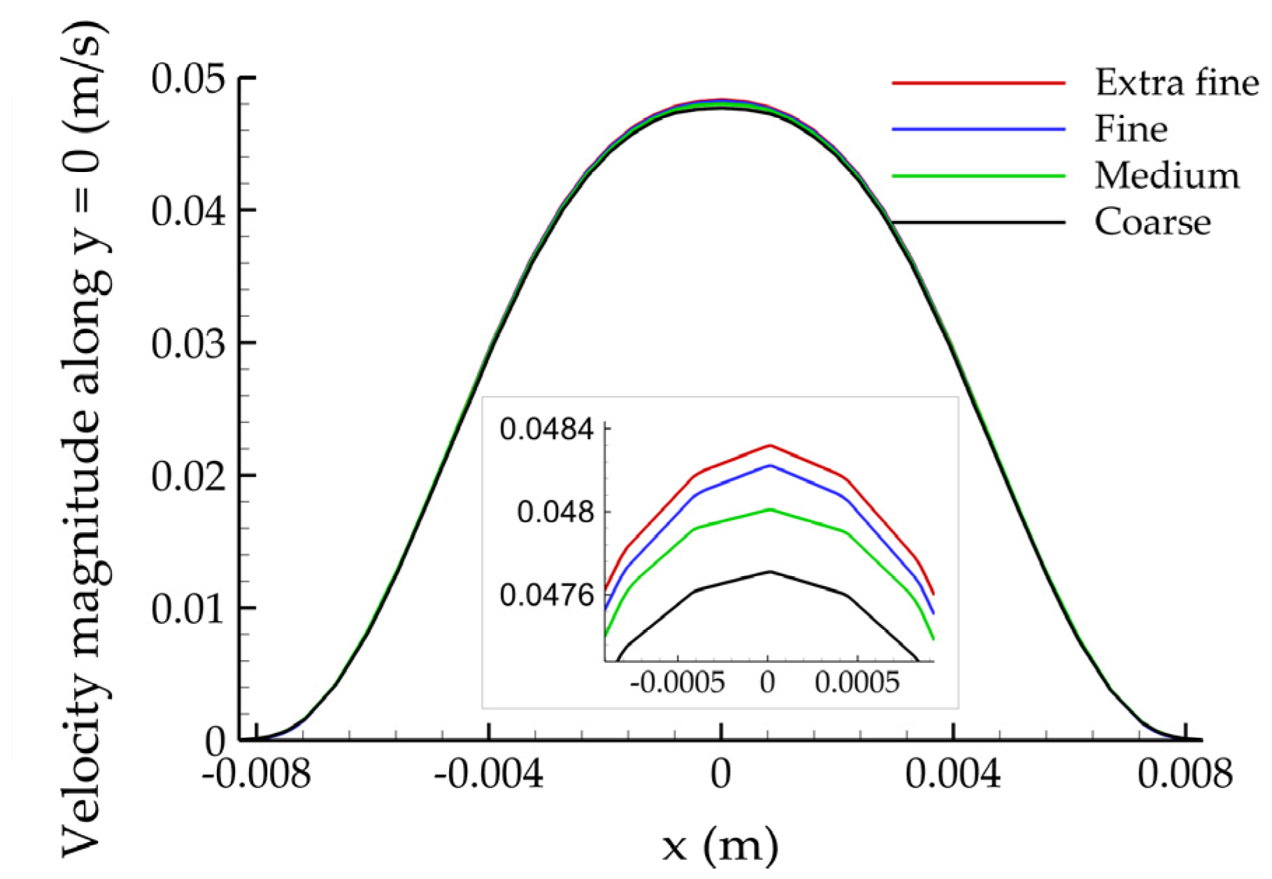
Figure 7 depicts the velocity magnitude along the y = 0 line of the z = 0 plane. Observing the (magnified) close-ups maxima, it is clear that the solution converges to a constant value with increasing mesh density.
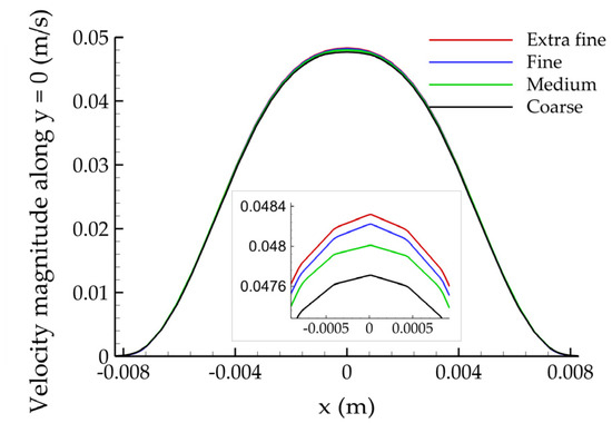
Figure 7.
Plot of the velocity magnitude along the y = 0 line of the z = 0 plane for the four mesh refinements.
2.3. Statistical Analysis
The associations of hemodynamic variables with D and φ are quantified with second order regressions that allow for curvilinear and interaction effects. The general linear (in parameters) specification predicts each response as a curvilinear surface that depends on the levels of D and φ, and uses six unknown parameters, namely Specifically, parsimonious variants of the following predictive model
are evaluated, using each hemodynamic variable (e.g., averaged TAWSS, OSI, and RRT for the whole graft) as the response divisions with 1000 in (8) ease the interpretability of the estimated coefficients without essentially affecting the results. The specification shown above is coupled with backward elimination, a model-building procedure based on the corrected-Akaike information criterion (AICc). AICc leads to improved model-building decisions relative to conventional AIC, especially in small samples [27]. Statistical computations utilize the R packages MuMIn [28] and quantreg [29].
The second-order specification (8) is estimated by the widely adopted least absolute deviations (LAD, or median regression) estimator [29], which can be easily modified to lead to quantile-specific predictive models. The latter are useful tools to assess heteroscedastic associations, with varying levels of uncertainty for different levels of predictors. The reported standard errors for coefficient estimates are computed with a computationally intensive bootstrap procedure, which does not rely on distributional assumptions [30]. Preliminary analyses show that the bootstrap leads to significantly different (typically larger) standard error estimates relative to the frequently applied Gaussian-based ones. This finding suggests that the normality assumption is suboptimal for the analyzed data. Finally, the reported goodness-of-fit, GoF, metric is median-regression appropriate: the variability of residuals relative to is quantified with MAD, the median absolute deviation from the median.
3. Results
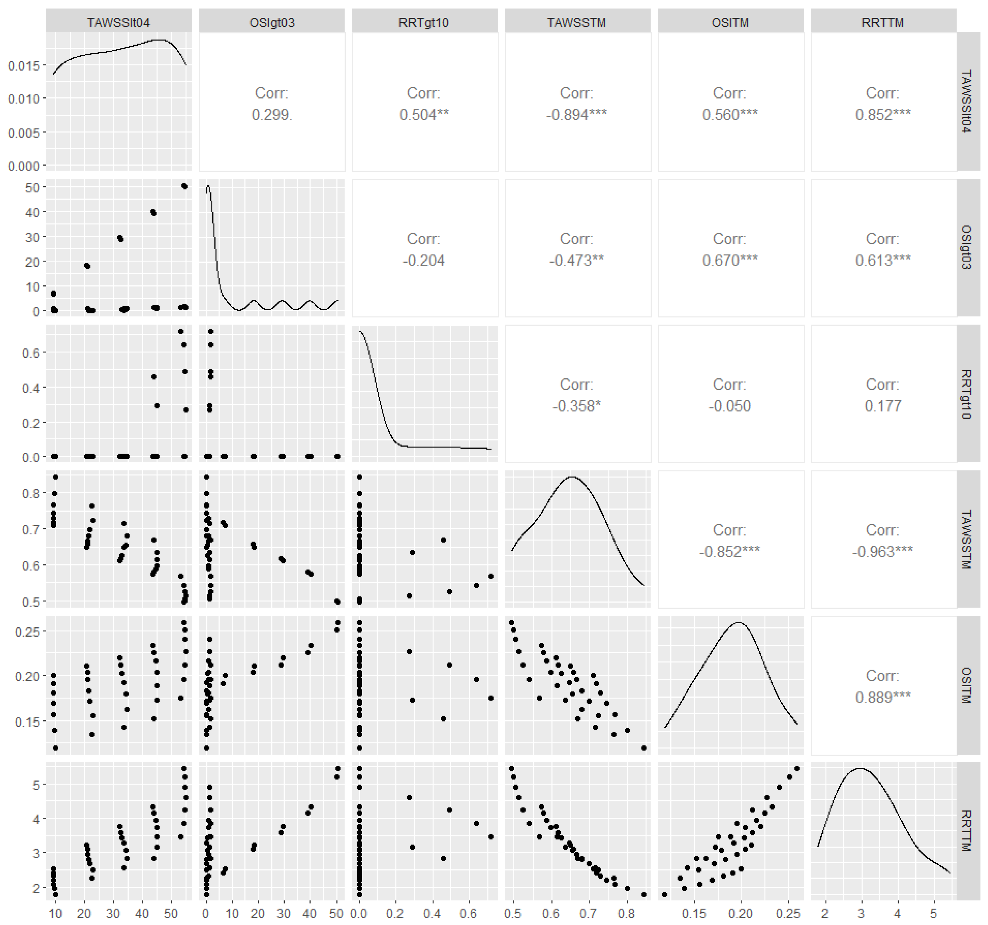
The analyzed data are summaries of the hemodynamic variables, which correspond to alternative combinations of graft diameters (D/d) with limb angles φ. Table 4 and Figure 8 depict outlier-robust 10% trimmed means (TM) for TAWSS, OSI, and RRT for the thirty-five idealized geometries. Pearson’s rho, a measurement of linear association, is also shown in Figure 8. In accordance with previous studies [13], area-weighted averaged TAWSS (TAWSSTM) is strongly, negatively associated with the corresponding values of both averaged RRT (RRTTM) and averaged OSI (OSITM). In fact, the correlation of TAWSSTM with RRTTM is almost perfect, which suggests that analyzing one variable from this pair is sufficient. Thus, the following statistical models use TAWSSTM as the response.

Table 4.
Summary statistics of hemodynamic variables for different combinations of graft diameters (D/d) with limb angles φ; 10% trimmed means of calculated TAWSS (TAWSS TM), OSI (OSI TM), and RRT (RRT TM) are reported, to eliminate the effect of outliers.
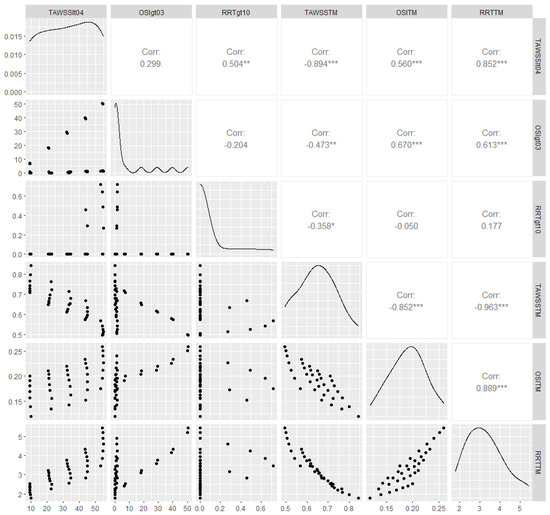
Figure 8.
Scatterplots (lower diagonal), density plots (diagonal), and estimated Pearson’s correlation (upper diagonal) for the hemodynamic variables reported in Table 4; weak, moderate and strong evidence against the null hypothesis of zero linear association is depicted with *, ** and ***, respectively. TAWSSlt04, OSIgt03, and RRTgt10 denote, respectively, the percentages of the total graft area with TAWSS < 0.4 Pa, OSI > 0.3, and RRT > 10 Pa−1. Similarly, TAWSSTM, OSITM, and RRTTM correspond to TAWSSTM, RRTTM, and OSITM, respectively.
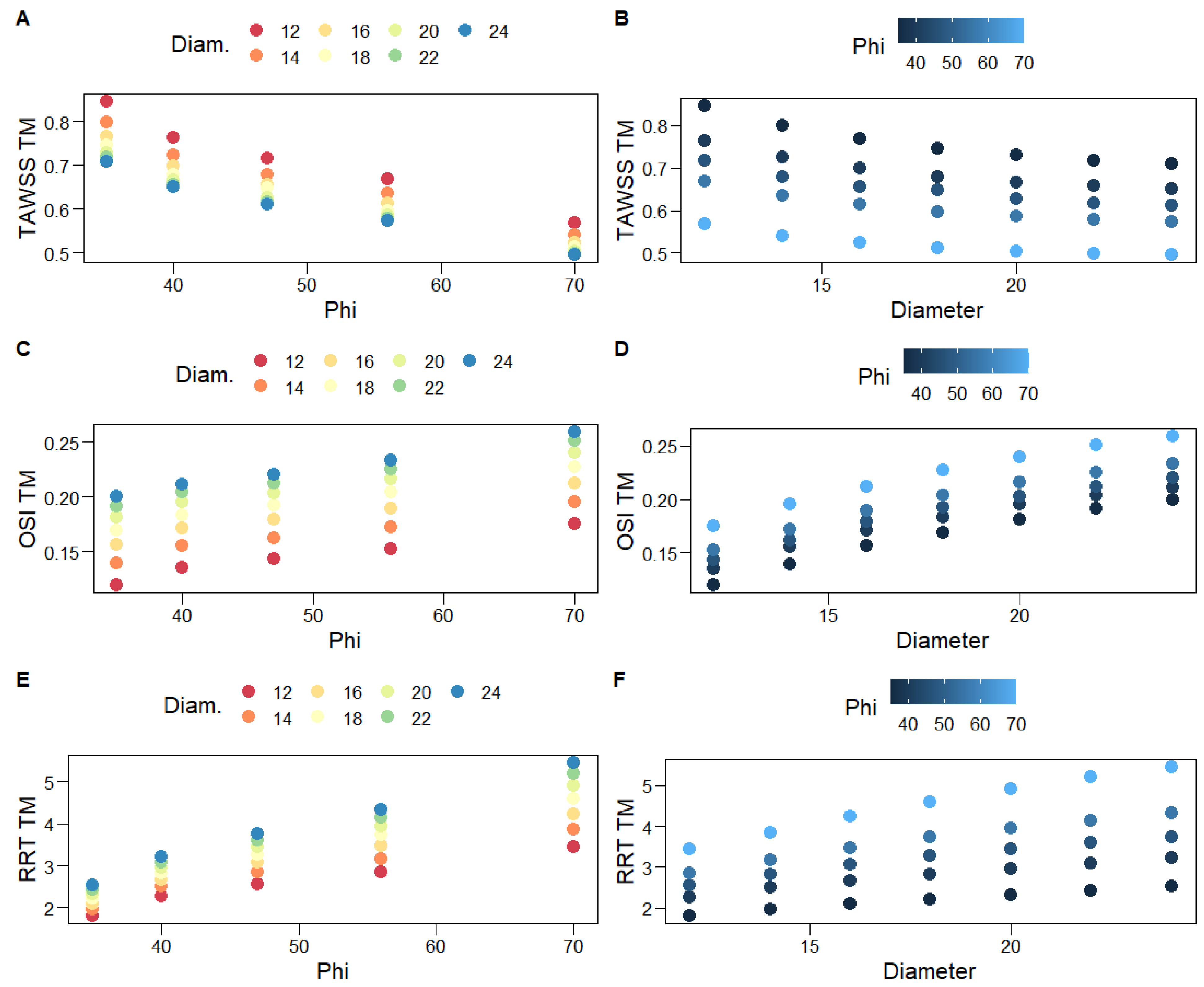
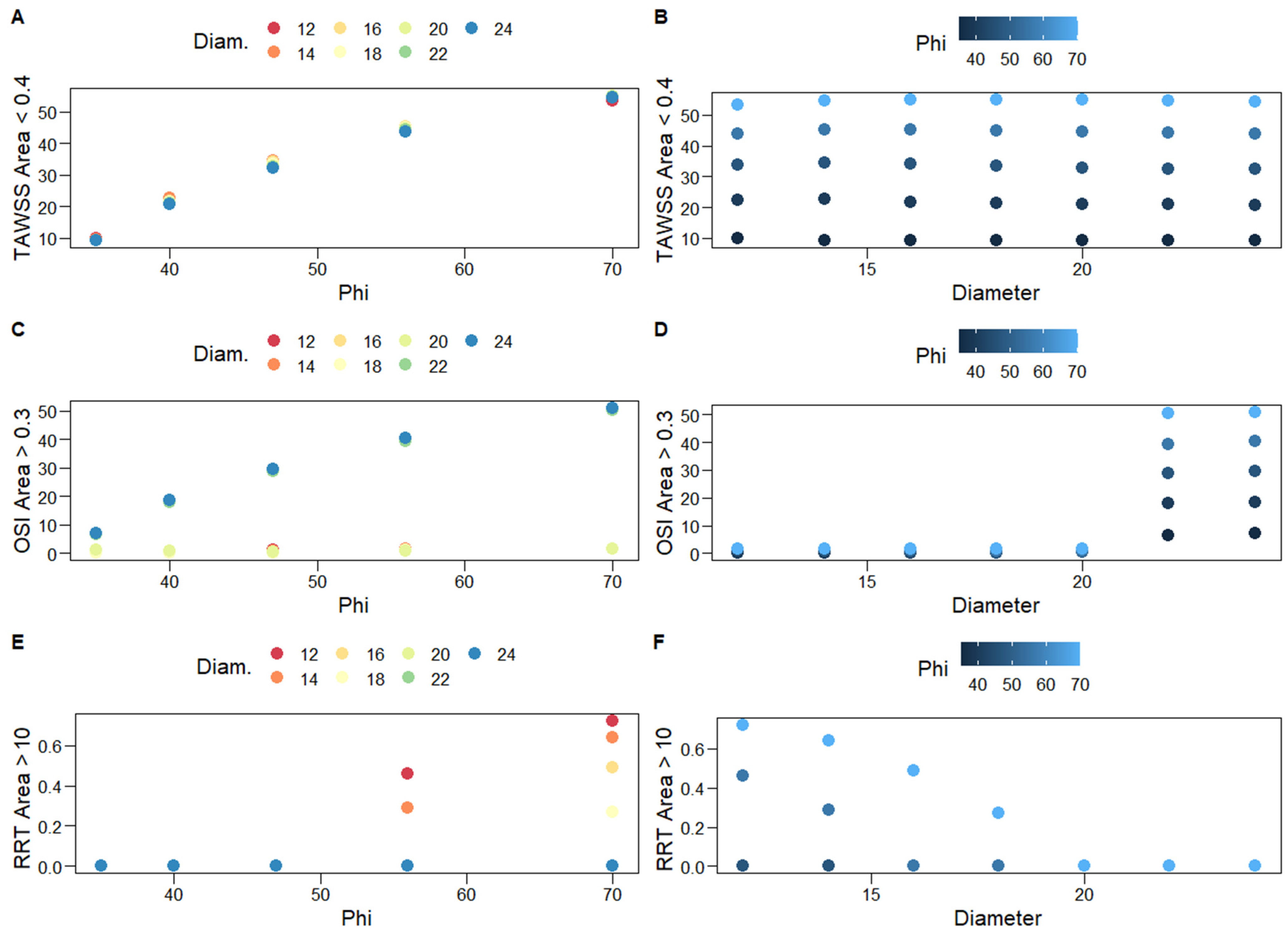
Figure 9 shows scatterplots for the associations of hemodynamic variables with graft limb angles, φ, and diameters, D. One can clearly observe the heteroscedastic, negative curvilinear relationship of TAWSSTM with both φ and D: the variance of the observed TAWSSTM decreases as φ and D increase. As expected, given the abovementioned, strong negative correlations for both OSITM and RRTTM are positively associated with φ and D. A general second-order specification, such as (8), is deemed adequate to capture the variability of the averaged hemodynamic variables. Indeed, the full second-order model explains the vast majority of the variability of TAWSSTM (Table 5). Limb angles constitute a relatively more important predictor, as a quadratic model solely based on φ explains approximately eight times the variability explained by a quadratic model based on D alone (Table 5). The opposite result is observed for OSITM; namely, graft diameters are more important relative to φ in explaining the variability of OSITM, although the optimal specification is linear; hence, it does not contain the φ2 term.
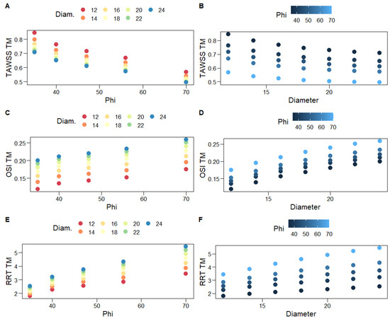
Figure 9.
Scatterplots for the associations of hemodynamic variables with graft limb angles, φ (A,C,E), and diameters, D (B,D,F). Different colors are used for increasing levels of D (A,C,E) and φ (B,D,F).

Table 5.
Coefficient estimates for the second-order regression model presented in (8); missing estimates correspond to terms that are eliminated from an AICc-based backward stepwise algorithm. Bootstrap-based standard errors are shown in parentheses. ΔAICc reports the difference in the levels of AICc, achieved from the final outcome of the model building procedure, relative to the full second-order specification. GoF is the goodness-of-fit metric that evaluates residual variance relative to the variance of the response (1 indicates the perfect fit of the examined model); MAD, an outlier-robust variance estimator is utilized to compute GoF. GoFφ (GοFD) is the GoF achieved by a quadratic model based on φ (D) alone.
The percentages of the total graft area with TAWSS < 0.4 Pa, OSI > 0.3, and RRT > 10 Pa−1, which correspond to thrombogenic stimulating environments, are reported in Table 4 and are depicted in Figure 8. The three percentages are positively correlated, albeit the bivariate association between the TAWSS < 0.4 Pa with the OSI > 0.3 percentages is not strong enough to be of statistical significance. In most simulation scenarios, the observed area percentages with RRT > 10 Pa−1 are negligible (Table 4, Figure 8); thus, second-order regression models are not applied in this case. Notably, very large percentages are only observed for large values of φ (56°, 70°) and D < 20 mm; the larger the diameter the worse the result, as the total area of the thrombogenic stimulating environment significantly increases. Similarly, percentages of the total graft area with OSI > 0.3 are negligible for grafts with D < 22 mm; the larger the diameter, the worse the result, with negligible effects of φ.
On the other hand, the percentages of the total graft area with TAWSS < 0.4 Pa clearly depend on limb angles (Figure 10A); a quadratic model based on φ alone practically captures all of their variability, whereas the diameter is not a significant predictor (Table 5). Specifically, the simple, φ-based quadratic model is shown below
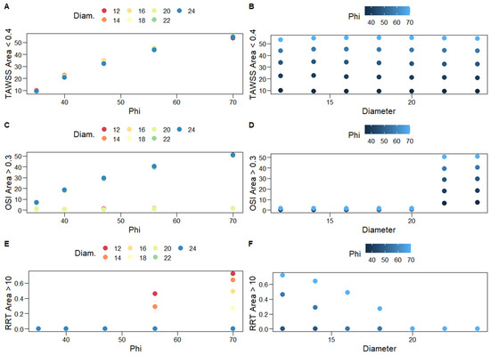
Figure 10.
Scatterplots for the associations of the percentages of the total graft area with TAWSS < 0.4 Pa (A,B), OSI > 0.3 (C,D), and RRT > 10 Pa−1 (E,F) (thrombogenic stimulating environments) with graft limb angles, φ, and diameters, D. Different colors are used for increasing levels of D (left column) and φ (right column).
The model explains approximately 97% of the variability of these percentages (bootstrap standard errors are presented in parentheses, below parameter estimates). This simple specification can be utilized to predict the percentages of the total graft area with TAWSS < 0.4 Pa for unobserved levels of φ, which lie within the examined levels (35–70°).
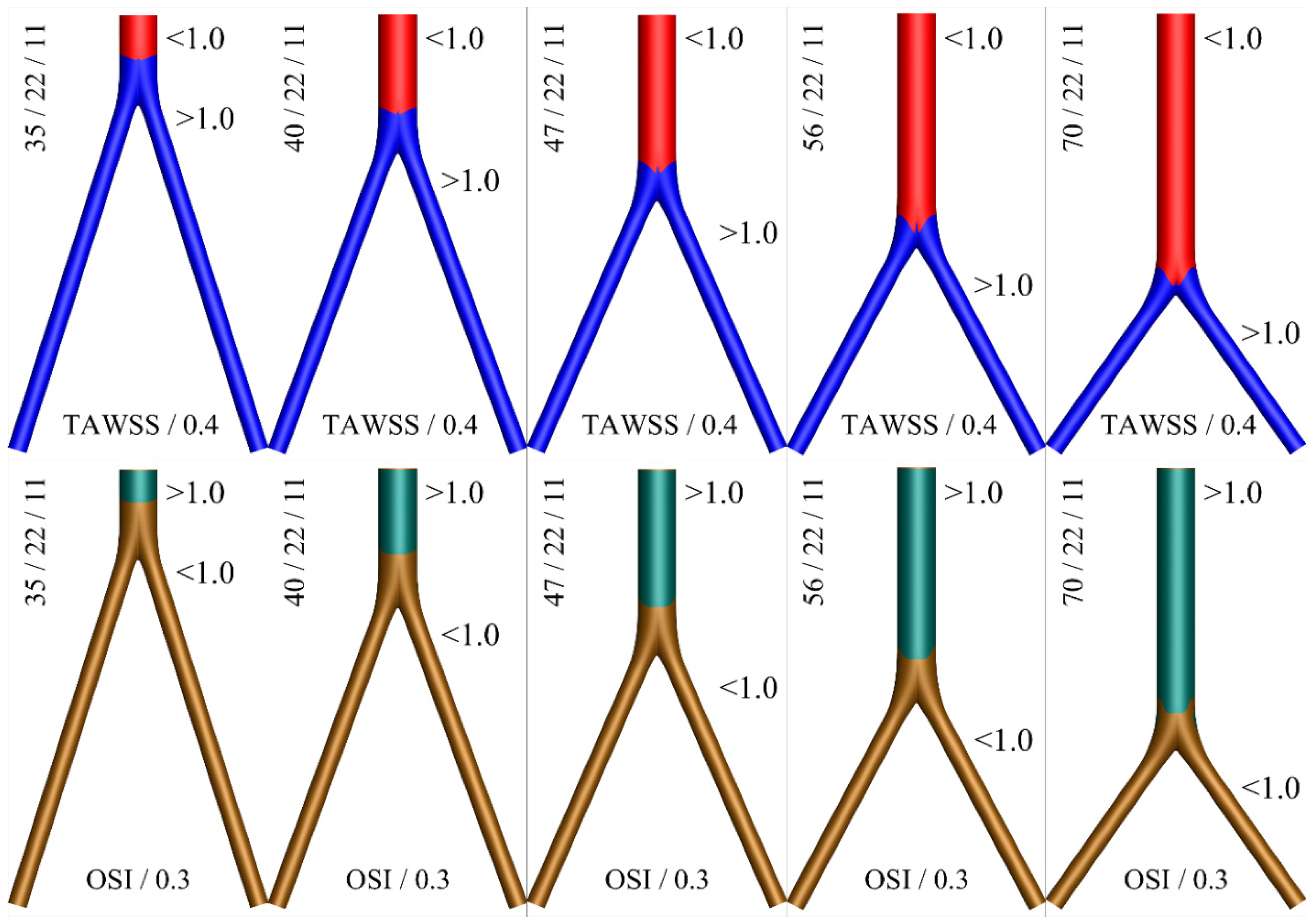
A color map displaying thrombogenic regions along the surface of the idealized geometries for various angles is shown in Figure 11. Based on this graphical representation, the hemodynamic advantage of the short main body (small angle φ) configuration can be observed.
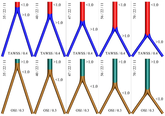
Figure 11.
Two color contours for thrombogenic conditions as expressed by the variables TAWSS/0.4 < 1 (top) and OSI/0.3 > 1 (bottom), for D = 2d = 22 mm. The (blue) red and (brown) green colors depict the (non) thrombus prone areas.
4. Discussion
This work is among the few that have utilized advanced, outlier-robust statistical models to analyze blood flow simulations [13,31]. The results presented in the previous section demonstrate that associations between response variables that summarize hemodynamics with a graft’s main characteristics, namely its limb angle and diameter, can be captured with second-order predictive specifications, which include interaction effects. On the other hand, simple linear models are inadequate in general for that purpose. Furthermore, Section 3 carries practical implications when alternative graft choices are available for a patient. Specifically, when accepted grafts only differ regarding their limb angles, it is clear that the one with the smallest φ should be selected; for all examined cases, our analyses revealed that the larger the angle, the larger the percentage of the total graft area that corresponds to the thrombogenic simulating environment. Similarly, when alternative accepted grafts only differ regarding their diameters, the one with the smallest diameter should be selected, especially if the set of accepted grafts includes cases with D > 20 mm, given the abrupt increase in thrombogenic areas observed in Table 4. Actually, Table 4 and Figure 10 strongly suggest against accepting grafts with D > 20 mm when the set of accepted grafts includes cases with smaller diameters. Obviously, when alternative accepted grafts differ regarding both angles and diameters, practitioners should choose the one that corresponds to minimum φ and D.
The abovementioned findings carry several clinical implications. First, regarding the open surgical reconstruction of aortic occlusive or aneurysmal disease, our results indicate that the proximal part of the bifurcated graft should be cut as short as possible, leaving two long distal limbs. This is the configuration that results in the smallest angle φ, which is hemodynamically advantageous. It should be stressed that these grafts are typically intra-operatively shaped by the operating physician. Thus, rendering a variety of different configurations is feasible, although there is currently no evidence to guide clinical practice and these configurations are interchangeably used [6]. A possible advantage of a longer parent tube outline would be the capability to use an aortic endograft in the case of a proximal or distal pseudoaneurysm in need of a secondary intervention. This is important in an era where endovascular techniques are constantly developing [32,33]. Nevertheless, the design of some of the modern endografts would make it possible for a main body length as short as 15 mm to be treated by endovascular means (i.e., the Altura endograft-Lombard Medical, Didcot, Oxfordshire, United Kingdom) [34,35].
Additionally, the diameter of the surgical graft is chosen based on the native aortic diameter, but again, a variety of choices could be deemed appropriate, without any evidence being available to guide physicians. According to the present results, the lowest diameter graft that would be considered suitable should be chosen. It should be noted that a previous publication from our group indicated that, in terms of the parent-to-daughter limb length ratio, a longer parent tube configuration could be advantageous from a hemodynamic perspective, due to the reduced overall hydraulic resistance, as calculated by Poiseuille’s law [6]. This analysis was hampered by the fact that Poiseuille’s law is an oversimplification of hemodynamic simulations, which does not apply to pulsatile flow conditions and non-Newtonian fluids. Therefore, the current approach is methodologically advantageous and more realistic, giving credibility to the present results.
Our findings may carry implications not only for open surgical repair, but also for the endovascular treatment of aortic pathologies. Currently, a variety of aortic modular endografts are used for the treatment of AAAs. Each system has its own anatomic requirements, but these are mostly similar between different devices. In many cases, a variety of devices can be used to treat a given aortic pathology, which are interchangeably used [35]. The design of these endografts can be grouped into three broad categories. The first and most common is where a short main body around 5 cm long splits to two iliac limbs [36]. The second uses an anatomical fixation of the main body into the native aortic bifurcation, where the main body has the length of the native infra-renal aorta [37]. The third is where there is no main body, just two limbs that are simultaneously deployed from the aortic neck to the common iliac arteries [34]. The findings of this work would favor the last design as being hemodynamically advantageous, while the design of anatomical fixation would be the least desirable from a hemodynamic perspective. Regarding the oversizing of endoluminal grafts into the proximal aortic neck to achieve adequate sealing, a 10–30% rate is typically used. Excessive oversizing has been proposed to result in neck-related complications; this could be hemodynamically unfavorable according to our findings [38].
As with the majority of studies, the design of the current work is subject to limitations. The first is the assumption that the vessel walls are rigid. Even though this may be close to reality, the expected effect of graft compliance is not considered. Secondly, additional geometric features, such as graft bending and twisting, as well as graft limb tortuosity, may also alter the presented results. The fact that simple idealized geometries have been taken into account limits the applicability of the present results, since other morphometric indices that might have a significant effect on the simulation results were discarded. Nevertheless, such a methodology is able to better delineate the effect of the different angles and diameters on hemodynamic simulations, which would not be possible in the presence of a plethora of confounding geometric variables encountered in patient-specific anatomies. Moreover, these are the only factors that the operating surgeon can modify, and therefore, the current methodology allowed a relevant and practical conclusion to be produced. Additionally, the flow split between the limbs is not expected to be exactly equal, but nevertheless, it still remains a reasonable assumption.
Finally, the set of thresholds that have been chosen to define a hemodynamically thrombogenic environment may be suboptimal due to the lack of an adequate definition in the existing literature. Indeed, the available data mostly refer to atherogenic hemodynamic conditions, which cause endothelial damage and favor the formation of atheromatous plaque. In the present study, this would not be relevant since the hemodynamic environment inside a graft is our main focus. Nevertheless, recent reports that have studied the potential for thrombus formation inside the branches of custom-made endografts used during EVAR suggest values close to those used in the present study [25,39]. Despite the variability of thresholds reported in previous studies, the values that have been selected here closely approximate those most commonly used in the literature. Future studies along the research path included here include a statistical analysis of the effects of the dimensions, morphology, and angle bifurcation on the hemodynamic change of different geometries, such as patient-specific aneurysms [40,41].
5. Conclusions
The current study examines the hemodynamic behavior of various bifurcated aortic grafts for varying levels of proximal/distal length ratios and limb angles. Thirty-five cases are simulated with computational fluid dynamics techniques, assuming a non-Newtonian blood behavior, described by the Carreau-Yasuda rheological model. Our results indicate that grafts characterized by the smallest possible diameter and limb angle present a hemodynamic advantage and should be preferred by practitioners and clinicians.
Author Contributions
Conceptualization, K.T., Y.K. and N.K.; methodology, K.T., Y.K., N.K. and C.V.I.; software, K.T.; writing—original draft, K.T., Y.K. and N.K.; writing—review and editing, K.T., Y.K., N.K. and C.V.I.; supervision, K.T. All authors have read and agreed to the published version of the manuscript.
Funding
This research received no external funding.
Institutional Review Board Statement
Not applicable.
Informed Consent Statement
Not applicable.
Data Availability Statement
Statistical investigations are fully reproducible as all produced and analyzed data are available upon request.
Acknowledgments
The authors would like to thank Antonios Karasavvidis, CFD Applications, Customer Service, BETA CAE Systems SA for many useful discussions on mesh building.
Conflicts of Interest
The authors declare no conflict of interest.
Nomenclature
| U | fluid velocity |
| P | fluid pressure |
| fluid density | |
| stress tensor | |
| shear rate | |
| μ | dynamic viscosity |
| T | period of cardiac cycle |
| CY | Carreau-Yasuda |
| ω | angular frequency |
| Bessel function | |
| Re | Reynolds number |
| α | Womersley number |
| WSS | Wall Shear Stress |
| TAWSS | Time Average Wall Shear Stress |
| OSI | Oscillatory Shear Index |
| RRT | Relative Residence Time |
| BL | Boundary Layer |
| L | distance between renal and femoral arteries |
| l | distance between femoral arteries and midline |
| AIC | Akaike Information Criterion |
| LAD | Least Absolute Deviations |
| MAD | Median Absolute Deviation |
| GoF | Goodness of Fit |
| GoFφ | Goodness of Fit based only on φ |
| GoFD | Goodness of Fit based only on D |
References
- Wanhainen, A.; Verzini, F.; Van Herzeele, I.; Allaire, E.; Bown, M.; Cohnert, T.; Dick, F.; van Herwaarden, J.; Karkos, C.; Koelemay, M.; et al. Editor’s Choice-European Society for Vascular Surgery (ESVS) 2019 Clinical Practice Guidelines on the Management of Abdominal Aorto-iliac Artery Aneurysms. Eur. J. Vasc. Endovasc. Surg. 2019, 57, 8–93. [Google Scholar] [CrossRef] [PubMed]
- Conte, M.S.; Bradbury, A.W.; Kolh, P.; White, J.V.; Dick, F.; Fitridge, R.; Mills, J.L.; Ricco, J.-B.; Suresh, K.R.; Murad, M.H.; et al. Global Vascular Guidelines on the Management of Chronic Limb-Threatening Ischemia. Eur. J. Vasc. Endovasc. Surg. 2019, 58, S1–S109.e33. [Google Scholar] [CrossRef] [PubMed]
- Norgren, L.; Hiatt, W.R.; Dormandy, J.A.; Nehler, M.R.; Harris, K.A.; Fowkes, F.G.R. on behalf of the TASC II Working Group. Inter-Society Consensus for the Management of Peripheral Arterial Disease (TASC II). J. Vasc. Surg. 2007, 45, S5–S67. [Google Scholar] [CrossRef]
- Georgakarakos, E.; Xenakis, A.; Georgiadis, G.S.; Argyriou, C.; Manopoulos, C.; Tsangaris, S.; Lazarides, M.K. Computational estimation of the influence of the main body-to-iliac limb length ratio on the displacement forces acting on an aortic endograft. Theoretical application to Bolton Treovance® Abdominal Stent-Graft. Int. Angiol. 2014, 33, 480–484. [Google Scholar]
- Georgakarakos, E.; Xenakis, A.; Georgiadis, G.S. Estimating the hemodynamic influence of variable main body-to-iliac limb length ratios in aortic endografts. Int. Angiol. 2018, 37, 41–45. [Google Scholar] [CrossRef]
- Kontopodis, N.; Tzirakis, K.; Stylianou, F.; Vavourakis, V.; Patou, G.M.; Ioannou, C.V. Should the proximal part of a bifurcated aortic graft be kept as short as possible? A computational study elucidates onaortic graft hemodynamics for various main body lengths. Ann. Vasc. Surg. 2022, 84, 344–353. [Google Scholar] [CrossRef] [PubMed]
- Georgakarakos, E.; Argyriou, C.; Schoretsanitis, N.; Ioannou, C.V.; Kontopodis, N.; Morgan, R.; Tsetis, D. Geometrical factors influencing the hemodynamic behavior of the AAA stent grafts: Essentials for the clinician. Cardiovasc. Interv. Radiol. 2014, 37, 1420–1429. [Google Scholar] [CrossRef] [PubMed]
- West, C.A., Jr.; Johnson, L.W.; Doucet, L.; Caldito, G.; Heldman, M.; Szarvas, T.; Speirs, R.D.; Carson, S. A contemporary experience of open aortic reconstruction in patients with chronic atherosclerotic occlusion of the abdominal aorta. J. Vasc. Surg. 2010, 52, 1164–1172. [Google Scholar] [CrossRef]
- Arzani, A. Accounting for residence-time in blood rheology models: Do we really need non-Newtonian blood flow modelling in large arteries? J. R. Soc. Interface 2018, 15, 20180486. [Google Scholar] [CrossRef]
- Cho, Y.I.; Kensey, K.R. Effects of the non-Newtonian viscosity of blood on flows in a diseased arterial vessel. Part 1: Steady flows. Biorheology 1991, 28, 241–262. [Google Scholar] [CrossRef]
- Weddell, J.C.; Kwack, J.; Imoukhuede, P.I.; Masud, A. Hemodynamic Analysis in an Idealized Artery Tree: Differences in Wall Shear Stress between Newtonian and Non-Newtonian Blood Models. PLoS ONE 2015, 10, e0124575. [Google Scholar] [CrossRef]
- Fisher, C.; Rossmann, J.S. Effect of non-newtonian behavior on hemodynamics of cerebral aneurysms. J. Biomech. Eng. 2009, 131, 091004. [Google Scholar] [CrossRef]
- Tzirakis, K.; Kamarianakis, Y.; Metaxa, E.; Kontopodis, N.; Ioannou, C.V.; Papaharilaou, Y. A robust approach for exploring hemodynamics and thrombus growth associations in abdominal aortic aneurysms. Med. Biol. Eng. Comput. 2017, 55, 1493–1506. [Google Scholar] [CrossRef]
- Valant, A.Z.; Ziberna, L.; Papaharilaou, Y.; Anayiotos, A.; Georgiou, G.C. The influence of temperature on rheological properties of blood mixtures with different volume expanders-implications in numerical arterial hemodynamics simulations. Rheol. Acta. 2011, 50, 389–402. [Google Scholar] [CrossRef]
- Fung, Y.C. Biomechanics: Mechanical Properties of Living Tissues; Springer: Berlin/Heidelberg, Germany, 1993. [Google Scholar]
- Tzirakis, K.; Kamarianakis, Y.; Kontopodis, N.; Ioannou, C.V. Classification of Blood Rheological Models through an Idealized Symmetrical Bifurcation. Symmetry 2023, 15, 630. [Google Scholar] [CrossRef]
- Pedley, T.J. The Fluid Mechanics of Large Blood Vessels; Cambridge University Press: Cambridge, UK, 1980. [Google Scholar]
- Olufsen, M.S.; Peskin, C.S.; Kim, W.Y.; Pedersen, E.M.; Nadim, A.; Larsen, J. Numerical simulation and experimental validation of blood flow in arteries with structured-tree outflow conditions. Ann. Biomed. Eng. 2000, 28, 1281–1299. [Google Scholar] [CrossRef]
- Womersley, J.R. Method for the calculation of velocity, rate of flow and viscous drag in arteries when the pressure gradient is known. J. Physiol. 1955, 127, 553–563. [Google Scholar] [CrossRef]
- He, X.; Ku, D.N. Pulsatile flow in the human left coronary artery bifurcation: Average conditions. J. Biomech. Eng. 1996, 118, 74–82. [Google Scholar] [CrossRef]
- Himburg, H.A.; Grzybowski, D.M.; Hazel, A.L.; LaMack, J.A.; Li, X.M.; Friedman, M.H. Spatial comparison between wall shear stress measures and porcine arterial endothelial permeability. Am. J. Physiol. Heart. Circ. Physiol. 2004, 286, H1916–H1922. [Google Scholar] [CrossRef]
- Malek, A.M.; Alper, S.L.; Izumo, S. Hemodynamic shear stress and its role in atherosclerosis. JAMA 1999, 282, 2035–2042. [Google Scholar] [CrossRef]
- Morbiducci, U.; Gallo, D.; Ponzini, R.; Massai, D.; Antiga, L.; Montevecchi, F.M.; Redaelli, A. Quantitative analysis of bulk flow in imagebased hemodynamic models of the carotid bifurcation: The influence of outflow conditions as test case. Ann. Biomed. Eng. 2010, 38, 3688–3705. [Google Scholar] [CrossRef] [PubMed]
- Suess, T.; Anderson, J.; Danielson, L.; Pohlson, K.; Remund, T.; Blears, E.; Gent, S.; Kelly, P. Examination of near-wall hemodynamic parameters in the renal bridging stent of various stent graft configurations for repairing visceral branched aortic aneurysms. J. Vasc. Surg. 2011, 64, 788–796. [Google Scholar] [CrossRef] [PubMed]
- Tran, K.; Feliciano, K.B.; Yang, W.; Schwarz, E.L.; Marsden, A.L.; Dalman, R.L.; Lee, J.T. Patient-specific changes in aortic hemodynamics is associated with thrombotic risk after fenestrated endovascular aneurysm repair with large diameter endografts. JVS Vasc. Sci. 2022, 3, 219–231. [Google Scholar] [CrossRef] [PubMed]
- De Santis, G.; Mortier, P.; De Beule, M.; Segers, P.; Verdonck, P.; Verhegghe, B. Patient-specific computational fluid dynamics: Structured mesh generation from coronary angiography. Med. Biol. Eng. Comput. 2010, 48, 371–380. [Google Scholar] [CrossRef] [PubMed]
- Burnham, K.P.; Anderson, J.R. Model Election and Multimodel Inference: A Practical Information-Theoretic Approach, 2nd ed.; Springer: Berlin/Heidelberg, Germany, 2003. [Google Scholar]
- Barton, K. MuMIN: Multi-Model Inference, R-Rackage Version 0.12.0. 2009. Available online: https://www.semanticscholar.org/paper/MuMIn-%3A-multi-model-inference%2C-R-package-version-Barton/af1086127738956d63fce81690819de979b6dfcf (accessed on 31 May 2023).
- Koenker, R. Quantile Regression (Econometric Society Monographs); Cambridge University Press: Cambridge, UK, 2005. [Google Scholar]
- Sheather, S.J. A Modern Approach to Regression with R; Springer Texts in Statistics; Springer Science & Business Media: New York, NY, USA, 2010. [Google Scholar]
- Tzirakis, K.; Kamarianakis, Y.; Kontopodis, N.; Ioannou, C.V. The Effect of Blood Rheology and Inlet Boundary Conditions on Realistic Abdominal Aortic Aneurysms under Pulsatile Flow Conditions. Bioengineering 2023, 10, 272. [Google Scholar] [CrossRef] [PubMed]
- Bosch, J.A.T.; Waasdorp, E.J.; de Vries, J.P.; Moll, F.L.; Teijink, J.A.; van Herwaarden, J.A. The durability of endovascular repair of para-anastomotic aneurysms after previous open aortic reconstruction. J. Vasc. Surg. 2011, 54, 1571–1578. [Google Scholar] [CrossRef]
- Wu, Z.; Xu, L.; Raithel, D.; Qu, L. Endovascular repair of proximal para-anastomotic aneurysms after previous open abdominal aortic aneurysm reconstruction. Vascular 2016, 24, 227–232. [Google Scholar] [CrossRef]
- Krievins, D.; Krämer, A.; Savlovskis, J.; Oszkinis, G.; Debus, E.S.; Oberhuber, A.; Zarins, C.K. Initial Clinical Experience Using the Low-Profile Altura Endograft System with Double D-Shaped Proximal Stents for Endovascular Aneurysm Repair. J. Endovasc. Ther. 2018, 25, 379–386. [Google Scholar] [CrossRef]
- Kontopodis, N.; Galanakis, N.; Tzartzalou, I.; Tavlas, E.; Georgakarakos, E.; Dimopoulos, I.; Tsetis, D.; Ioannou, C.V. An update on the improvement of patient eligibility with the use of new generation endografts for the treatment of abdominal aortic aneurysms. Expert Rev. Med. Devices 2020, 17, 1231–1238. [Google Scholar] [CrossRef]
- Georgakarakos, E.; Papatheodorou, N.; Argyriou, C.; Tasopoulou, K.M.; Doukas, D.; Georgiadis, G.S. An update on the ovation abdominal stent graft for the treatment of abdominal aortic aneurysms: Current evidence and future perspectives. Expert Rev. Med. Devices 2020, 17, 1249–1256. [Google Scholar] [CrossRef]
- İşcan, H.Z.; Karahan, M.; Akkaya, B.B.; Başar, V.; Aşkın, G.; Kubat, E.; Aytekin, B.; Ünal, E.U. Long-term results of endovascular intervention with unibody bifurcation endograft for elective abdominal aortic aneurysm management. Rev. Cardiovasc. Med. 2021, 22, 453–459. [Google Scholar] [CrossRef]
- Van Prehn, J.; Schlösser, F.J.; Muhs, B.E.; Verhagen, H.J.; Moll, F.L.; van Herwaarden, J.A. Oversizing of aortic stent grafts for abdominal aneurysm repair: A systematic review of the benefits and risks. Eur. J. Vasc. Endovasc. Surg. 2009, 38, 42–53. [Google Scholar] [CrossRef]
- Liu, M.Y.; Jiao, Y.; Liu, J.; Zhang, S.; Li, W. Hemodynamic Parameters Predict In-stent Thrombosis After Multibranched Endovascular Repair of Complex Abdominal Aortic Aneurysms: A Retrospective Study of Branched Stent-Graft Thrombosis. Front. Cardiovasc. Med. 2021, 8, 654412. [Google Scholar] [CrossRef]
- Gholampour, S.; Mehrjoo, S. Effect of bifurcation in the hemodynamic changes and rupture risk of small intracranial aneurysm. Neurosurg. Rev. 2021, 44, 1703–1712. [Google Scholar] [CrossRef]
- Hajirayat, K.; Gholampour, S.; Sharifi, I.; Bizari, D. Biomechanical Simulation to Compare the Blood Hemodynamics and Cerebral Aneurysm Rupture Risk in Patients with Different Aneurysm Necks. J. Appl. Mech. Tech. Phys. 2017, 58, 968–974. [Google Scholar] [CrossRef]
Disclaimer/Publisher’s Note: The statements, opinions and data contained in all publications are solely those of the individual author(s) and contributor(s) and not of MDPI and/or the editor(s). MDPI and/or the editor(s) disclaim responsibility for any injury to people or property resulting from any ideas, methods, instructions or products referred to in the content. |
© 2023 by the authors. Licensee MDPI, Basel, Switzerland. This article is an open access article distributed under the terms and conditions of the Creative Commons Attribution (CC BY) license (https://creativecommons.org/licenses/by/4.0/).

