1. Introduction
Pd-based membrane reactors are strongly recognized as an effective way to boost H
2 yield and natural gas (NG) conversion at low temperatures, compared to conventional steam reforming plants for hydrogen production [
1,
2,
3,
4,
5].
Indeed, the NG steam reforming (CH4 + H2O = CO + 3H2) is an endothermic reaction (ΔH0298K = 206 kJ/mol) and is limited by chemical equilibrium. This means that operation at high temperatures (850–900 °C) are required to reach significant hydrogen yields. In order to supply the reaction heat duty, a stream of NG is typically burned in the steam reforming furnace, thereby determining a reduction of the overall process efficiency as well as an increase in CO2 emissions.
Under such a scenario, the coupling of the steam reforming unit with a Pd-based hydrogen-selective membrane can provide for the following benefits: (i) enhancement of hydrogen yield and process efficiency at low temperatures, since the continuous selective removal of hydrogen from reaction environment allows maintaining the gas mixture composition far from equilibrium one; (ii) replacement of the high-temperature flue gases used in the furnace with a cleaner energy source or with waste heat available from another process; (iii) use of cheaper steel alloys for the fabrication of the reforming tube instead of the expensive materials currently used to withstand the high operating temperatures of conventional steam reforming plants.
KT—Kinetics Technology has gained an impressive experience over the last 15 years in the design and operation of innovative pilot plants, membrane reformers-based, for the production of pure hydrogen [
6,
7,
8,
9,
10,
11]. In particular, a pilot unit of 20 Nm
3/h of pure hydrogen has been designed and tested for more than 3000 h in a relevant industrial environment with NG supplied from the town grid, with a basic configuration characterized by sequential steps of reaction and membrane separation, in order to achieve the overcoming of thermodynamic equilibrium, while maintaining at the same time slightly decoupled operating conditions for a reformer and a membrane module, thereby avoiding a great deal of thermal stress for Pd-based membranes. The former proposed configuration, even not totally in line with the process intensification concept, represents a more simplified membrane reactor concept, where the membrane reactor in principle does not suffer from engineering design challenges and accordingly might boost the industrial acceptance of the novel technology in the first phases of transition to it.
Over the last few years, with the aim to further reduce the CO
2 emissions, typical of the highly energy-intensive processes of the hydrocarbon industry, attention has been focused by the Company on the application of solar energy as a renewable energy source, with the possibility to exploit it with molten salts having the role of heating medium and energy vector. The integration between the solar plant and industrial processes is widely studied all over the world [
12,
13,
14,
15]. For instance, Concentrating Solar Power (CSP) offers an attractive option to power industrial-scale desalination plants requiring thermal and electrical energy. Integration of CSP with multi-effect distillation (MED) and Reverse Osmosis (RO) seems to be cheaper than photovoltaic (PV) systems [
16]. Another potential application of solar energy is to power chemical processes when a high thermal duty is required: this is the case for endothermic reactions, which are a very promising opportunity for the production and storage of usable energy, and mitigation of CO
2 emissions.
Therefore, the aim of this paper is to report the experimental activities performed by the KT—Kinetics Technology-controlled company Processi Innovativi in the framework of the EU Project CoMETHy (Compact Multifuel Energy To Hydrogen conversion) in this field, studying the coupling of an integrated membrane reformer with solar-assisted molten salts heating, with the operation of a pilot unit specifically designed to this aim. The main feature of such a reactor is the complete integration of catalyst and membranes in only one vessel according to the process intensification concepts [
17].
An economic analysis has been also carried out, in order to check the industrial feasibility of the option to provide for a competitive novel technology at reduced environmental impact.
2. Experimental: Pilot Plant Description
The pilot plant was designed for a capacity of 3 Nm
3/h of pure hydrogen. The facility is available at ENEA Casaccia premises, and the process scheme of the pilot unit is reported in
Figure 1.
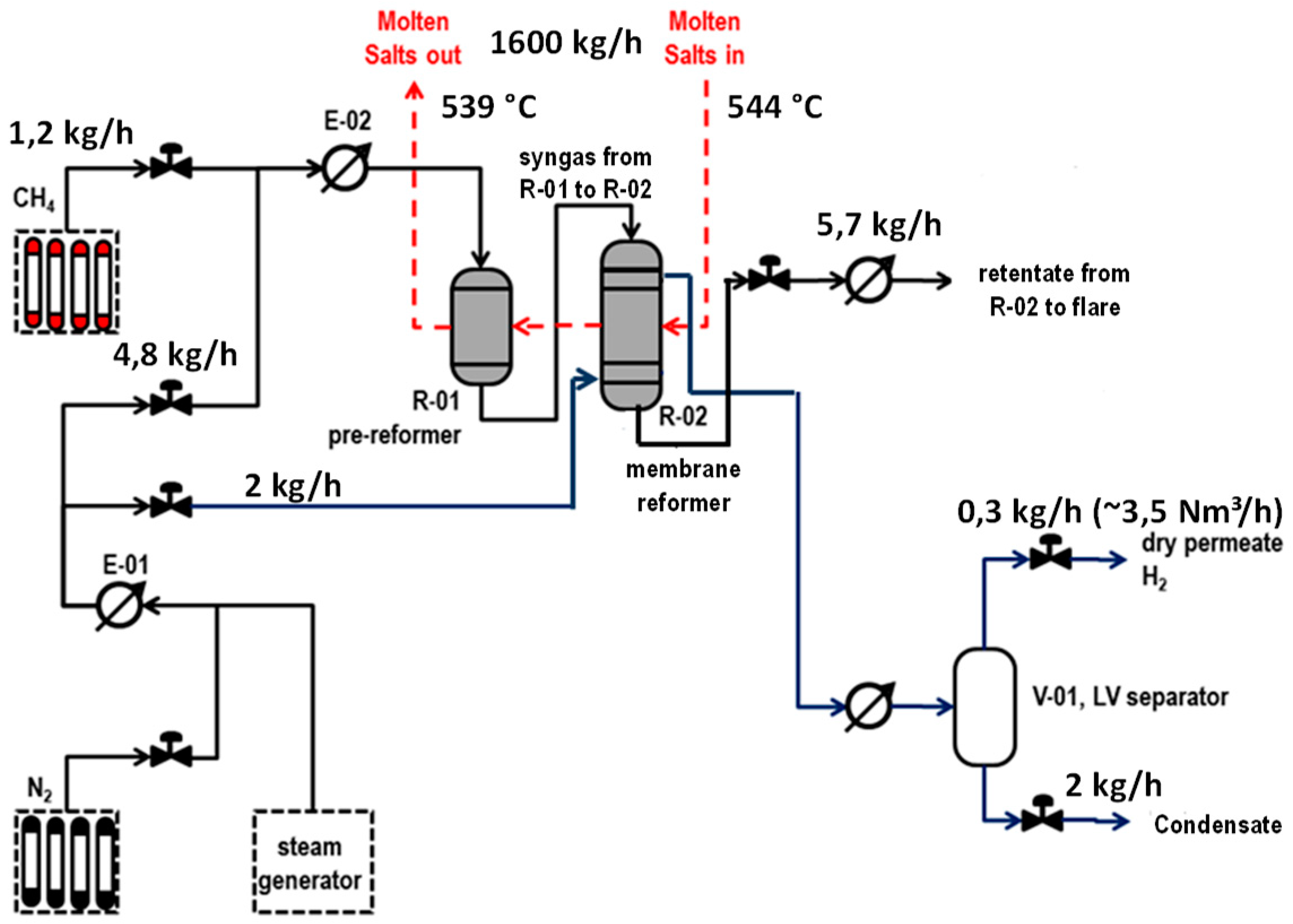
The plant architecture is based on a first prereformer stage (R-01) placed upstream to an integrated membrane reactor (R-02). Methane is supplied by pressurized gas cylinders. A process steam and a sweep steam for membranes are produced with a dedicated electrical boiler. Reaction heat to R-01 and R-02 is supplied through a molten salts mixture fed to R-02 at a maximum inlet temperature of 550 °C and further routed to the R-01.
Molten salts are countercurrently flowing through the two reactors, entering first R-02 at the desired temperature and flow rate. Molten salts are stored in a tank and pumped at the desired flow rate through an electrical heater, where the desired temperature is applied before being sent to the chemical test section. Due to the relatively low thermal duty of the reactors, the molten salts return temperature from the test section was just about 10 °C lower than the molten salts supply temperature. For this reason, in order to maintain a temperature lower than 500 °C inside the molten salts tank, a fraction of the heat from the back stream was recovered by heating the molten salts stream from the tank, and finally the temperature was further reduced by means of an air cooler.
In the prereformer stage of R-01, a partial methane conversion occurs, and accordingly the produced syngas mixed with unconverted methane routed to R-02 contains a certain amount of hydrogen, allowing membrane in R-02 to be active just at the inlet of reactor.
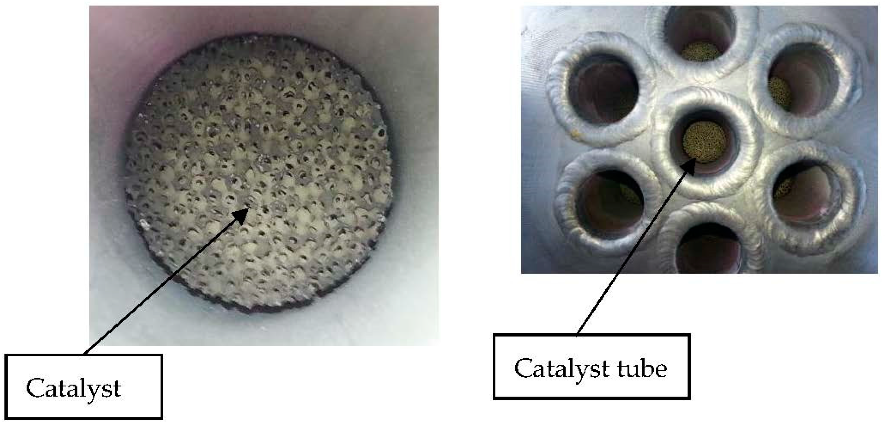
R-01 was designed in a shell and tube configuration where molten salts mixture flows in the shell side supplying reaction heat, and catalysts are installed inside tubes (
Figure 2).
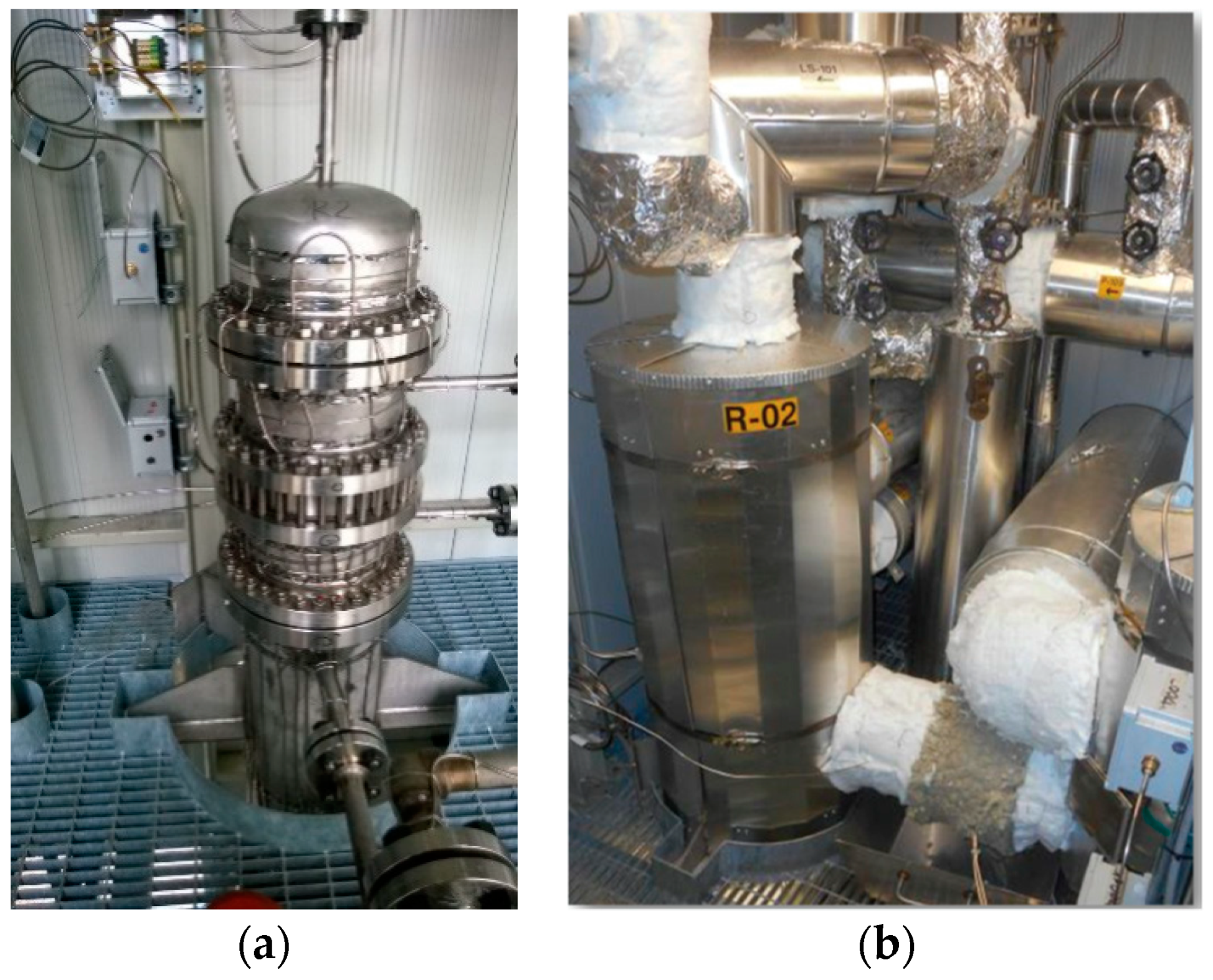
R-02 was also designed in a shell and tube configuration (
Figure 3).
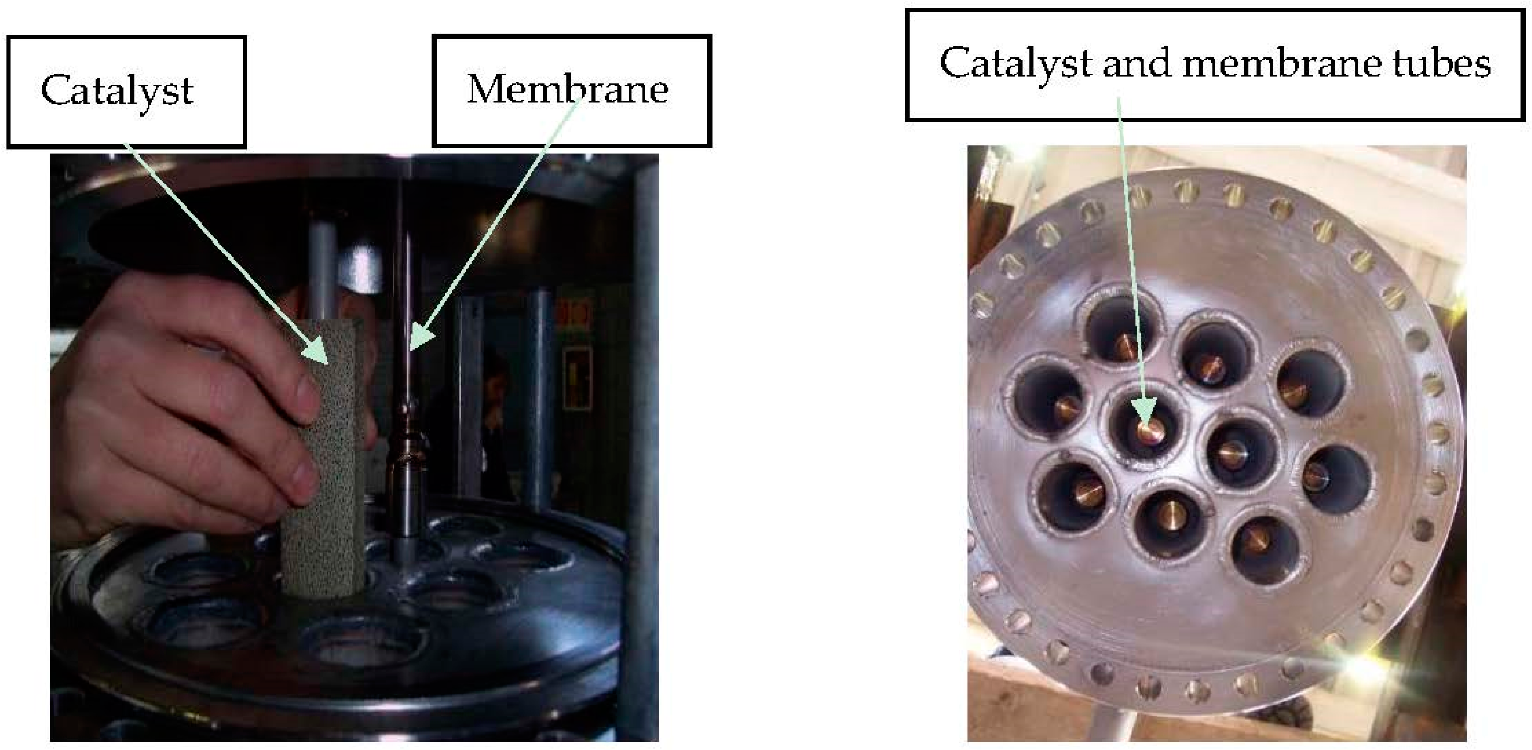
The main difference with the R-01 reactor is that in particular in R-02, catalysts and membranes are arranged according to a tube-in-tube configuration with catalysts in the annular section around the membrane tube (
Figure 4). The latter is equipped with an inner tube to allow for sweep gas flow on the permeate side.
Ten Pd-based membrane tubes are installed in R-02, with a permeate stream collected from R-02 and cooled down in order to easily separate sweep gas as condensate.
The installed membranes were provided by ECN (Energy Research Centre of the Netherlands) and they had an outside diameter of 14 mm and a length of 80 cm for an overall area of about 0.35 m
2. The main characteristics of the membranes are reported in
Table 1.
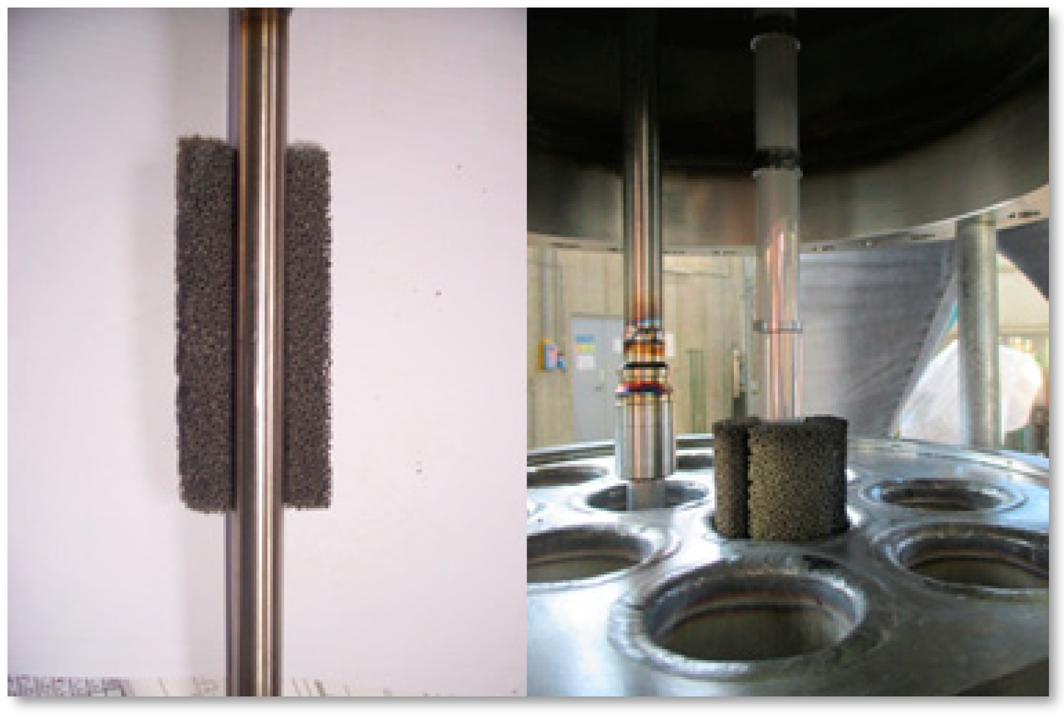
A bifunctional catalyst, nickel-noble metals-based, deposited on silicon carbide foam, is installed in both R-01 and R-02 reactors separately, shaped in the form of cylinder for R-01 (
Figure 2) and annular cylinder for R-02 wrapped around the membrane tube (
Figure 5).
The catalysts were prepared at the ProCeed Lab of the University of Salerno. To improve membrane separation efficiency, a superheated steam is used as a sweep gas in a countercurrent configuration. Reactors R-01/R-02 and piping in contact with molten salts are electrical traced, in order to assure, during the start-up and shut down procedures, temperature above the salts freezing point.
The main operating conditions of the catalytic tests carried out with the integrated membrane reactor are reported in
Table 2.
For the calculation of heat and material balances of the pilot plant, each of these units was modeled with Aspen Plus 9.0 as a standard process simulator. For the integrated membrane reactor simulation, ASPEN Plus 9.0 was combined with the kinetic equations reported by Xu and Froment [
18] and membrane permeation derived on Pd membranes coming from the same supplier and tested by the authors in the framework of previous experimental activities.
3. Results and Discussion
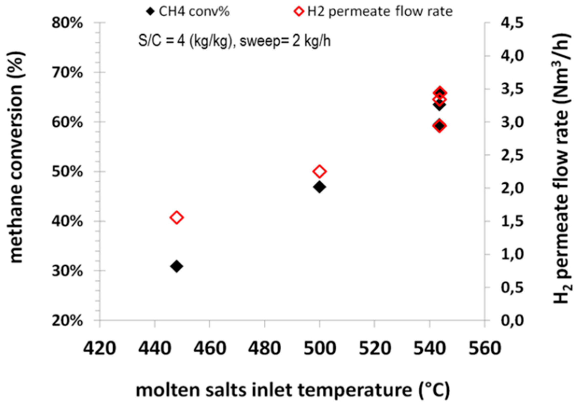
Different parameters were considered for the performance evaluation of the integrated system, such as the molten salts temperature, sweep steam flow rate and steam-to-carbon ratio. The effects of molten salts temperature on the methane conversion and the permeate H
2 flow rate at an operating pressure of 8.5 barg are reported in
Figure 6.
It can be observed that by increasing the molten salts temperature, the methane conversion increases since the endothermic reforming reaction is promoted at high temperatures, with CH4 conversion increasing from around 30% at 450 °C to around 60% at 540 °C. Obviously, the same trend can be observed for the flow rate of hydrogen permeating through the Pd membranes. At 540 °C, a permeate hydrogen flow rate of around 3.5 Nm3/h of hydrogen can be observed. It is also of interest the low CO concentration can be detected on the permeate side. Such values in consequence of the low level in the retentate side are in order of 12 ppmv (dry basis) at 450 °C and about 50 ppmv (dry basis) at 540 °C. The increase of CO concentration on the permeate side is in line with the occurrence of water gas shift more promoted at lower temperatures, thereby reducing the CO content on the retentate side and accordingly the CO detected on the permeate side. In terms of permeate purity, all tests accounted for an average H2 content higher than 99.8% mol (dry basis).
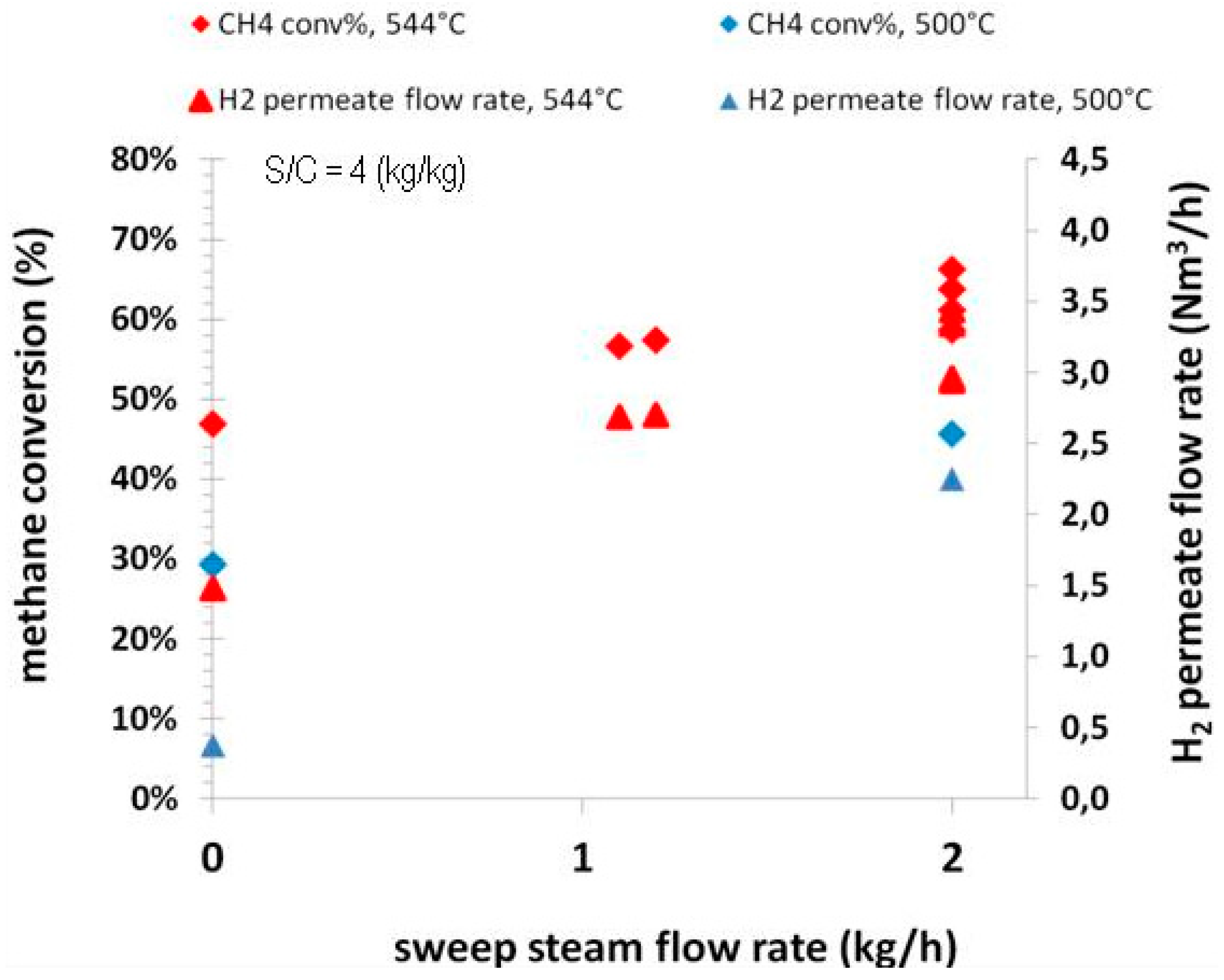
The effects of the sweep gas flow rate on the methane conversion and the permeate H
2 flow rate are reported in
Figure 7 for two operating temperatures, 544 °C and 500 °C, respectively, at an operating pressure of 8.5 barg.
For both operating temperatures, an increase in methane conversion and accordingly in the permeate H2 flow rate can be observed with increasing of the sweep gas flow rate, since a higher value for the latter parameter enables a higher driving force across the membrane. However, it is important to observe that the strongest effect can be checked when the sweep gas flow rate is increased up to 1 kg/h. At higher flow rates, the impact is more negligible. At about 1 kg/h of sweep gas flow rate, the hydrogen recovery is around 70% at 544 °C. A productivity of H2 of 1.5 Nm3/h can be obtained, even in absence of sweep gas on the permeate side.
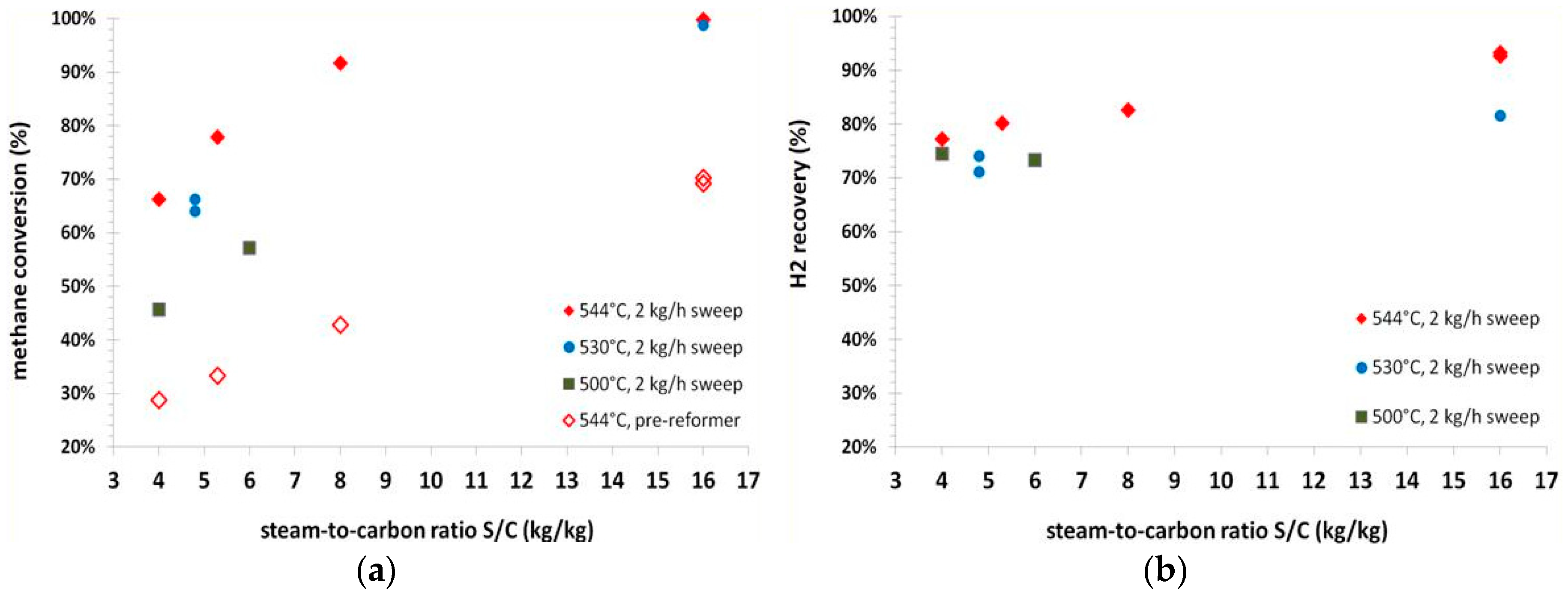
The effects of steam-to-carbon ratio on methane conversion and H
2 recovery are reported in
Figure 8, at the three operating temperatures of 500 °C, 530 °C, 544 °C and an operating pressure of 8.5 barg. The sweep gas flow rate was kept constant at 2 kg/h.
An increase in methane conversion can be observed with increasing of the steam-to-carbon ratio in the feed. The effect is more pronounced at low temperatures. At the highest steam-to-carbon ratio investigated of 16 (on weight basis), a methane conversion of 99% can be detected at 544 °C. In terms of hydrogen recovery, in this condition, it is possible to achieve a recovery of more than 90%.
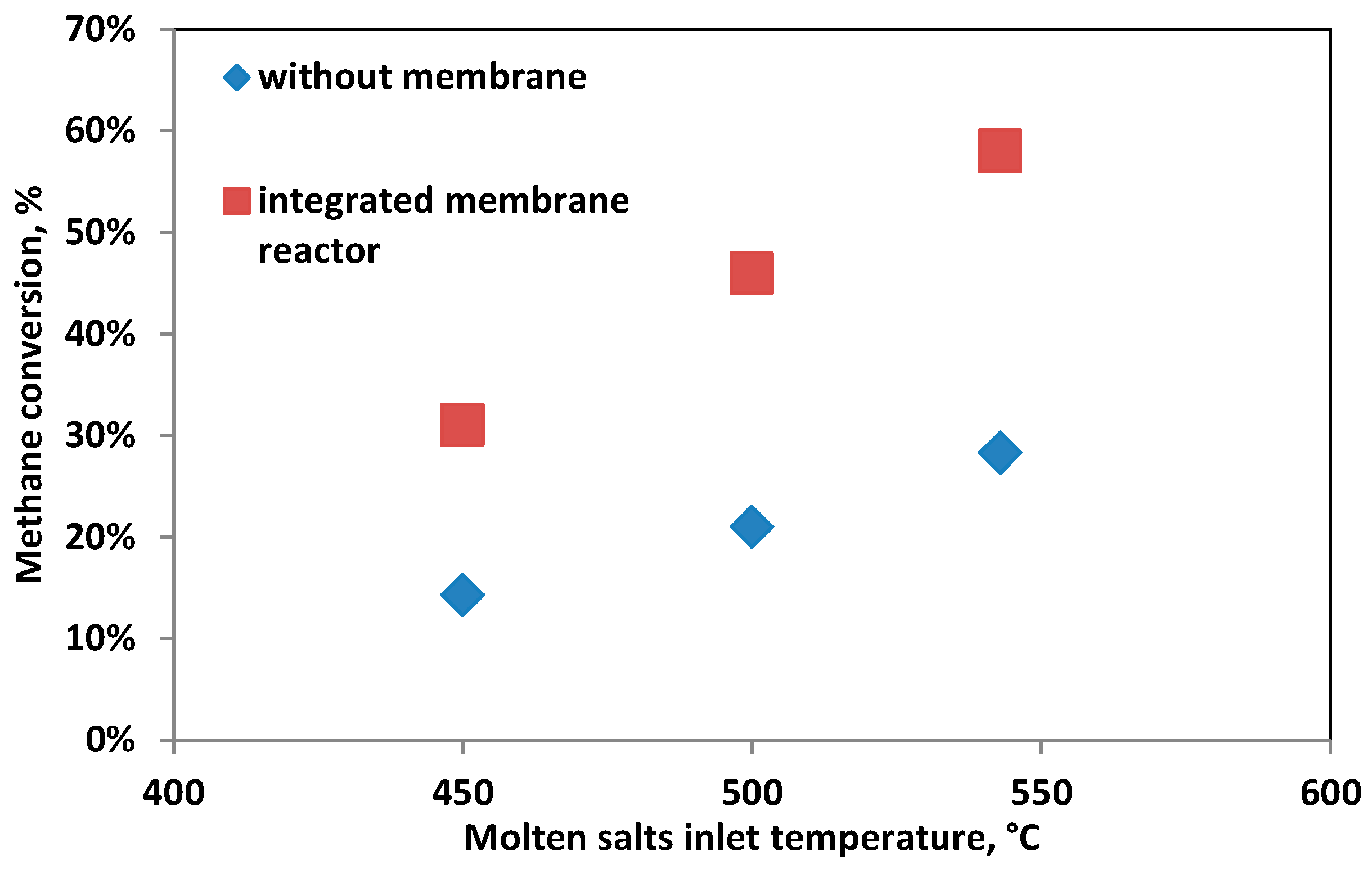
The performance comparison of the integrated membrane system with the thermodynamic equilibrium without a membrane is reported in
Figure 9, at a feed pressure of 8.5 barg and a steam-to-carbon ratio of 4 (on weight basis).
An overall feed conversion of 58% can be achieved at 543 °C, doubling the conversion that can be achieved in a conventional reformer at the same temperature.
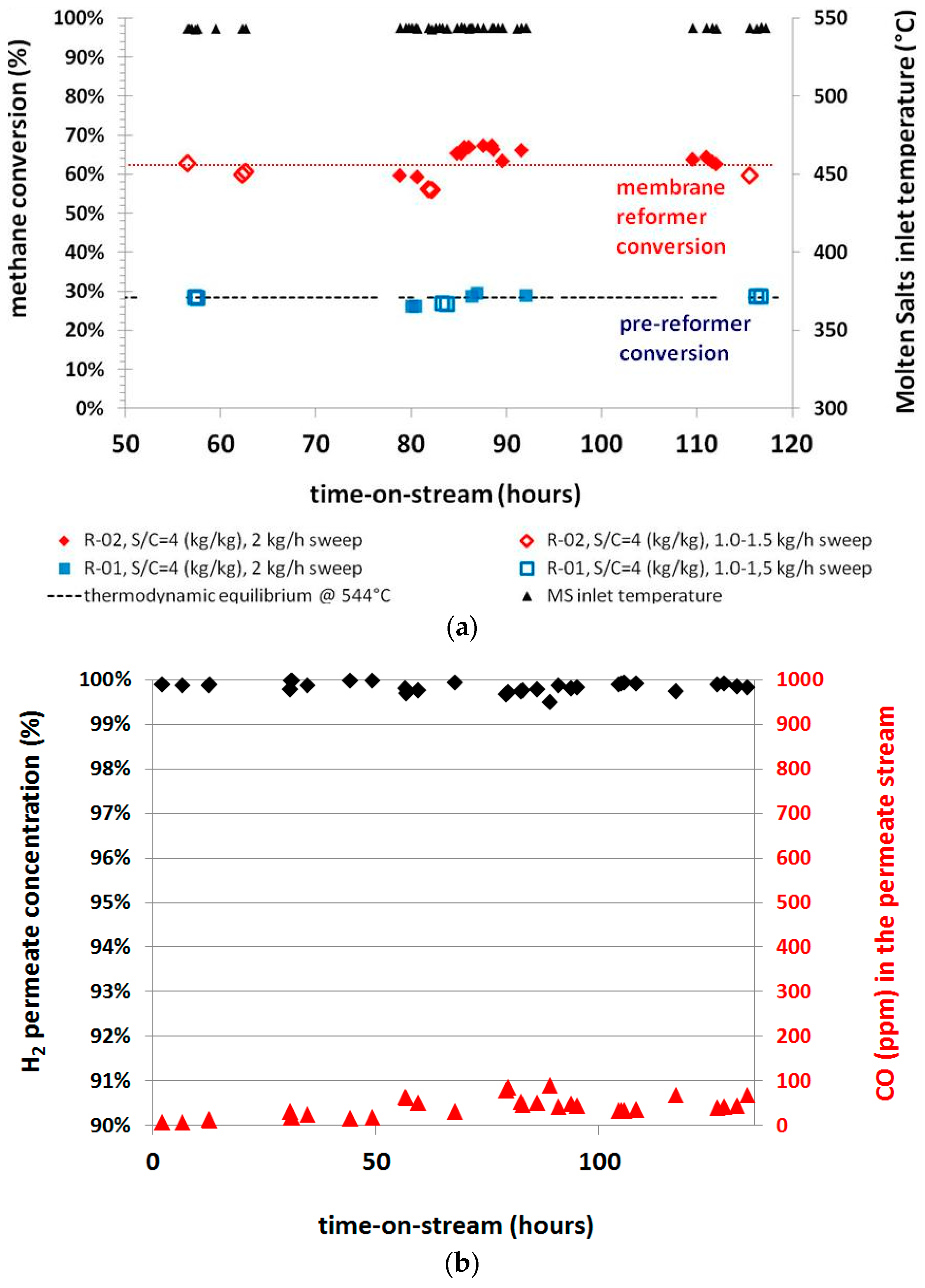
The system performance was also investigated in time-on-stream tests, in order to check its potential feasibility at industrial conditions. The results in terms of the methane conversion and the permeate hydrogen concentration are reported in
Figure 10.
The system performance is very stable for more than 100 h of continuous operation and no macroscopical signs of reactor performance loss have been evidenced over the experimental operation period, despite handling of catalysts and membranes and the several switches of operative conditions. The achieved results confirm the potentiality of the solution for application at industrial conditions; even if this concept is further assessed, it would be important to check the behavior of the membrane-catalyst coupling for at least 1000 h of continuous operation. Indeed, this order of magnitude of stability time is usually required for the catalyst at an accepted industrial level. In this way, if the stability of the membrane and that of catalyst are aligned to such order of magnitude, this allows to avoid too many frequent shut down operations of the plant for any procedure of maintenance or replacement of key components.
4. Economic Analysis
In order to make a preliminary economic analysis about the potentiality of the solar energy coupling with membrane reactors at an industrial capacity of 5000 Nm3/h of hydrogen, for the sake of simplicity, it was assumed to operate with a six-step membrane reactor in an open architecture, where reactions stages are followed by membrane stages.
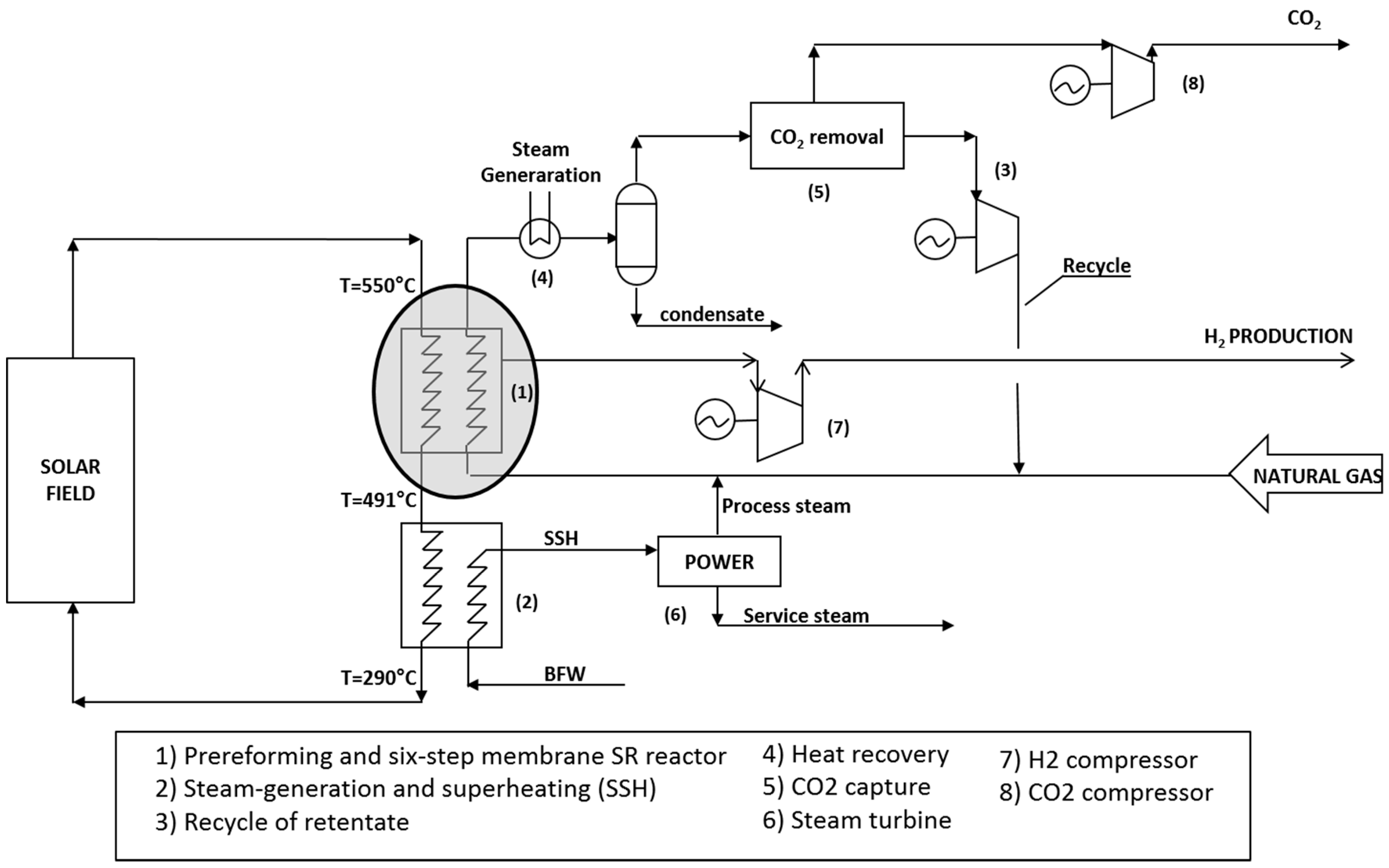
A process arrangement has been studied in order to realize a high-energy-efficiency process coupled with a low hydrogen production cost and CO
2 removal, based on the work proposed by Atsonios et al. [
19]. The process scheme considered with CO
2 capture in pre-combustion is reported in
Figure 11. The main units are represented by: (i) the multistep membrane steam reformer, (ii) product compression, (iii) power island. Each of these units was modeled with a standard process simulator.
The rate of hydrogen removed with a Pd/Ag membrane is described by the Hydrogen Recovery Factor (HRF), which is strongly correlated with the total installed membrane area, the pressure at the permeate side, and that at the retentate side. The pressure at the feed side was set to be equal to 9.2 barg, and meanwhile, the permeate side was kept at 0.7 barg. A low-pressure steam extracted from the steam cycle was used as a sweep gas to reduce hydrogen partial pressure. A sweeping steam was added in order to have an equimolar mixture of hydrogen and steam on the permeate side. The HRF (Hydrogen Recovery Factor) was kept constant in our simulation and equal to 90% (overall).
The solar field was designed for heat molten salts with a temperature up to 550 °C. Molten salts are fed to a steam reforming section composed by a pre-reformer and a six-step membrane Steam Reforming reactor. The outlet temperature of molten salts exiting the reaction section is 490 °C, so they can be used to produce the process steam required for the steam reforming reaction and the sweeping steam to be used at the membrane separation stage: additional steam is produced and used to generate power in a steam turbine.
Excess power is then exported. Molten salts are then forwarded to the solar field at a temperature of 290 °C. The NG is mixed with steam and sent to the reaction section; the produced hydrogen is recovered by membranes and then compressed to a pressure of 20 barg. The retentate is cooled down to generate steam (heat recovery) and then, after a CO
2 removal stage through a conventional amine unit, compressed and recirculated to the SR section. In this way, such a scheme achieves the complete conversion of NG in H
2 and CO
2. The total duty provided by the solar field is 16.7 MMkcal/h, much larger than what is required by the reforming section. The specific export of power was calculated in 0.4 kWh/Nm
3 of produced hydrogen for an overall production of 2 MWh. The membrane area was estimated at 976 m
2. In the calculation, a 5 μm thick larger of Pd/Ag23 wt% with a permeability of 30 Nm
3/h m
2 bar
0.5 and H
2/CO minimum selectivity of 200 was assumed [
6].
The cost of production (COP) per Nm
3 of H
2 produced was calculated by adding the capital expenditure (CAPEX) and the operating expenditure (OPEX) costs. No benefit was taken for CO
2 reduction emission. In addition, it is assumed that SR reactor is powered with a molten salts flow heated with solar energy for 5000 h/year, and in the remaining period of time, 3400 h/year, molten salts are heated through a process heater where NG is fired. Parameters used for economic analysis are reported in
Table 3.
Table 4 reports, together with operating conditions, the relevant COP for the innovative scheme compared with a conventional steam reformer scheme, where reaction duty is provided by purge gas from pressure swing adsorption (PSA) and additional fuel gas. The plant architecture is that it provides the steam required by the reboiler of the CO
2 recovery unit.
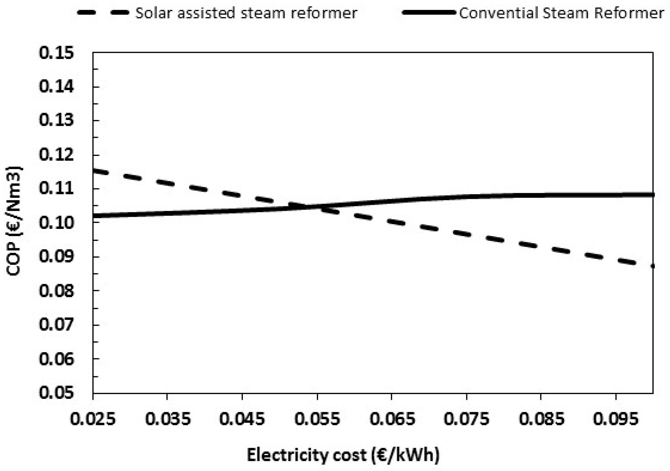
It is quite evident that the innovative scheme is interesting and that the membrane assisted H2 production powered by solar energy, and coupled with CO2 removal may already compete with conventional steam reforming if electricity price is high enough.
In this regard, by increasing the electricity price, the difference in COP between the conventional scheme and the molten salts-based SR is higher at a higher electricity price. Anyway, as shown in
Figure 12, the two configurations become equivalent at an electricity price much lower than current values.
It is also important to note that in conventional technology, about 70% of the production costs are related to the variable costs. The situation is quite different for the innovative scheme, where more than 55% of COP is related to the CAPEX and then only 45% is related to OPEX. Such a difference implies that, if accelerated depreciation is applied, production costs of a scheme will be more affected than for the conventional SR technology. In particular, it is calculated that the break-even point is reached at a depreciation factor of 7; with a depreciation factor of 12, the difference becomes even more important, reaching almost 15%.
5. Conclusions
The performance of a compact membrane reactor for steam reforming coupled with solar energy has been evaluated at a pilot level. The membrane reactor has been designed to integrate structured catalysts and Pd-based membranes with an overall thermal sustainment provided by solar heated molten salts. The design activities show that the engineering of a membrane reactor involves the proper optimization and arrangement of catalyst volume and membrane area. The experimentation carried out clearly indicates that the developed system is able to guarantee a high-purity hydrogen stream, keeping low feed consumption. In addition, a preliminary economic analysis, aiming at evaluating the benefits from the integration between solar energy and membrane steam reforming in open architecture, shows that the solution is a promising approach to minimizing the energy penalty, the hydrogen production cost and CO2 emitted per ton of product. Experimental time-on-stream tests with longer duration than the reported ones in this paper would further be helpful to definitely consider this scheme potentially applicable at an industrial level.
It is also worth mentioning that a proper design of a thermal storage as well as that of a back-up system could allow managing properly fluctuation of solar energy in order to assure continuous operation for the hydrogen plant.
6. Patents
Iaquaniello, G., Salladini, A., Morico, B. Method and system for the production of hydrogen. US Patent US9493350B2, 15 November 2016 (priority date 16 March 2012).


