2.1. Technical Description of the FSRU Operation
Technical fundamentals for FSRUs have been presented in various studies. Indicatively, the evolution of technology can be traced through the work of Leet et al. [
9] and Songhurst [
2,
10]. In the referenced studies, the reader can find an extensive review of the technical solutions adopted by FSRU projects depending on the project site, specific commercial requirements, etc.
Further technical analysis of the FSRU operation in the form of standard procedures is described in specific documents. The documents issued by the shipyard, submitted to the FSRU owner and approved by a classification organization are three (3), namely the “cargo operation manual”, “operating manual for regasification” and “machinery operating manual”. Certainly, the terminal operation must be consistent with existing international and national rules and regulations, implemented by the flag state/port state of the terminal. Industry recommendations from organizations such as Oil Companies International Marine Forum (OCIMF), Society of International Gas Tanker and Terminal Operators (SIGTTO) and International Group of Liquefied Natural Gas Importers (GIIGNL) were also taken into consideration.
Before the loading of the FSRU initiates, certain preparatory procedures must be followed thoroughly, including works as well as the proper exchange of information and security measures. These steps are required to ensure that the tanks of the FSRU are clear of water and vapors, before the cooling of the piping system. During this step, the FSRU starts pumping LNG from the vessel at a slow rate for approximately 15 min, in order to avoid high stress on the pipes, minimize the likelihood of leaks through the joints or other parts of the piping system and prevent the formation of BOG (boil-off gas) as the LNG flows through.
Following the completion of the preparatory works, the discharging of the cargo from the LNG vessel and the loading of the FSRU takes place. LNG is pumped using submersible pumps located at the bottom of each tank. The usual procedure is to start two recirculation pumps in one tank and then start discharging. A similar procedure is then applied to the other tanks with a short period intervening for each tank. Since all pumps start operating at a 60% load, it slowly increases to the maximum. As the pressure drops on the tank, the BOG created in the FSRU tanks is sent back to the discharging tank of the LNGC, which maintains the tank pressure for the vessel at an agreed level.
The cargo is transferred with great care due to the movement of the LNGC in relation to the FSRU (roll, sway, heave, etc.). In parallel, the air trapped inside the piping of the cargo transfer system is removed, with Nitrogen gas (N2) injected and compressed to about 4 to 6 bars. After the compression, the vent valve opens to release the N2 gas into the atmosphere. This procedure is repeated and a pipeline leak test with soap is performed simultaneously. The purification of the pipeline gas ends when the oxygen (O2) content of the released gas from the pipes system drops below 2%.
With the release of the remaining liquids and vapor, the pipes must be cleaned after the cargo has been fully unloaded. After the cleaning is complete, a final tonnage measurement is performed and then the cargo transfer system is disconnected.
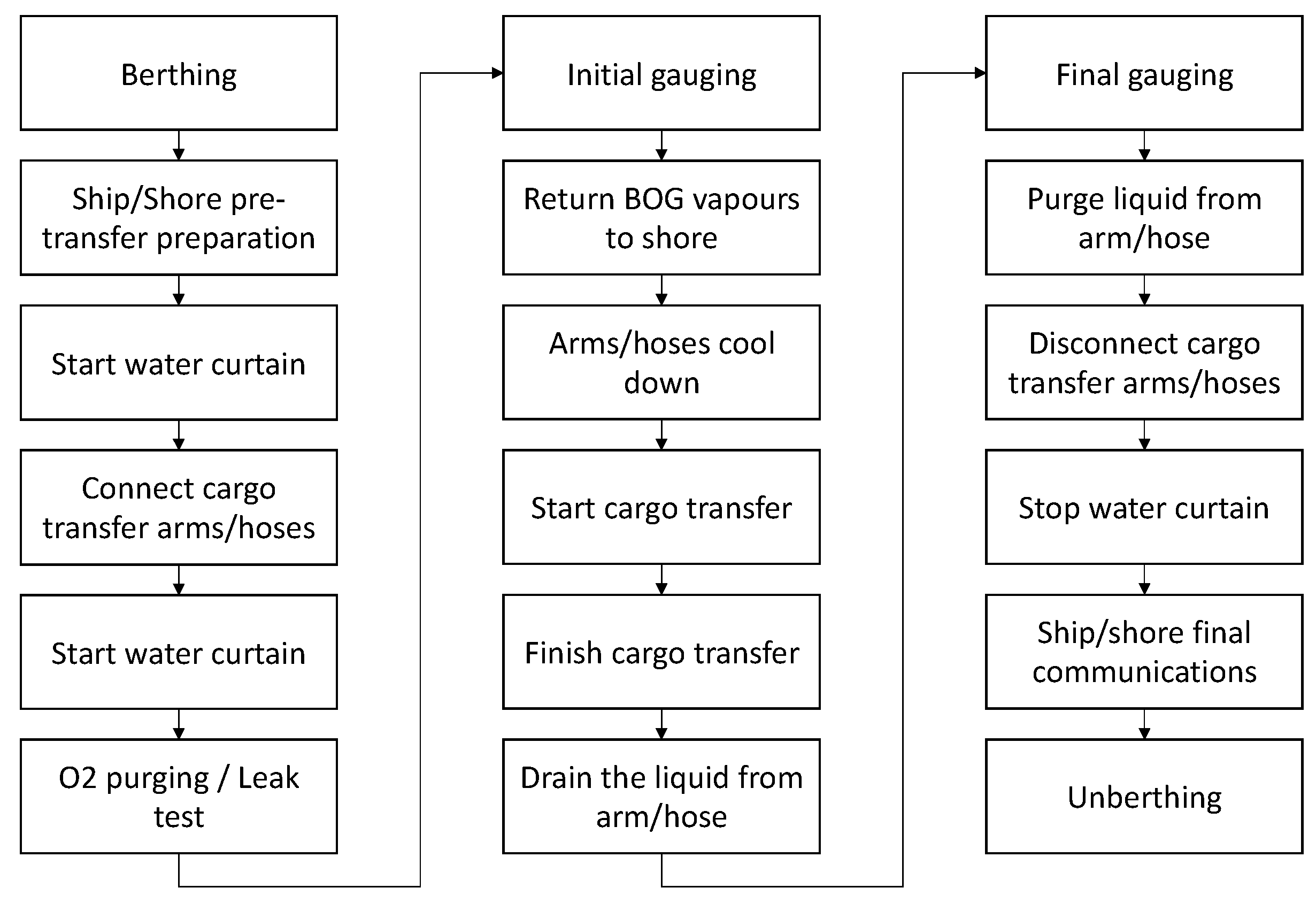
In terms of information exchange, immediately after the departure of the LNG vessel from the port of origin to the FSRU, a document containing all relevant information about the quantity, quality, composition of the cargo, ship configuration and the conditions under which she operates must be sent to the FSRU operator. In addition, this notice must include any other request for the STS transfer, as well as any information affecting the LNG. A more detailed scope of the LNG discharging from the vessel to the FSRU is illustrated in
Figure 2.
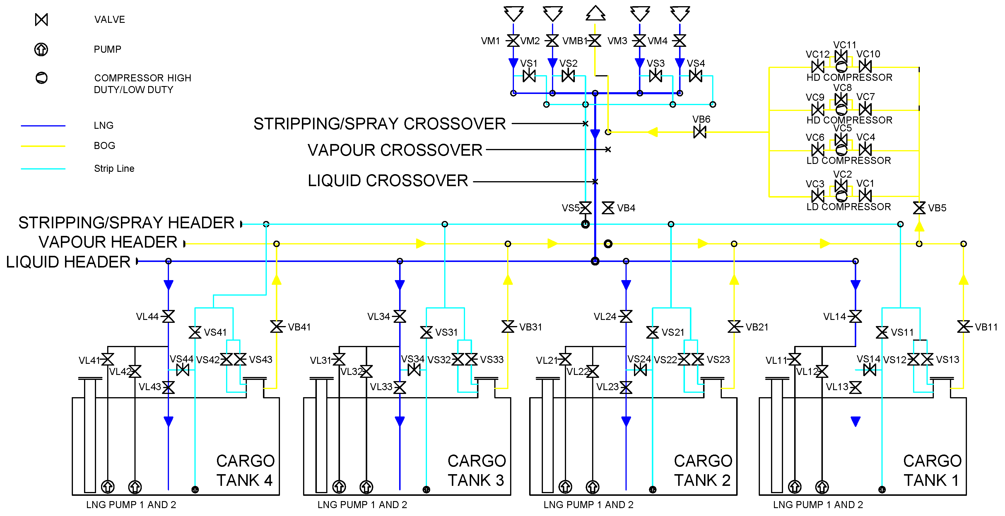
A schematic representation of the LNGC and the FSRU developed in AutoCAD is presented in
Appendix A, illustrating the main technical elements and parameters of the LNG transfer system. The schematic enables the distinction amongst several flows (LNG, BOG, etc.) and processes for the loading of FSRU and regasification of LNG is performed. The assumed layout and processes are the basis for the proposed simulation model.
Finally, some critical elements are controlled and monitored by the FSRU cargo control room constantly during operations. The most important elements are:
LNGC and FSRU cargo tank levels;
LNGC and FSRU cargo tank pressure;
FSRU pump load and discharging pressure;
Draft and trim of the LNGC.
Most of the aforementioned characteristics are incorporated in the proposed model described in the following section.
2.2. Description of the FSRU Simulation Model
The aim of the computational model was to simulate the operation of an FSRU in the context of tactical planning. With the loading and discharging parameters being known for the LNG vessel and the FSRU, the simulation model was able to calculate the time required to accomplish each process. In addition, the model produces results regarding the FSRU cargo tank level (or LNG inventory) and the send out rate of the natural gas from the FSRU to the gas network.
The simulation model consists of two basic subsystems, the LNG vessel and FSRU. The basis of the model is the cargo flows between the LNGC–FSRU subsystems. To encapsulate the flows in an accurate manner, specific input data parameters are required, namely technical characteristics for each LNG ship and the FSRU, as well as the estimated arrival time of each ship to the FSRU. The input parameters are presented in
Table 1. Storage capacity is used in connection with the tank level to simulate the LNG cargo inside each cargo tank of the LNGC and the FSRU. The commencement and ceasing of STS operations is triggered by those parameters. Other input parameters are the flow rate used to simulate the LNG flows from each cargo tank to the vaporizer unit. “NG send out rate” refers to the gas end out rate to the shore network.
The simulation tool was developed using MathWorks software tools, MATLAB and Simulink. Initially, a MATLAB code is used to request input for all the technical elements presented in
Table 1. This code makes the simulation modeling straightforward for the user, enabling them to insert data according to the specifications of the system under study. The features are not only able to meet the computational requirements, but also provide the user with a practical graphic interface of the Simulink processes. As a result, the user can produce a more intricate model for the FSRU operation by expanding the systems included in the initial model. Apart from the items in the Simulink library, developers can create their own functional blocks, either by designing them in Simulink or by coding them using the MATLAB platform.
The basic principle of the model is the proper representation of LNG flows during the STS and FSRU operation. To achieve this, Simulink signals and blocks are used to model the LNGC and FSRU pipelines, pumps and valves. The underlying principle of the block arrangement is the mass balance principle. The planning horizon is 2.5 × 10
6 s (or approximately 29 days), which is considered as a sufficient time period to simulate the operation of an FSRU and draw reasonable conclusions in terms of tactical planning [
11]. The tool has the capacity to simulate multiple consecutive discharges, limited only by the time horizon.
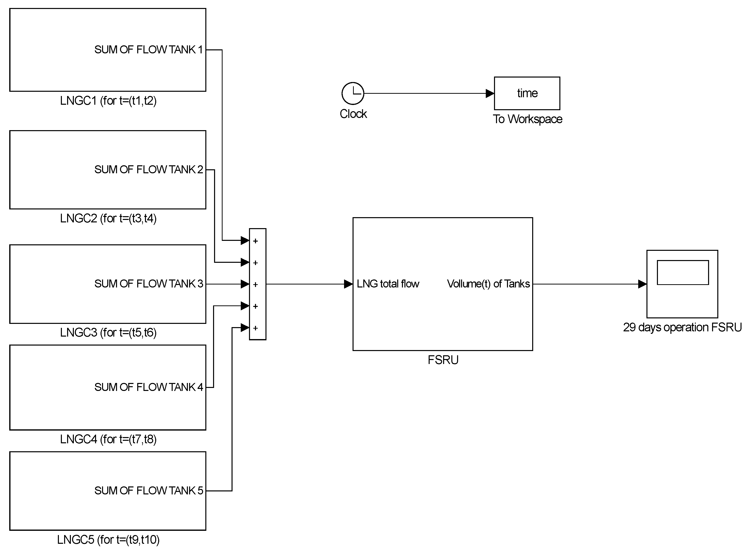
Figure 3 shows a conceptual representation of the model with an indicative number of five (5) LNG ships and the FSRU unit.
The general principle of the simulation is the calculation of the LNG flows during an STS transfer, according to the formula:
where
V is the volume of LNG as a function of time, and
Q is the flow of LNG.
To ensure a realistic simulation approach, each LNG ship is further analyzed as a unique subsystem, shown in
Figure 4. A block is assigned to each of the cargo tanks (i = 1,…,n), which sets a signal for the maximum value of the pump flow. By selecting each block, the user can enter a parameter that remains constant over time (“constant value”). Then, the signal enters the “use-valve over time” block in which the flow is represented as a function of time. The time sequence is completed by multiplying the flow signal by a new time-signal that the user creates based on the chosen scenario. The blocks “time” and “% of usage” are an f(t) signal function that takes the form the user decides by inserting two variables (time and %).
First, the subsystem “use of valve i over time” was used to formulate the signal as a function of time. The actual LNG flow is continuous and has been set as a function of time. Its signal will pass through the switch blocks. The role of the “anti-turbulence switch” and “full tank switch” is to reduce the pump flow for safety and functional reasons, when the LNGC cargo tank reaches a certain limit. In every case, the user sets the percentage by which the LNG flow will be reduced to. In the current research, the LNG flow decrease is represented by the 0.3 (or 30%) gain value. Furthermore, the switches are intended to stop the flow completely, when the LNGC tank has reached its preset limit. The two switches have an input which is the volume of LNG that has passed from the pump. Volume is calculated by integrating the flow of LNG over time, via the use of a pair of “integrator” blocks for each cargo tank. It is observed that when the full tank switch commutes between positions, the gas flow changes steeply without affecting the simulation result, because the valve placement is rapid in comparison with the time horizon of the simulation. Each switch block has three input, one threshold, and one output values. The two inputs are the signals which the block will process and select one as the output, while the third input is the reference value that the block uses to make the decision. The threshold is selected by the user for each LNGC and the FSRU. In the end, the signals from the four tanks are combined to create the overall flow to simulate the unloading of each LNGC in its entirety.
The modeling of the FSRU subsystem, as displayed in
Figure 5, enables the simulation of the loading process and the subsequent LNG vaporization over time. The blocks for the FSRU cargo tanks are built in a similar fashion to the LNGC blocks. Indicatively, there are four tanks in the selected FSRU, as this is the usual case, and each one of them has its own block series.
The LNG flow from the LNGC to the FSRU is represented as a separate subsystem. The signal of the FSRU cargo tanks is processed to ensure that when a tank is filled up to its given limit, the LNG flow is directed to the next empty tank. With the loading rate known (LNG rate from LNGC to FSRU), the flow signal is an input for the FSRU tank valve component, which simulates the flows according to a user-defined function. The simulation time for the FSRU is not limited to the discharging process of one LNGC, but includes all the operations taking place during the time horizon of the tool (29 days).
FSRU loading must satisfy the mass balance principle and is assumed to comply with the respective rules and regulations to ensure its stability and safe operation. According to the mass balance principle the total mass accumulation in a system without buffer must be equal to zero. In order to satisfy the principle in the system, a feedback signal is added, which will re-introduce the excess LNG resulting from the valve block to the system, when a tank fills up. The Simulink component performing the above procedure is shown in
Figure 5.
The signal of the FSRU tank subsystem accounts for the LNG flow into the tank and the outflow of gas (vaporized LNG) sent out over time. The technical characteristics for the vaporizer are set by the user and its flow time sequence generates the LNG flow rate heading for gasification. By comparing the total volume within the tank, to the tank filling limits the model which computes the LNG flow into the tank over time. The LNG flow is then converted to a volume signal, which is directed through a switch comparing the volume with the filling limit of the tank to avoid exceeding it. It is worth noting that the LNG balance within the FSRU can be negative, in case there is only LNG outflow for gasification without an LNGC discharging.
In
Section 3, the validity of the proposed simulation model is checked through different structured scenarios for the operation of an FSRU. The simulation assumes basic technical characteristics for the LNGC and FSRU. In addition to validation, the case study results will be used to discuss implication in management issues regarding FSRU terminal operations.


