Article

Tracking Tagged Inventory in Unstructured Environments through Probabilistic Dependency Graphs

Department of Mechanical Engineering, Carnegie Mellon University, Pittsburgh, PA 15213, USA
*
Author to whom correspondence should be addressed.
Logistics 2019, 3(4), 21; https://doi.org/10.3390/logistics3040021
Submission received: 8 August 2019 / Revised: 18 September 2019 / Accepted: 18 September 2019 / Published: 20 September 2019

Abstract

:
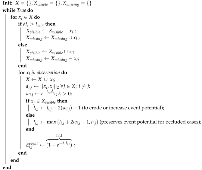
Logging and tracking raw materials, workpieces and engineered products for seamless and quick pulls is a complex task in the construction and shipbuilding industries due to lack of structured storage solutions. Additional uncertainty is introduced if workpieces are stacked and moved by multiple stakeholders without maintaining an active and up-to-date log of such movements. While there are frameworks proposed to improve workpiece pull times using a variety of tracking modes based on deterministic approaches, there is little discussion of cases wherein direct observations are sparse due to occlusions from stacking and interferences. Our work addresses this problem by: logging visible part locations and timestamps, through a network of custom designed observation devices; and building a graph-based model to identify events that highlight part interactions and estimate stack formation to search for parts that are not directly observable. By augmenting the site workers and equipment with our wearable devices, we avoid adding additional cognitive effort for the workers. Native building blocks of the graph-based model were evaluated through simulations. Experiments were also conducted in an active shipyard to validate our proposed system.

1. Introduction

Tracking and logging workpieces within a warehouse or storage yard is critical for industrial production and construction. In industries where objects are limited to structured shapes, such as standardized packaging or large quantities of known shapes, structured storage spaces are built to maintain smooth flow of inventory through the workspace. However, it is not always possible to build inventory specific storage or maintain them through transition of inventory, due to a finite limit on storage space and need to maximize utilization of available space. This case is prevalent in shipbuilding and construction industries that deal with materials of diverse shapes and use open floor or unstructured environments for ad hoc storage [1,2]. Both raw materials and parts for assembly and construction (referred to as workpieces) are stored mostly on open floors, for immediate convenience, until they are needed. Workpieces that are stored in such manner are often moved or consolidated by multiple stakeholders to optimize space utilization. Throughout these displacements, workpiece position needs to be logged and updated to facilitate fast pulls by other stakeholders downstream in the project. Construction and shipbuilding industries mostly use traditional methods of manual workpiece tracking that do not effectively update workpiece position when a change has occurred [3]. This is primarily because:
  • Logging personnel are not always around to constantly observe and update workpiece positions and movements.
  • Movers that interact with the workpieces are not always able to log or communicate interactions to required personnel or databases at all times.
  • A line-of-sight or direct observation is not guaranteed at every point to log and update positions due to occlusions.
A study of issues and reasons for poor pull rates in such industries by Grau et al. [4] discusses the cause of above issues in detail. In such cases, workers could spend up to 20% of their time searching, reordering or remaking workpieces when they cannot be found within a time period. Further, studies conducted by the authors of [2,3,5,6] in the construction industries show that 15–20% of inventory is lost in every project due to lack of organized storage and retrieval methods. Several methods to automate open-floor logging in construction industries are suggested in [1,7] using a combination of radio-frequency identification (RFID), geographical information system (GIS), global positioning system (GPS), ultrasound and barcode information. However, there are several issues in existing technologies that requires a sensor tag to be attached workpieces:
  • There is a cost of time and money to attaching sensor tags to every workpiece.
  • Sensors are susceptible to being damaged as heavy workpieces are stacked and are under tremendous force most of the time.
  • Heavy metallic workpieces and machinery can interfere and disrupt signals transmitted from these sensor tags.
Apart from singular use for the mode of data from RFID/GPS based tracking, current methods of inventory tracking are either primarily deterministic or propose probabilistic approaches to improve localization of observed signals [8]. These methods focus on reducing localization uncertainty for each workpiece using RF signals but do not predict or model where a workpiece might have moved to when no signal is available. If the workpiece is not available in its last known position, then there is no further information furnished by these systems to locate or help search for the workpiece. A system that can propose possible locations for a missing workpiece could reduce the search time that stems from lack of complete information. Since workpieces getting stacked and moved around by a variety of stakeholders is the primary cause of occlusions and missing parts, our work attempts to identify and track the outcome of such events. This allows us to propose a totem pole of search locations as locations of other workpieces with which they might be stacked along with. The alternative, given no further knowledge, would be to search in all possible locations with equal probability, which would cost a significant amount of time and effort due to the expanse of the workspace and search area. Our proposed system has the following contributions:
  • Observes and logs location and timestamps of workpieces from images through a network of observers;
  • Identifies, weighs and logs possible interaction of a workpiece with other workpieces into a graph; and
  • Identifies dependencies between workpieces, through a graph, that could have stemmed from events to propose search locations for missing workpieces.
The rest of this paper is structured as follows. Section 2 gives an overview of current popular methods used for inventory tracking in unstructured environments and methods similar to our own that is used in other applications. Section 3 details all the modules involved in our proposed system. Section 4 gives a detailed description of the working of our proposed graph-based model to track and locate workpieces. Section 5 describes the experiments conducted to qualify our proposed approach. Finally, limits and future work for our system are discussed in the Conclusions.

2. Related Work

The problem, which stems from lack of information and multiple stakeholder actions, of tracking and finding missing inventory in unstructured environments that our proposed work addresses is well documented [1,2,3,4,5]. Crowd-sourcing information through wearable technology to bridge such gaps in information in an industrial setting was discussed by the authors of [9,10]. With recent advances in the field of computer vision, image-based modes of information collection allow for richer context along while being more economical and less invasive [11]. The authors of [12,13] highlighted the possibilities of vision-based tracking for personnel safety and inventory tagging in unstructured and cluttered environments such as a construction site, making a case for such technology. As a mode of detection, potential of augmented-reality (AR) markers, in industrial applications for information collection and assembly instruction is an active area of interest. A prototype suggested by Salonen et al. [14] uses AR markers to locate workpieces and communicate action directives for assembly tasks. Work by Aleksy et al. [15] discusses frameworks to use AR markers to locate critical equipment and facilitate remote collaboration between field workers and experts. While use of AR markers to tag workpieces is an active area of interest for information collection and AR-based assisted actions to perform tasks efficiently, there is little work that deals with the problem of occluded or missing workpieces and assistance to search for them.
To make predictions or model what might have happened to a workpiece that is missing, high-level human reasoning needs to be employed over available deterministic data. This area of our work (Section 4.2), where we model such reasoning, is similar to those recently used in the field of computer vision to reason over observed detections [16] for applications such as object tracking and understanding scenes [17,18]. These methods attempt discover the underlying reasoning as cause and effect, to model the behavior of identified subjects in a continuous video stream. While these reasoning-based methods work in continuous video streams where behaviors are closely knit, a workspace in an industrial setting provides more disjoint and sparse data. Given the sparseness of observations, our approach is top-down wherein high-level knowledge is built into our model based on common human knowledge of what could lead to missing workpieces. The model is then evaluated to justify the built cause and effect relation. We further employ a probabilistic approach to build relations between workpieces to maintain ambiguity as true relations are not directly observable. While our proposed work borrows from a variety of research streams discussed above, to our knowledge, there is not much work in literature focused on facilitating the search of missing workpieces in unstructured environments. This forms the core contribution and focus of our proposed system.

3. System Architecture

The objective of our system is to locate and estimate locations of workpiece from observations made by a network of movers throughout the workspace. Our system contains three high-level modules (Figure 1) that represent the tasks of observation, detection and inference. The entire system is built on a Robot Operating System (ROS) platform [19] to implement the modular design. Each mover serves as an observer node in ROS that publishes images along with timestamps, as a topic. The detection module subscribes to these topics and extracts relevant information through AR markers such as unique identification (ID), location with respect to camera, and then publishes this information on observed workpieces as topics. The inference module subscribes to the topic published by the detection modules and identifies events and estimates location of observed workpieces. Under this framework, cameras used for security and monitoring of the workspace can also be leveraged as observers for the observation module.
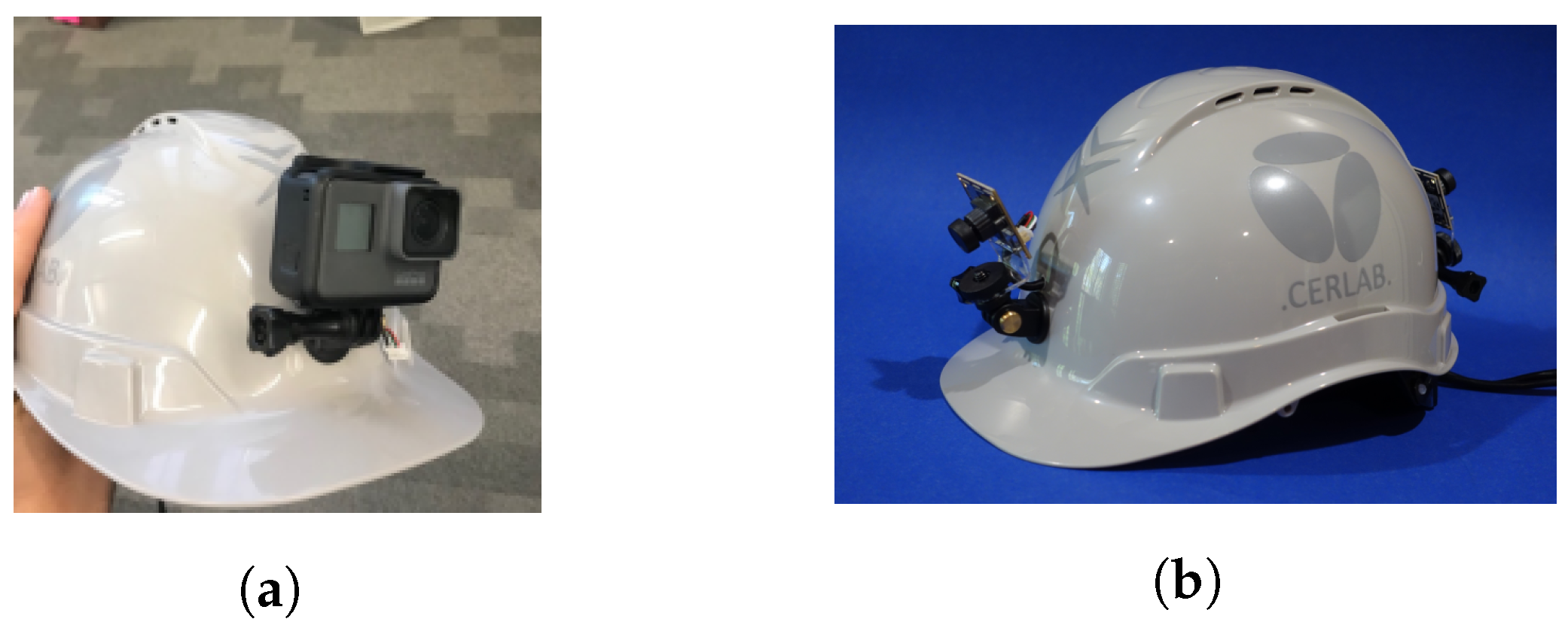
Observation module: In our system, we use wired usb-cameras and wireless GoPros to capture and transfer images to Raspberry Pis attached to the helmets of workers (Figure 2) and machinery such as forklifts, collectively referred to as movers, to move and interact with workpieces. As multiple movers move around the workspace to interact and move workpieces, this module publishes images from their view at 30 frames per second (fps). These images represent the raw data from which workpieces tagged with AR markers and events are identified by the detection and inference modules respectively. Figure 1 shows the outline of our system.
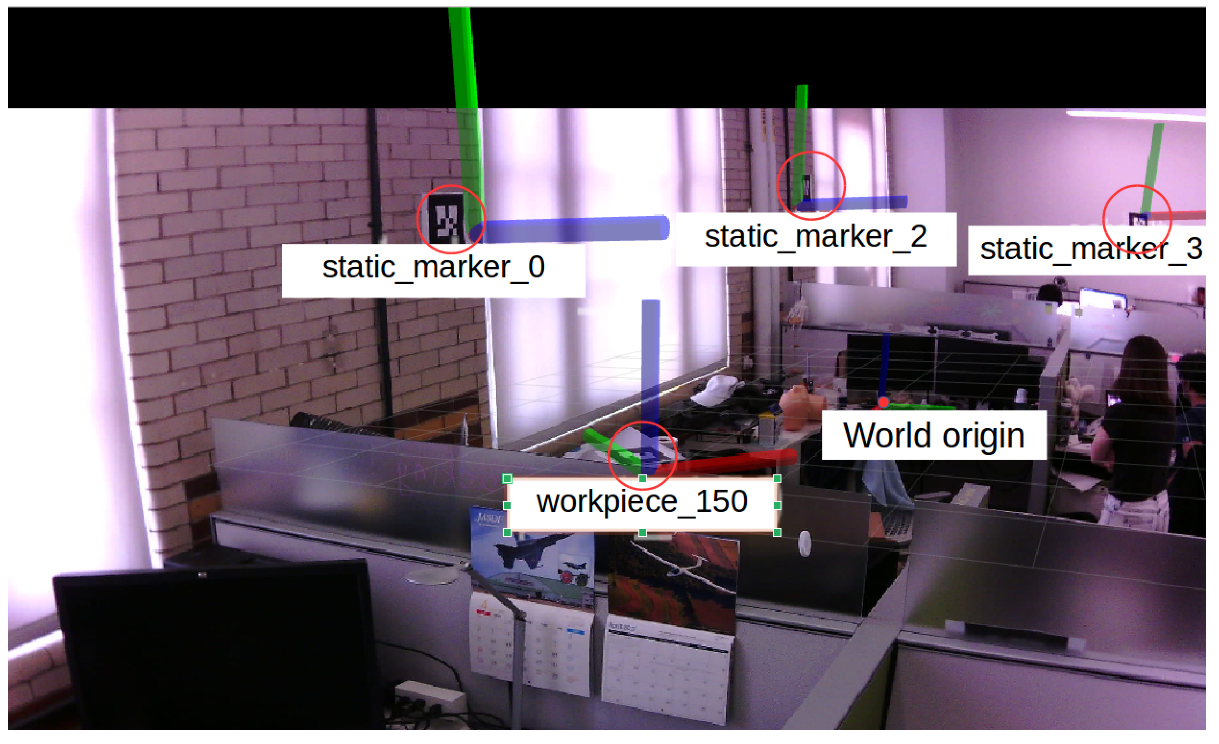
Detection module: This module processes images received from observers to identify objects of interest and their pose (3D cartesian). In our system, we detect AR markers attached to workpieces using open-source Alvar library, available as a package in ROS [20]. AR markers attached to the environment serve as static markers to position the camera co-ordinate frame of the mover with respect to the workspace or world co-ordinate frame. Similarly, AR Markers attached to the workpieces enable us to position workpieces with respect to movers (Figure 3). In our setup, static markers are three times as large as the workpiece markers since static markers are observed from afar while workpieces are observed at much closer proximity. The larger size of the static marker allows for recognition and localization from larger distances. Marker size and placement are design decisions driven by factors such as required accuracy, range of detection, environment lighting and camera parameters. Work by the authors of [21,22,23] provides an analysis on accuracy, precision and behavior under occlusions and lighting conditions of various AR marker detection toolboxes.
While lighting conditions, camera and subject movement, and camera field of view affect the ability of this module to extract deterministic observations of workpieces, our work presented here is not focused on improving direct identification of the workpieces with attached AR markers. Our work focuses on predicting events that could have occurred and tracking the effects of such events based on available detections of the workpieces. The AR marker detection tool can be replaced with any other detection package that can extract the position and ID of the workpiece and is not the focus of our current proposed method.
Inference module: This module estimates workpiece positions beyond deterministic information logged from direct observations of workpieces. In the case a workpiece was not recently observed (later than 2.0 s for our system), this module identifies events that could have caused its disappearance and tracks the effect of such events. This produces a totem pole of locations to search for that workpiece if it could not be found in its last reported position. Our procedure to build such hypotheses and estimate workpiece locations is described in detail in the next section. In most cases, workpieces are not constantly observed as there are no movers nearby, so the system identifies that position as a last-seen position. The core contribution of our work is in identifying events wherein the workpiece could have been stacked and tracking all possible future movements of the workpiece thereon. Our graph-based model to identify and track the effect of events to provide search locations for a missing workpiece is described in detail in Section 4.

4. Identifying Events and Building Location Estimates Using Graphs

Once workpiece observations are made, the inference module identifies possible events and tracks possible future positions of workpieces based on those events. For our work, any of the following can be considered as an event:
  • The stacking of one workpiece on top of another
  • Movement of the stack from one location onto another stack
  • Splitting of a stack into multiple stacks and moving them to other locations and stacks
The inference algorithm is modeled after simple reasoning employed when a human monitors inventory through a camera. If the workpiece is directly visible within the camera’s view, then we look no further since we exactly know where it is. However, if a workpiece is missing from its last seen location, then one would tend to go through the video feed and:
  • Go through all movers/workpieces that were observed within the vicinity of its last known position.
  • Rank or weigh the list of movers that could have taken the workpiece based on the duration and proximity of interaction or lingering. The longer is the duration and closer is the proximity, more likely it is that they interacted with the workpiece.
  • Follow the suspect list of movers thereon and identify a list of locations at which the workpiece could have been dropped off.
In our system, since the movers are assumed to have cameras attached and act as passive observers (Figure 2), we only monitor events and interaction between workpieces. The above process then focuses on visible workpieces as possible suspects for search locations for a lost workpiece based on identified events.
The intuition described above is also our motivation to build a graph-based model to identify and track events in a probabilistic manner. Factors such as proximity and temporal data can be used to estimate the strength or confidence of events between any two objects. These form simple building blocks but translating the effect of such events when there are multiple interactions between multiple workpieces is difficult to track. Graphs have been successfully used to model such systems. Simple building blocks can be used to establish relations, as edges, between any two workpieces, represented as nodes. These simple relations are then used to build more complex relations or dependencies between all the workpieces to track the effects through paths, reachability and connectivity between nodes within the graph-based model.
Section 4.1 discusses our approach to identify events and dependencies using graphs. Section 4.2 demonstrates the various native mechanisms in our graph model with scripted scenes in a simulated environment.

4.1. Building Graph of Events between Workpieces

The event graph models the probability of an event occurring between any two workpieces for all available workpieces observed within the system. All observed workpieces X = { x 0 , x 1 , x n } ( x i R 3 ) are represented as nodes and the probability of an event P ( E v e n t i , j ) between any two nodes x i , x j is represented as edge E i , j in the undirected graph G e v e n t (Figures 5–11). Since an event in this system is described as an interaction, its probability of occurrence is dependent on two factors; proximity between the two workpieces and duration of time the workpieces were within and out of each other’s proximity. This and can be formulated as Equation (1).
E i , j t = h ( x i , x j , t , θ )
such that h ( ) increases if x i and x j are within each other’s neighborhood and at least one of x i and x j is visible and decreases if x i and x j are out of each other’s neighborhood and both x i and x j are visible. Since the edge strength is representative of the probability of an event between x i and x j , we have 0 < E i , j 1.0 .
where,
θ R N is the function parameter for h(.)
t : represents time
E i , j t : is the edge weight between x i and x j at time t in the graph G e v e n t .
The requirements above are such that we want the edge weight E i , j between the two nodes x i and x j to increase with time when any two workpieces are observed close to each other as they are more likely to get stacked. At the same time, we want E i , j to decrease when we observe both x i and x j far from each other as there is diminished chance of them getting stacked or interact with each other. Apart from proximity, time spent in proximity is also factored into E i , j as there is time cost involved when workpieces are getting stacked. Without accounting for time spent in proximity, situations where workpieces are momentarily passing by, physically close to each other, will tend to trigger events which in turn increases the search space. While there are a variety of ways to encode these behaviors in h ( ) , our approach here is to model h ( ) as a cumulative distribution function over an exponential distribution, as described in Algorithm 1.
Algorithm 1: Building event graph G e v e n t .
Logistics 03 00021 i001
where,
δ t i Elapsed time since last observation for workpiece i
t m i n User defined time threshold to set the state of a workpiece as missing. This is set to two seconds in our experiments.
λ d Rate parameter for an exponential distribution to decide weight decay within a workpiece’s neighborhood (user set parameter). Smaller values of λ d has wider neighborhoods with softer weights translating to slower rate of increase in the linger counter within the neighborhood. Higher values have smaller neighborhoods with sharp weights within, translating to sharp increase in linger counter when workpieces are within the tight neighborhood. λ d > 0
w i , j Weight attributed to proximity factor modeled as an exponential decay for lower values at larger distances between workpieces
l i , j Linger counter to increase or erode potential for an event with time. Longer a workpiece is observed within proximity (lingers), higher the value. Range is clipped as 0 < l i j < l m a x to keep the value bounded.
λ l Rate parameter to convert cumulated linger values l i , j to a probabilistic estimate through an exponential cumulative distribution function. Smaller values for λ l translates slower rate of increase in event potential whereas a higher value produces a higher rate of increase. The values are determined by the user depending on the workpiece movement character. Note that rate at which the event potential reaches 1.0 can be controlled with both l m a x and λ l
After an event, a workpiece x i can be in any of the following states:
  • Present and visible;
  • Present but occluded in its last seen position; or
  • Moved to another position but still occluded due to event(s).
In all the above cases, we observe the following:
  • We lose line-of-sight for all workpieces that get stacked upon.
  • The workpiece on top of the stack is the only workpiece that can be directly observed and tracked.
  • A stack might get dispersed, shuffled or split into other stacks while not having a line-of-sight for all its members.
In all the above cases, there exists a dependency between the occluded workpiece and other workpieces forming a stack. Since stacks can cumulate and be dispersed, shuffled or split without direct observation of the process, we preserve chained dependencies between the members involved. These dependencies are tracked by the dependency graph G d e p e n d e n c y .
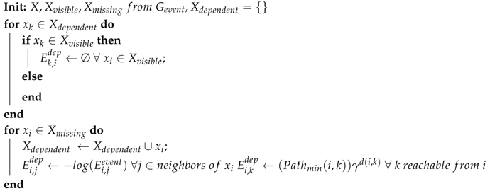
Once the events are identified and logged into the graph G e v e n t , built as per Algorithm 1, dependencies between workpieces are extracted from it as G d e p e n d e n c y . The nodes in this graph represent the workpieces, whereas the edges represent the strength or probability of dependence between the nodes. An edge in this case directly represents the system’s belief that the involved nodes are in a stack. Using this graph, for any given workpiece, we can get a list of other workpiece locations it might be stacked at. While G e v e n t builds events for all observed workpieces in both X v i s i b l e and X m i s s i n g sets X , G d e p e n d e n c y is only updated for x i X m i s s i n g as a recently observed or visible workpiece is expected to be independent of other workpieces. G d e p e n d e n c y is built as described in Algorithm 2.
Since the edge weights are positive for G d e p e n d e n c y the shortest path also takes the path of highest edge probability or strength in G d e p e n d e n c y . In our system, we use Dijkstra’s algorithm [24] to calculate this path. The penalty factor γ in Algorithm 2 encodes the confidence for workpieces to be stacked with other workpieces through indirect events (described in Section 4.2).
Algorithm 2: Building dependency graph G d e p e n d e n c y .
Logistics 03 00021 i002
where,
P a t h m i n Shortest path (based on edge weights) between nodes i and k in G d e p e n d e n c y .
d ( i , k ) Distance in terms of node separation between i and k.
γ Penalty factor for separation.

4.2. Native Mechanisms in Our Graph Model

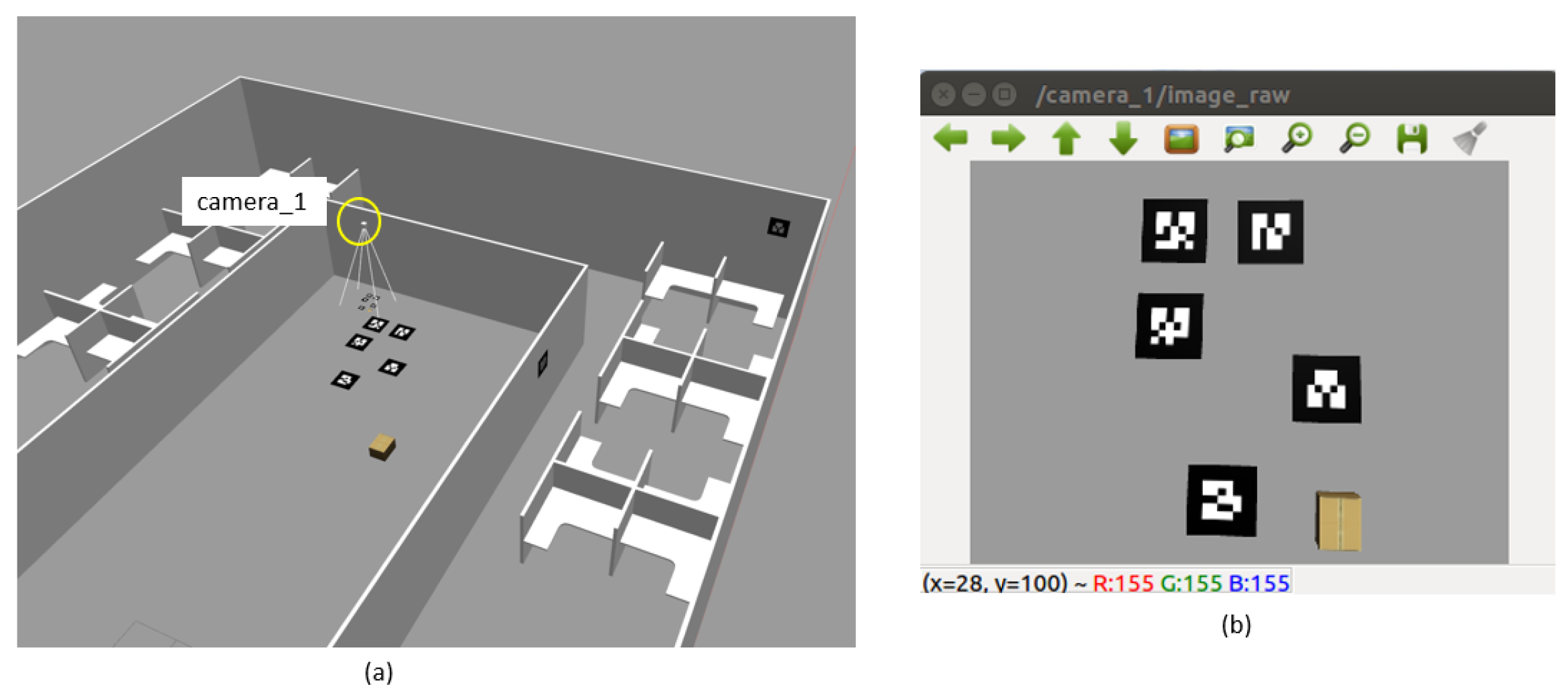
In this section, we demonstrate the native mechanisms in our graph structure that builds and updates events and dependencies between observed and missing workpieces. Our system was tested using observations made from a simulated virtual environment in Gazebo [25], as shown in Figure 4. This environment allows us to place and move the AR markers (placeholders for workpieces) and virtual cameras to simulate simple scenarios. Since the cameras were simulated with known intrinsic and extrinsic parameters, no additional calibration step was taken. The camera image shown in Figure 4b was re-rendered for clarity, as shown in Figure 5, Figure 6, Figure 7, Figure 8, Figure 9 and Figure 10.
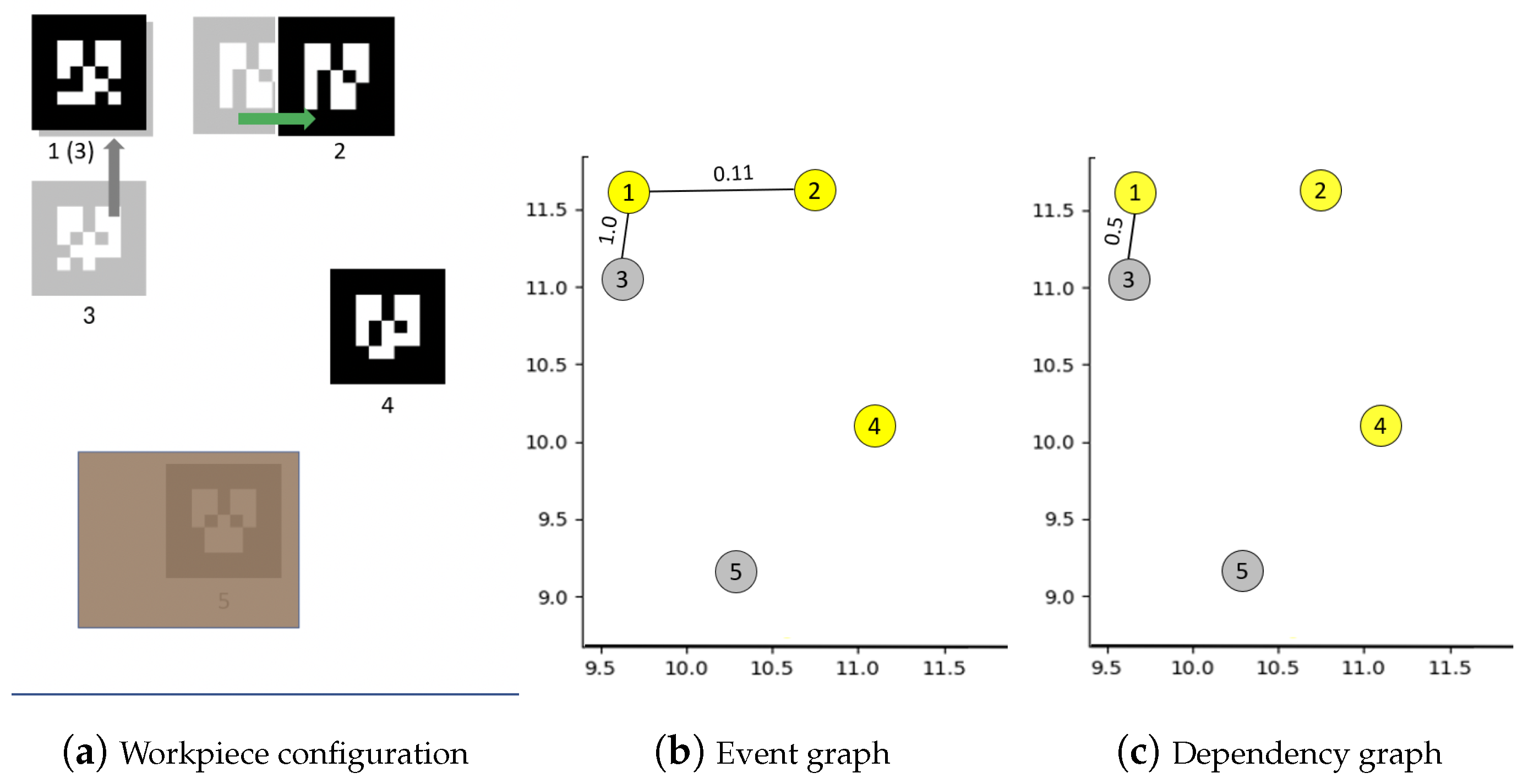
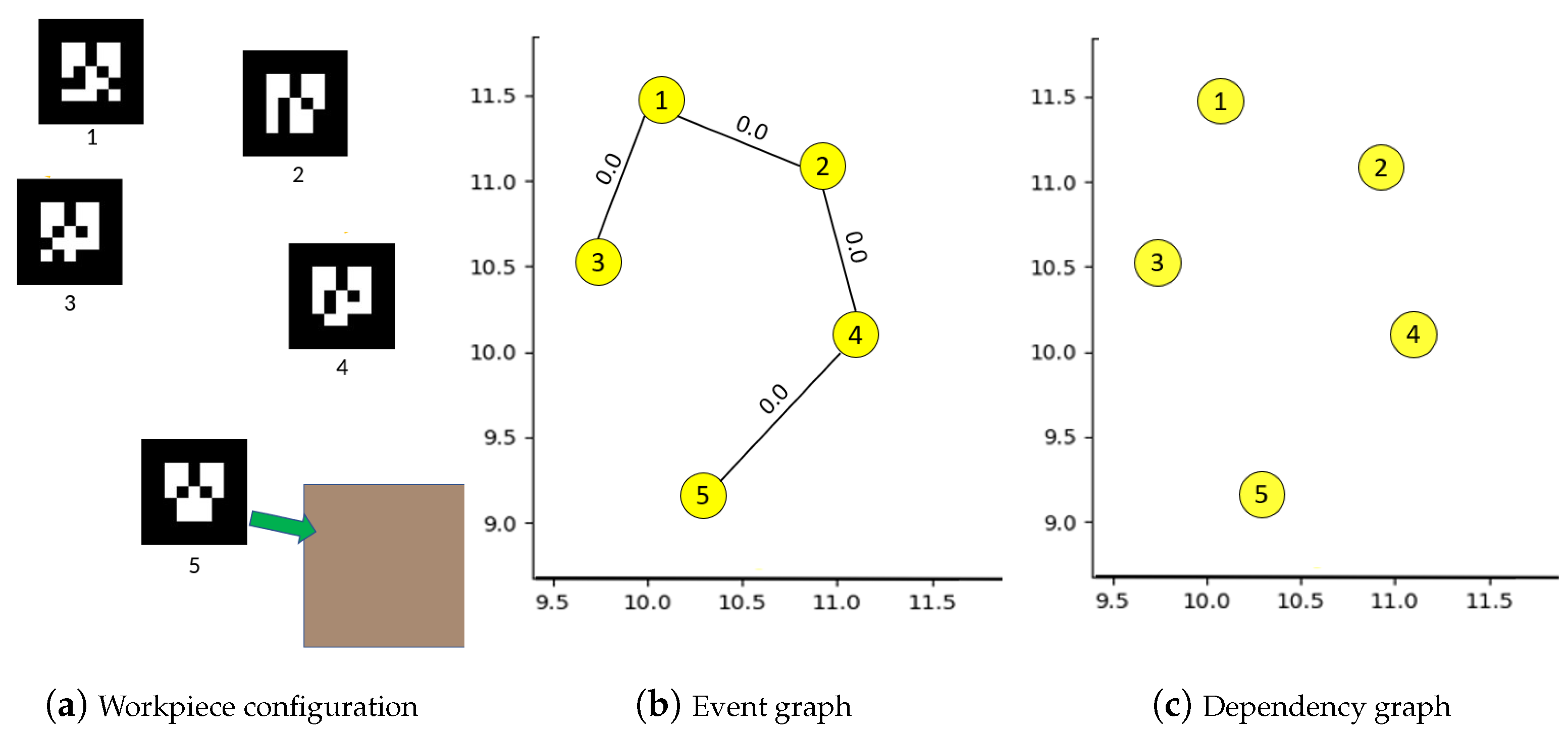
Populating and setting the state of workpieces as nodes: As soon as Workpieces 1–5, shown as AR tags, are identified within an observed image published by any of the cameras, its unique tag, location and timestamps are logged into the system (Figure 5). Since all the workpieces are directly visible, no dependencies are observed by the system’s dependency graph (Figure 5c).
Identifying events and building event weights: The distance and time spent within each other’s proximity is constantly observed and the edge strength for possibility of an event is updated at every observation. As shown in Figure 5b, edge weights E 1 , 3 e v e n t and E 1 , 2 e v e n t are increased as Workpieces 1 and 3 are within proximity of Workpiece 1’s neighborhood, increasing potential for an event. In addition, note that the dependency graph, at this point, has no edges among Workpieces 1–3 as all workpieces are still directly visible making them independent of each other. Edge weight for E 1 , 2 e v e n t is eroded as per Algorithm 1 when Workpiece 2 is observed away from Workpiece 1 (Figure 6b). This demonstrates the diminished confidence in potential for events when members are observed to be moving away from each other.
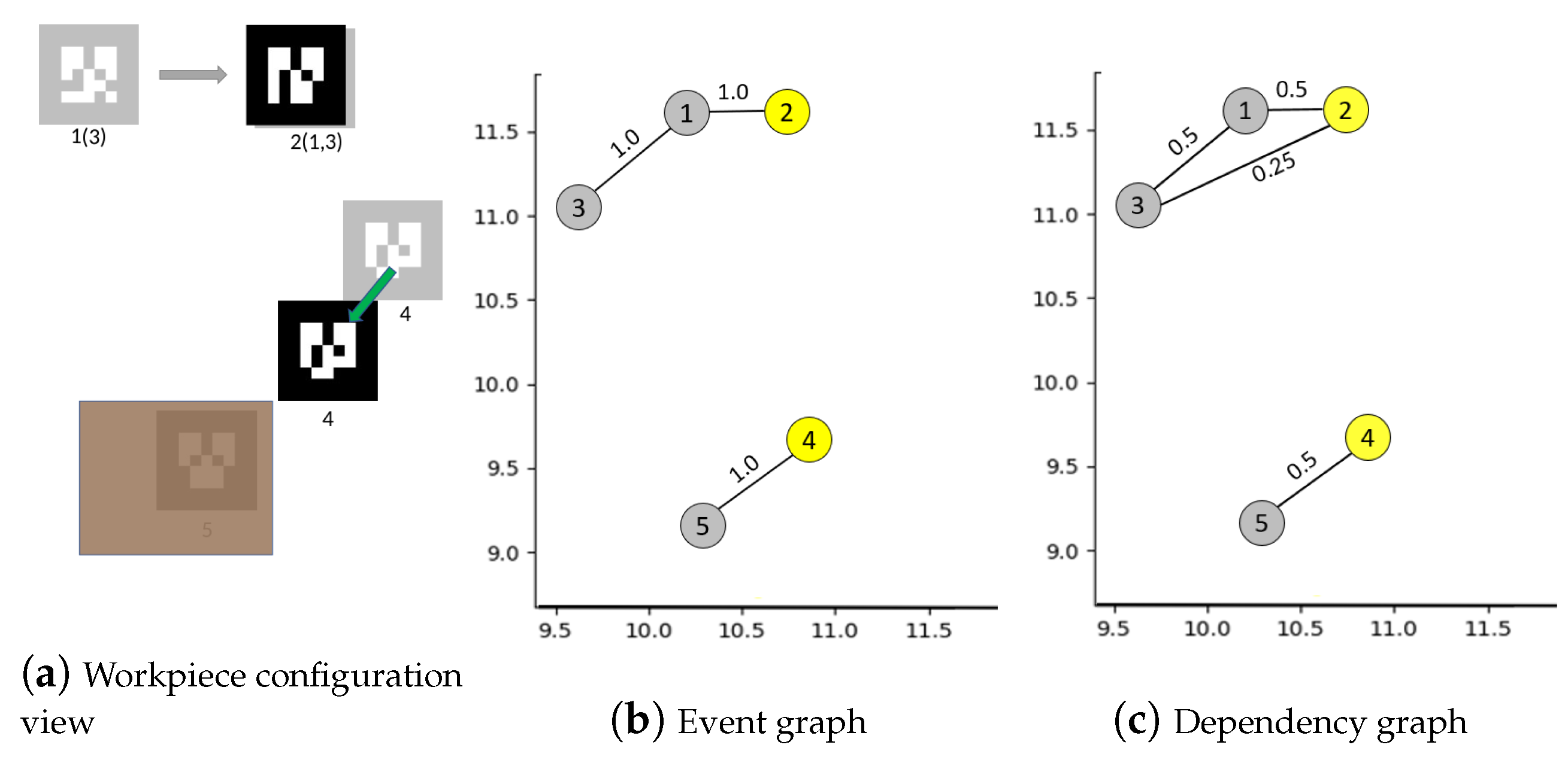
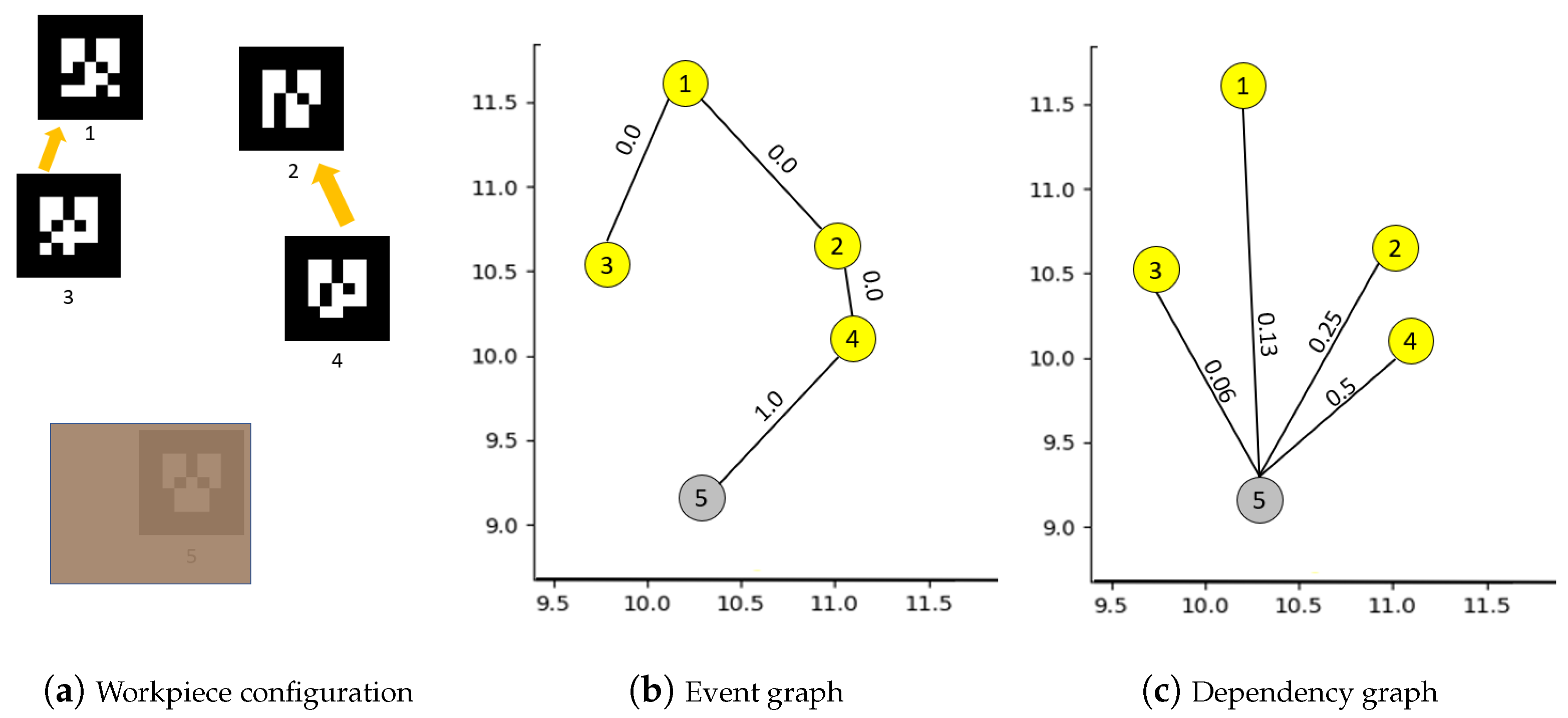
Dependency for missing or occluded workpieces: When a workpiece does go missing, due to lack of direct observations for a period of time, G d e p e n d e n c y looks up G e v e n t to identify potential events and builds relations between relevant members. In our case, since Workpiece 3 gets stacked under 1 (Figure 6a) and since we already identified potential for an event between Workpieces 3 and 1, a possible dependency between them is established in G d e p e n d e n c y . At the same time, we occlude Workpiece 5 with a random object (Figure 6a). Since no potential events involving Workpiece 5 were observed in G e v e n t , its state is set to missing or occluded with no dependencies (Figure 6b). However, if other workpieces, such as Workpiece 4, are observed within the neighborhood of its last known position (Figure 7), we still treat Workpiece 5 as being present in that position, but possibly occluded, and increase the potential for an event with Workpiece 4 (Figure 7b). This in turn creates a dependency between Workpieces 4 and 5 (Figure 7c).
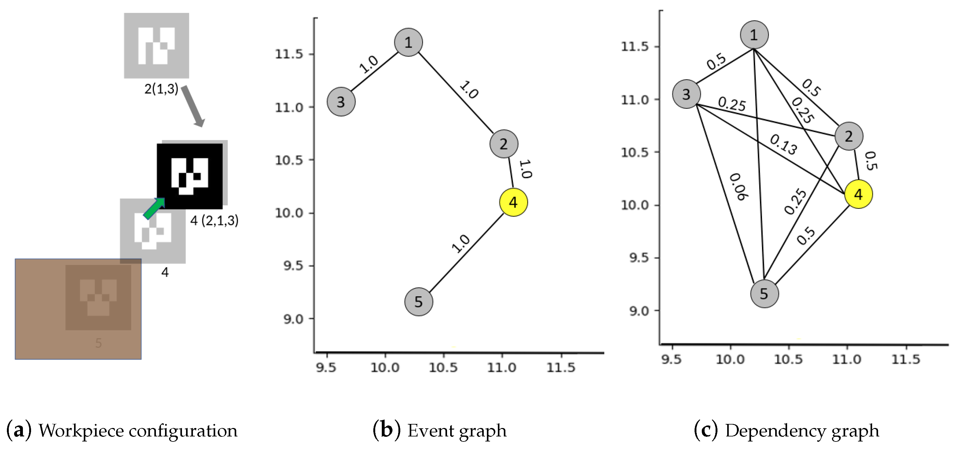
Direct and indirect dependencies: Stacks can further be stacked, shuffled and dispersed during inventory pulls. G d e p e n d e n c y tracks all such chained events to appropriately update dependencies. In Figure 7a, Workpiece 1 is moved and stacked with Workpiece 2 creating E 1 , 2 in G d e p e n d e n c y . However, since Workpiece 3 was already believed to be stacked with Workpiece 1, an indirect dependency between E 3 , 2 is also built in G d e p e n d e n c y (Figure 7c). Stacking Workpiece 2 with Workpiece 4 creates similar chained indirect dependencies E 1 , 4 E 1 , 5 E 3 , 4 E 3 , 5 E 2 , 5 in G d e p e n d e n c y (Figure 8). Note that the higher is the node separation between workpieces, the less confident the system is in that location due to a separation penalty of γ = 0.5 .
Breaking dependencies when a missing workpiece is observed: Once previously missing Workpiece 3, suspected to be in a stack with Workpieces 1, 5, and 2, is observed (Figure 9), all possibilities on how the stack might have split needs to be covered. In our case, let us say that the occluded members of the stack were shuffled somewhere along the way. When Workpiece 3 is observed, the stack is assumed to be split with no direct knowledge of the order of split so G d e p e n d e n c y preserves all possibilities of the split wherein missing Workpieces 1, 2, and 5 could be stacked under either of Workpiece 3 or 4. The same reasoning is repeated when later Workpieces 1 and 2 are also directly observable (Figure 10) after getting split from their respective stacks.
Note that, in Figure 10c, the system was not sure of the location of Workpiece 5 and believes that it could be under any one of Workpieces 1–4. While it may seem exhaustive to search under all other workpieces for Workpiece 5, the system does preserve the last known position in memory, making it the first location to search for based on generated totem pole (described in Figure 12). In the case Workpiece 5 was not found at its last known position as in Figure 10, based on occurred events, our system proposes the other workpieces that interacted with it as search locations. Once Workpiece 5 was observed again, all workpieces within this scene become independent of each other (Figure 11).
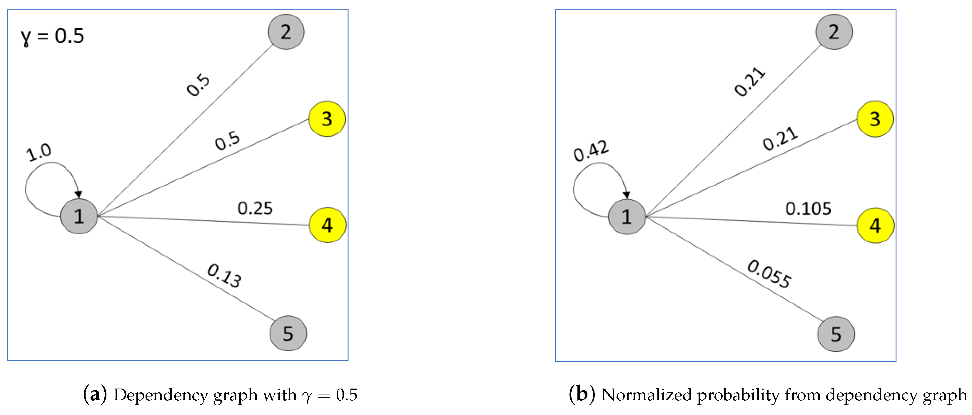
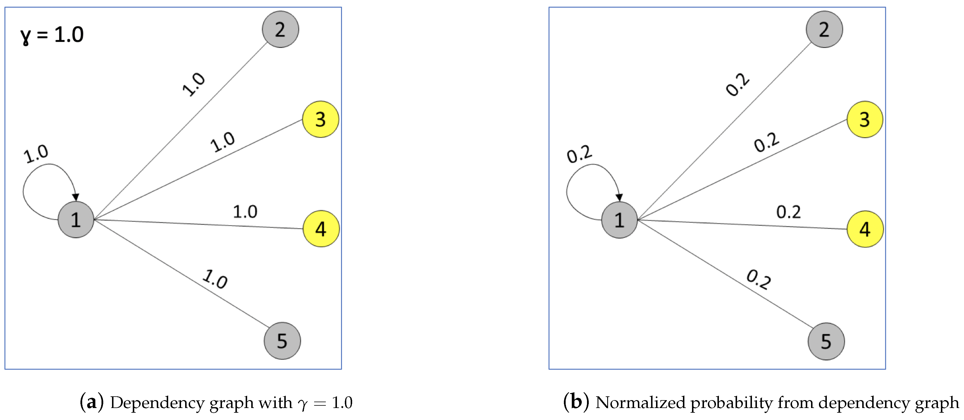
Getting a totem pole of search locations for a missing workpiece: Once G d e p e n d e n c y is available, a totem pole of possible stack locations can be generated for any workpiece x i in it. The resulting list is based on normalized weights on the edges of x i in G d e p e n d e n c y , as shown for Workpiece 1 in Figure 12 and Figure 13 for the frame in Figure 9. The value of separation penalty γ has a direct effect on the totem pole of search locations as it penalizes indirect events based on separation levels. With γ = 0.5 , the totem pole of locations (Figure 12) we get for Workpiece 1 is quite different with γ = 1.0 , reflecting no separation penalty, for the same state of events (Figure 13). The value of γ is determined by the user as per the environment. If it is commonplace for stacks to get further stacked and dispersed through the workspace, γ 1.0 would be preferred. However, if the chance of stacks getting further stacked is quite low, then γ < < 0.5 would be more appropriate. A lower γ value would reduce the significance of locations resulting from chained stacking in the totem pole. A value of γ = 0.0 would completely ignore all chances of stacking and would force the system to suggest the last seen position as the only search location.

5. Experiments and Results

Since we were not able to identify similar approaches to our own, we conducted experiments in our own simulated environment (Figure 14) and in a real-world shipyard environment to evaluate our system. In the simulated environment, we highlight the benefits of providing a totem pole of locations to search for against uninformed searches when a workpiece is missing. Since the goal of our system is to propose a search strategy, we count the number of locations to search for a missing workpiece, until found, as the metric of evaluation. The baseline used to compare our system performance is the uninformed strategy that has no prior information to guide the search. In current practice, if the workpiece is not directly visible, all other locations of stacked workpieces are equally likely locations to search. The expected number of locations to search for in this case can be modeled as the expected number of guesses needed to find the correct location, given equal probability of finding the workpiece in each location. This baseline is calculated as per Equation (2).
While the simulated experiment highlights the benefit of our system in reducing the expected number of search locations, we also show a proof of concept of the system in a real-world shipyard. Here, we conducted scripted experiments to qualify the ability of our system to identify events and build dependencies between workpieces. The objective of conducting the real-world experiments is to show that our system can be implemented under typical conditions of lighting and movement, to effectively extract otherwise hidden relations between workpieces through stacking.

5.1. Simulation Based Experiments

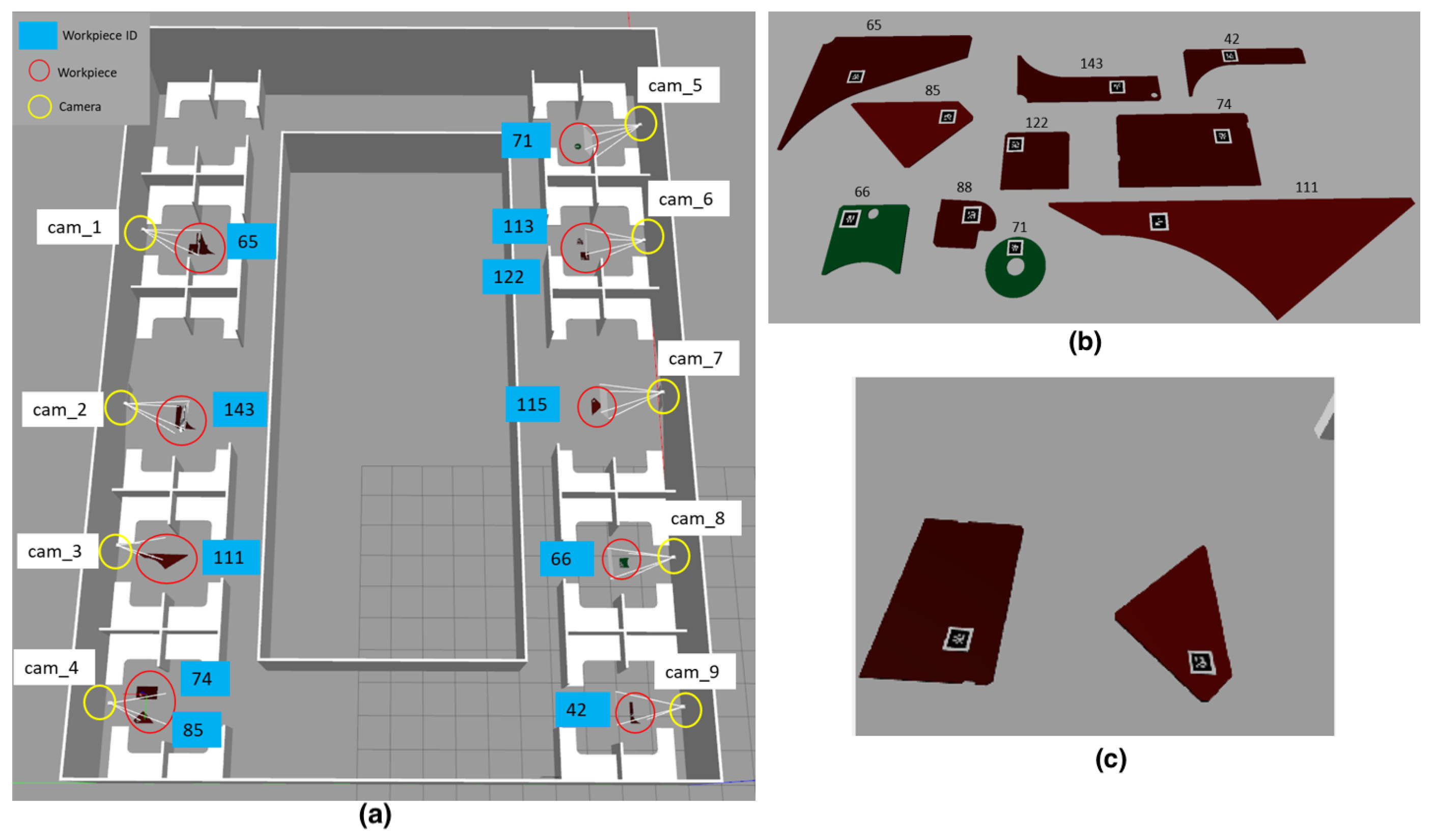
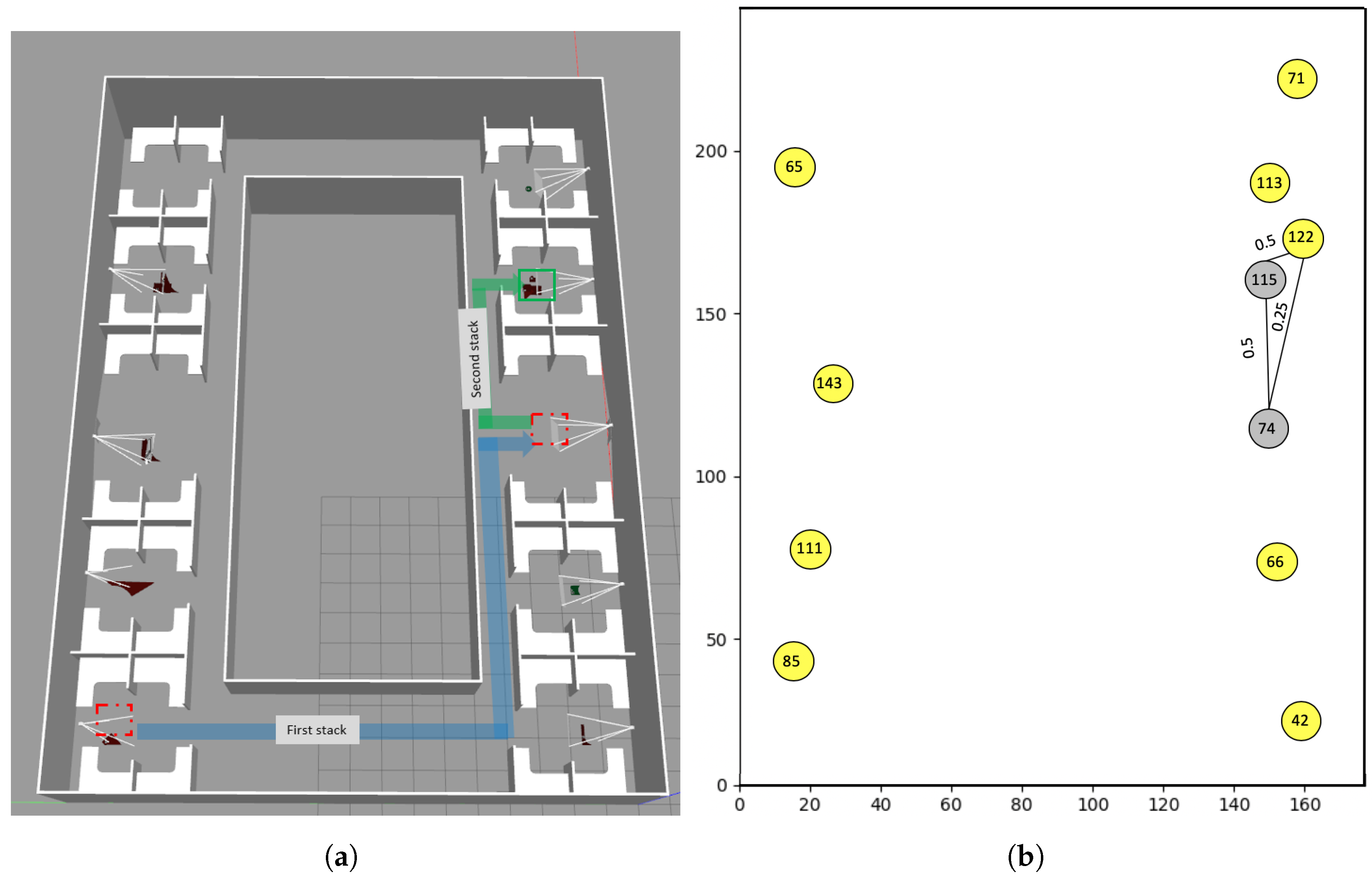
Our simulation environment reflects our office space built in Gazebo [25] with workpieces and fixed cameras at various locations (Figure 14). Since the cameras are fixed, their positions are known, thus static markers are not necessary to get their location. The scene is a simple representation of an environment where there are multiple stack and storage locations for workpieces. We simulated a simple stacking scene where Workpiece 74 is moved from its position and stacked under Workpiece 115 following the path shown in Figure 15a. Next, this stack with Workpieces 115 and 74 is further moved and stacked under Workpiece 122. The result of our system as G d e p e n d e n c y with the node locations encoding actual XY position of the workpieces is shown in Figure 15b. At the end of these two simple stack moves, we measure the result as the number locations to search for until the workpiece is found by a worker unaware of the movements of the workpiece with and without the result of our system. For a worker, when a workpiece is not present in its last seen position, the rest of the locations of other workpieces become possible search locations as there is no available log of interactions to further prune the search space. For such a case, in an environment holding N other workpieces, the expected number of guesses to find the right workpiece under which the missing workpiece might be, is given by Equation (2). This forms the baseline we use to compare the result of our system. The resulting search attempts are tabulated in Table 1 with varying total locations N to search in. The highlight of the result is that the number of locations, based on guessing, grows with more workpieces or storage locations introduced into the workspaces.
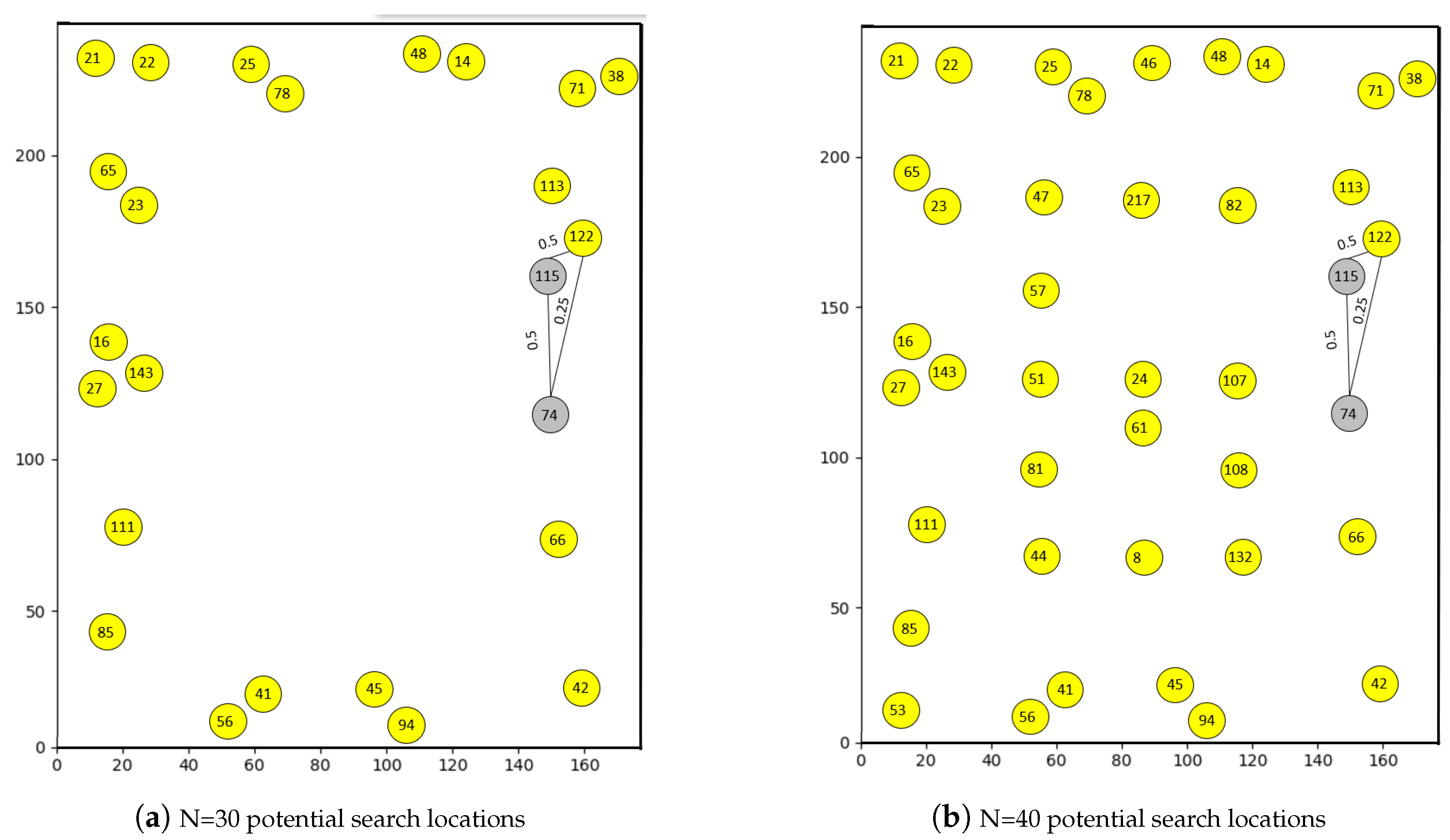
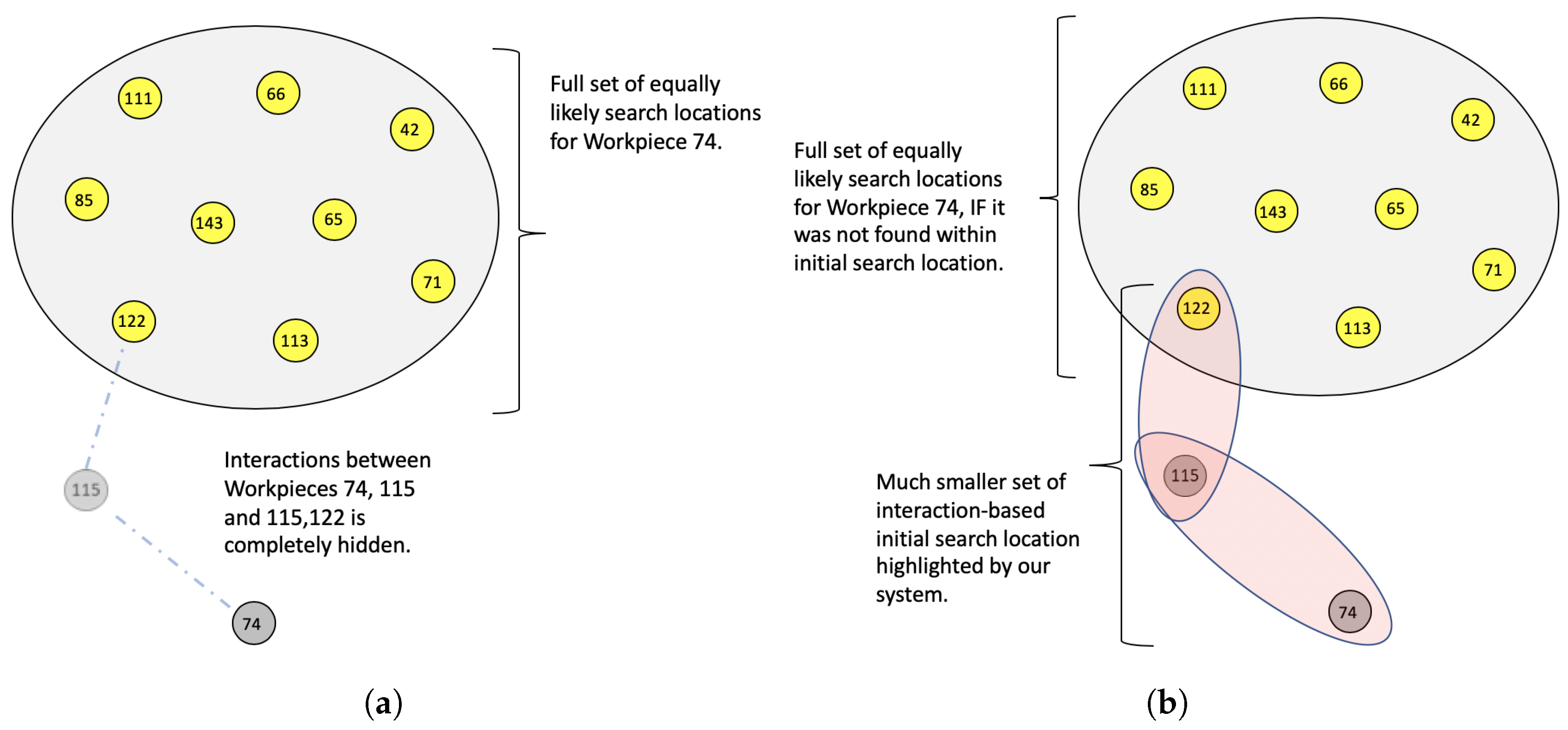
On the other hand, with our system, the search locations grow only based on the interactions that the missing workpiece might have encountered. The addition of workpieces in other areas in the workspace have little to no effect for the missing workpiece in our system as it inherently ignores the effect of workpieces with which no interaction could be possible. This is shown in Figure 16 where even as N grows within the workspace, the edges for Workpiece 74 is only dependent on the workpieces that it interacted with. While it is possible that there could be cases where an event went completely undetected due to recognition error, at worst, the totem pole suggested by our system is no worse than sampling a list of positions to search for from a set of uniform locations. The information that our system extracts and its effect to reduce the search space against that of an uninformed guess is visualized in Figure 17.
E ( X ) = x = 1 N ( x ( P s u c c e s s ( x t h t r i a l ) P f a i l u r e ( ( x 1 ) t r i a l s ) )
Equation (2) translates to ( N + 1 ) / 2 when all locations are equally likely. While Equation (2) is quite manageable for guesses for smaller numbers and smaller spaces, the benefits of having a totem pole become significant when the locations to search, N, gets larger as shown in Table 1.

5.2. Real World Experiments

While simulated experiments have clean and continuous logs of workpiece positions, this might not be possible in the real world where parts are only intermittently observed by passing movers. To evaluate performance of our system in the real world, experiments were conducted in a shipyard, where workers and forklifts were augmented with GoPro cameras (Figure 18) to observe, detect and report workpiece locations. Workpieces had unique AR markers attached to them and were moved around and stacked to evaluate our system’s ability to predict possible locations to search. The results highlight the ability of our system to track and estimate locations of workpieces under these real-world conditions.
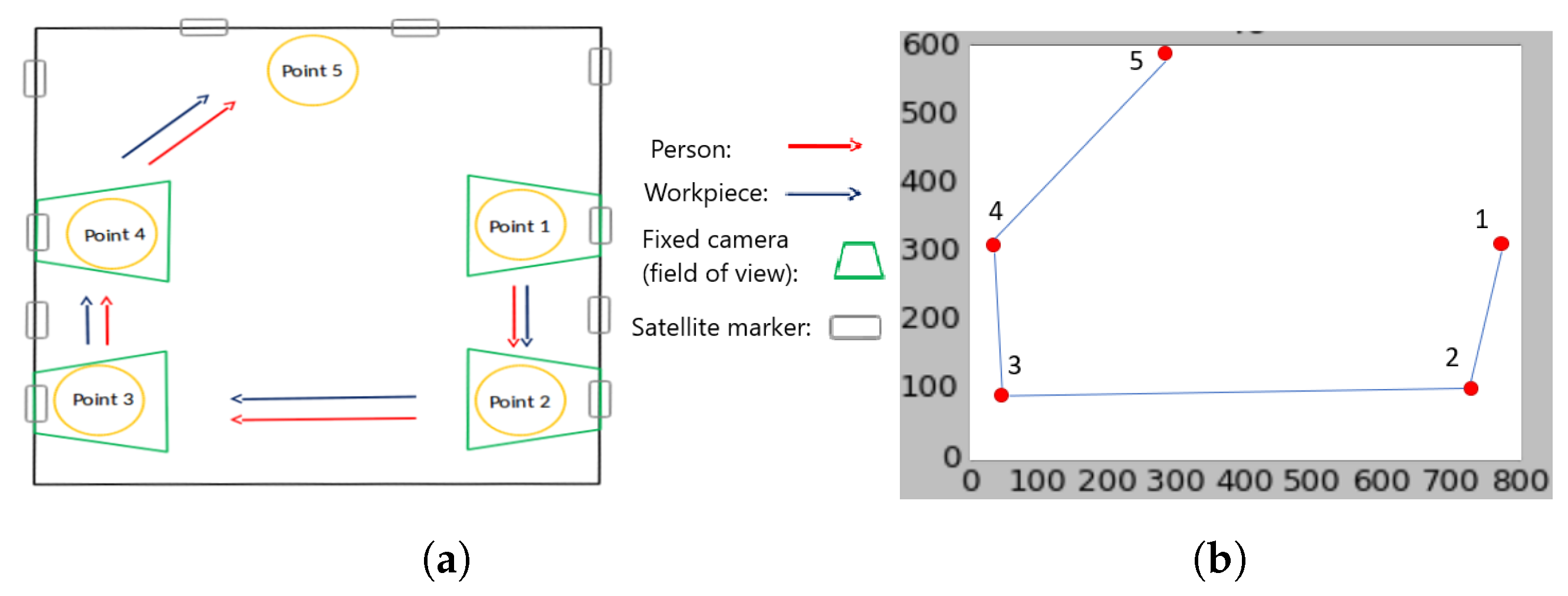
Workspace layout for the experiment is shown in Figure 19 with five locations through which the workpieces were moved. The position of those points as observed by the system is shown in Figure 19b for reference. Static cameras were placed in certain locations, as shown in Figure 19a, along with cameras on the movers, worker and forklift, to track the workpieces.
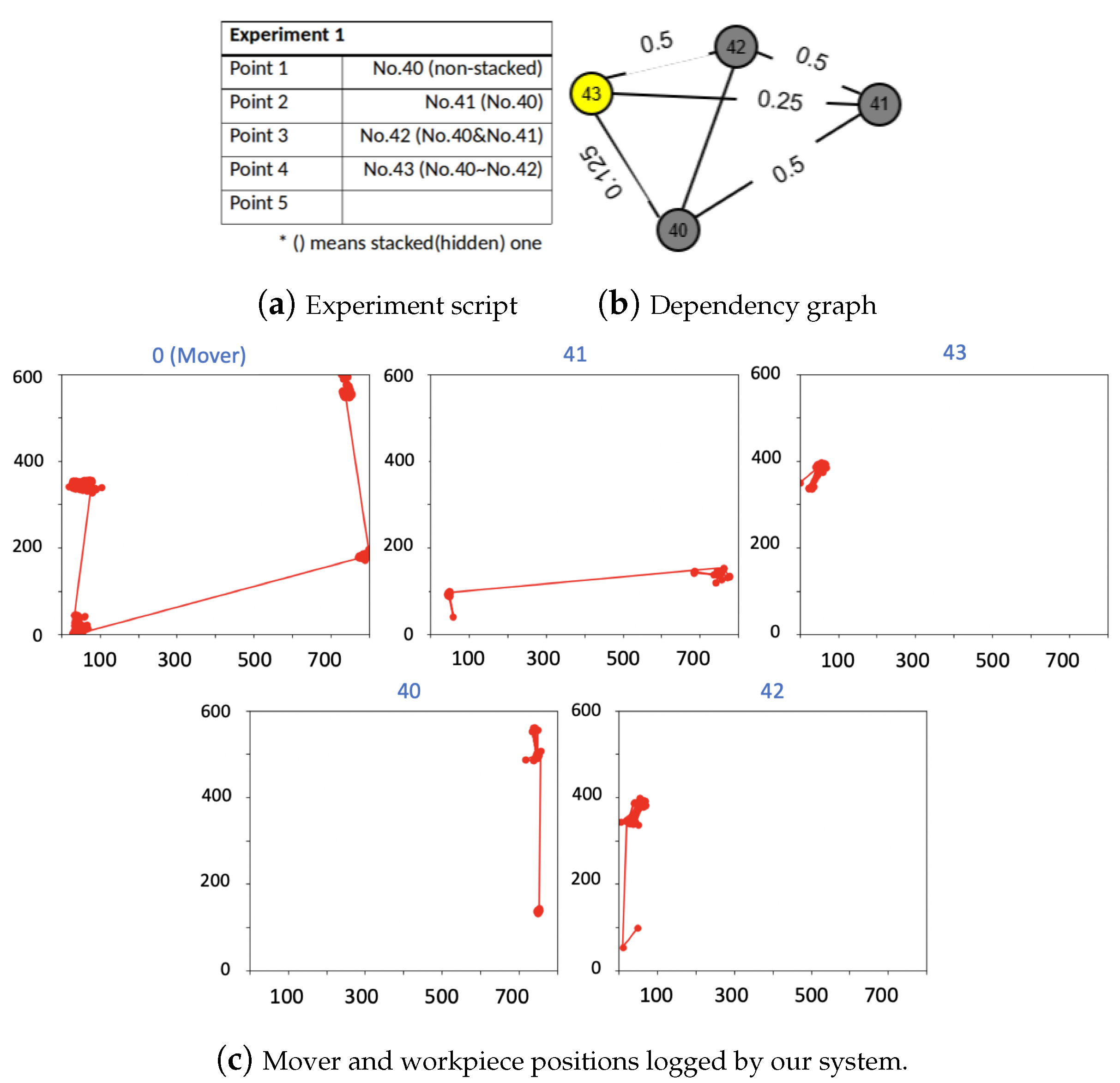
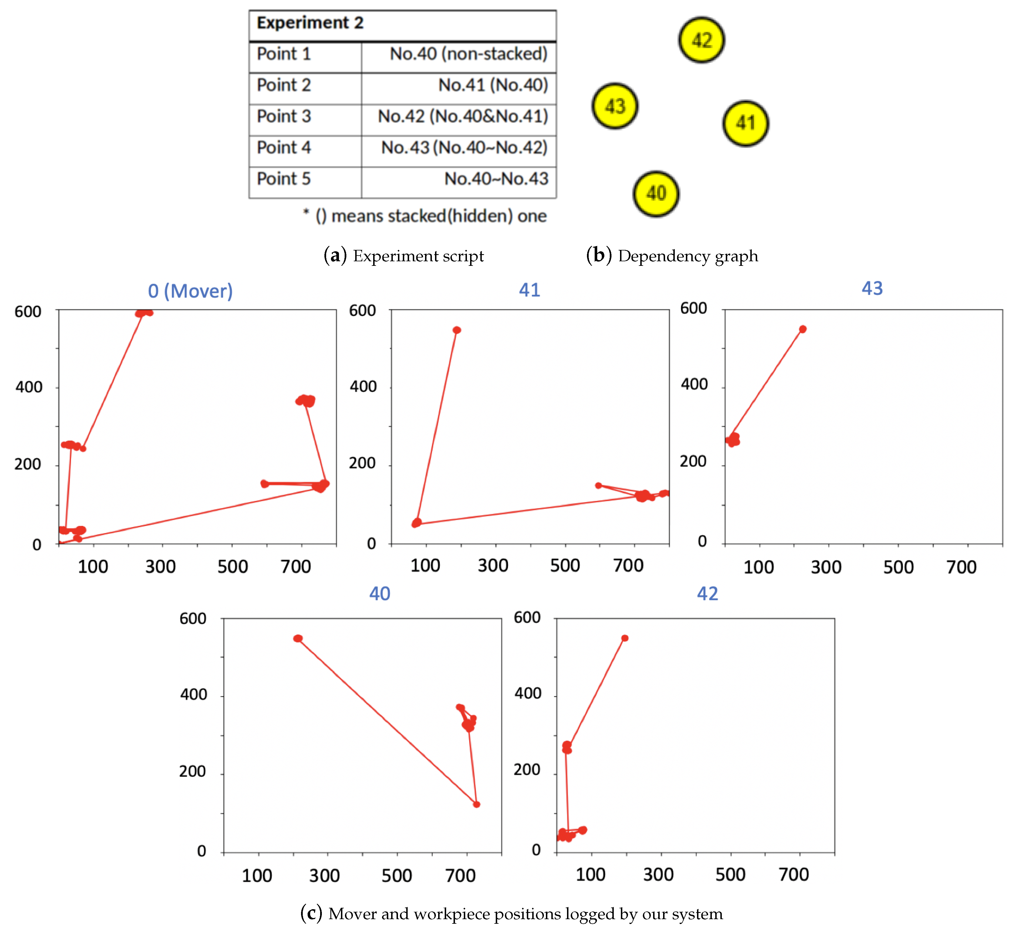
Workpieces are referred through a unique identification numbers (Workpieces 40–45) and are moved from one point on the map to another either visibly or in a stacked condition. After the experiment is complete, the inference module presents its estimation of dependencies between the workpieces as their possible locations. The actual locations of the observed workpieces are also shown in Figure 20, Figure 21 and Figure 22. While the movement of workpieces for the experiment was scripted, the movers interacted with the environment normally. This allowed us to evaluate the ability of our system to detect events and build dependencies with movement of movers in the real world as opposed to fixed cameras in our simulation environment. The objective in each experiment is to evaluate the dependencies or stacks predicted by our system against the ground truth dictated by scripted movements in each of the following experiments. A separation penalty ( γ ) of 0.5 was used in all the experiments. The graphs shown in Figure 20, Figure 21 and Figure 22 only encode the relation between workpieces as opposed to also encoding their position within the workspace. The location of each workpiece, as they were observed throughout the experiment, is shown in separate plots to show the sparseness of direct observations.
Experiment 1: Figure 20 shows the setup and movement of workpieces from Point 1 to Point 4. Workpieces were progressively stacked on top of each other at each point with Workpiece 43 being on top at Point 4. This can be seen on the plots of each workpiece’s raw observation data (Figure 20c). The final dependency graph generated by our system is shown in Figure 20b and shows that each workpiece is connected to every other workpiece. This result is expected as, at each point on the map, each workpiece is added to the stack, generating dependencies to every other workpiece suspected to be in that stack. The edge strength shows the confidence in such dependencies based on levels of separation of events that created the dependency. Since Workpieces 40 and 41 were linked by a direct event, confidence in that dependency is higher, whereas there is less confidence in the dependency of Workpieces 40 with Workpiece 43, due to separation penalty for events that do not directly connect the involved workpieces.
Experiment 2: In this experiment (Figure 21), workpieces were progressively all stacked under Workpiece 43 up until Point 3. At Point 4, the stack gets dispersed and all the workpieces are directly visible at Point 5. Although they might have been stacked before reaching Point 5, since at the end of the experiment all workpieces were individually visible, the generated graph (Figure 21b) shows no dependency between any of them. The likely positions of the workpieces in this case is their last known position as reported in the raw observations (Figure 21c).
Experiment 3: Similar to Experiment 1, in this experiment, workpieces were progressively stacked up to Point 4, where Workpiece 43 is on top and Workpieces 40–42 are stacked under. However, at Point 5, the stack is split with Workpieces 42 and 43 now visible (Figure 22a). This presents a case where we cannot be sure where Workpieces 40 and 41 might be. If the stack order were maintained and the entire group of Workpieces 40-42 were removed from under Workpiece 43, then Workpieces 40 and 41 would only depend on Workpieces 42. However, there is no evidence to support that the stack order was maintained, thus our graph tracks both possibilities until further evidence is available. This is reflected in the final graph (Figure 22b) where Workpieces 42 and 43 are independent of each other but Workpieces 40 and 41 might be stacked with Workpiece 43 or 42. Observing the weights, we see that, although Workpieces 40 and 43 are supposed to be separated by indirect events, a look at Figure 22c shows that Workpiece 40 was accidentally observed at Point 5 and later occluded but within the vicinity of Workpiece 43. The updated location creates direct dependency between Workpieces 40 and 43 as well as between Workpieces 40 and 42 with 0.5 value as opposed to the expected 0.25.

6. Conclusions

Manually locating workpieces when they are not in their expected position is a difficult task in industries such as ship building and construction primarily due to lack of relevant information to conduct the search. In this work, we propose a system to collect information in a crowd-sourced approach through movers, identify events, and reason possible locations for a missing workpiece through a graph-based probabilistic model. The modeled relational information between workpieces is critical to reason possible positions of a missing workpiece and to conduct an informed search when no prior knowledge is available for a worker. Our probabilistic approach in identifying events and possible dependencies preserves ambiguity of location similar to how workers reason locations to search when a workpiece is missing. In our simulated experiments, we showed that our approach significantly reduces the number of search locations when compared to current practice of uninformed searches. We also showed that our proposed system can identify events under real-world conditions by conducting experiments in a real workspace at a functional shipyard.
While the core idea of our approach is to collect information and use high-level reasoning to guide searches, a limitation of our current approach is its dependence on AR markers to both localize the movers and the workpieces. In industrial environments, it might not be possible to densely populate a workspace with static AR markers for mover localization, which leads sparse observations. In the current system, if a static AR marker is not observed, any observation of workpieces by movers is ignored as its position cannot be determined to update the event graphs. This leads to valuable identified events being rendered unusable. With fewer identified events, our system approaches the result of uninformed searches. However, the proposed graph-based inference module itself is not tied to an AR marker-based detection or localization module. Simultaneous Localization and Mapping (SLAM) based systems (e.g. [26]) can be integrated into our current framework to localize the movers with respect to the world. Similarly, AR marker-based detection of the workpieces in our system is but a placeholder for any other off-the-shelf detection module. Several deep learning-based detection packages (e.g., [27]), can replace the AR marker-based workpiece detection module making our framework very flexible to be used in tracking inventory in other applications. Another factor that affects our system performance is the choice of system parameters, such as separation penalty factor and the rate factor for the exponential distribution function. While these parameters have to be set by the user based on known workpiece movement characteristics, our current approach does not refine or learn these parameters when ground truth is available. Current approach can be extended to find the optimal value of these parameters that would best explain the ground truth when ground truth is available. Similarly, if ground truth for workpiece location is available, our approach can further be expanded to learn priors for locations or events for classes of workpieces if they repeatedly follow a pattern of events. While in this paper we introduce and qualify a framework to extract and translate hidden or lost information brought about by mover’s actions, we are currently investigating methods to extract more information and reason from the workspace to facilitate faster pull times of inventory.

Author Contributions

Conceptualization, M.R. and K.S.; funding acquisition, K.S.; supervision, K.S.; methodology, M.R.; software, M.R.; validation, M.R. and G.P.; investigation, M.R. and G.P.; data curation, M.R. and G.P.; writing-original draft, M.R.; writing-review and editing, all authors.

Funding

This research was supported by funding from Tsuneishi Shipbuilding Co., Ltd. The authors thank Nishi Nobuaki, Satoshi Yamauchi and Hirotaka Inoue, from Tsuneishi, for their time and assistance.

Conflicts of Interest

The authors declare no conflict of interest. The funders had no role in the design of the study; in the collection, analyses, or interpretation of data; in the writing of the manuscript, or in the decision to publish the results.

References

  1. Kasim, N.; Liwan, S.R.; Shamsuddin, A.; Zainal, R.; Kamaruddin, N.C. Improving on-site materials tracking for inventory management in construction projects. In Proceedings of the International Conference of Technology Management, Business and Entrepreneurship, Melaka, Malaysia, 18–19 December 2012; pp. 2008–2013. [Google Scholar]
  2. Dakhli, Z.; Lafhaj, Z. Considering materials management in construction: An exploratory study. Logistics 2018, 2, 7. [Google Scholar] [CrossRef]
  3. Navon, R.; Berkovich, O. An automated model for materials management and control. Constr. Manag. Econ. 2006, 24, 635–646. [Google Scholar] [CrossRef]
  4. Grau, D.; Caldas, C.H.; Haas, C.T.; Goodrum, P.M.; Gong, J. Assessing the impact of materials tracking technologies on construction craft productivity. Autom. Constr. 2009, 18, 903–911. [Google Scholar] [CrossRef]
  5. Bell, L.C.; Stukhart, G. Costs and benefits of materials management systems. J. Constr. Eng. Manag. 1987, 113, 222–234. [Google Scholar] [CrossRef]
  6. Harrington, T.C.; Lambert, D.M.; Vance, M.P. Implementing an effective inventory management system. Int. J. Phys. Distrib. Logist. Manag. 1990, 20, 17–23. [Google Scholar] [CrossRef]
  7. Sardroud, J.M.; Limbachiya, M.; Saremi, A. Ubiquitous tracking and locating of construction resource using GIS and RFID. In Proceedings of the 6th GIS Conference and Exhibition (GIS 88), Tehran, Iran, 6 January 2010. [Google Scholar]
  8. Jang, W.S.; Skibniewski, M.J. A wireless network system for automated tracking of construction materials on project sites. J. Civ. Eng. Manag. 2008, 14, 11–19. [Google Scholar] [CrossRef]
  9. Lukowicz, P.; Timm-Giel, A.; Lawo, M.; Herzog, O. Wearit@ work: Toward real-world industrial wearable computing. IEEE Pervasive Comput. 2007, 6, 8–13. [Google Scholar] [CrossRef]
  10. Zhong, R.Y.; Peng, Y.; Xue, F.; Fang, J.; Zou, W.; Luo, H.; Ng, S.T.; Lu, W.; Shen, G.Q.; Huang, G.Q. Prefabricated construction enabled by the Internet-of-Things. Autom. Constr. 2017, 76, 59–70. [Google Scholar] [CrossRef]
  11. Teizer, J. Status quo and open challenges in vision-based sensing and tracking of temporary resources on infrastructure construction sites. Adv. Eng. Inform. 2015, 29, 225–238. [Google Scholar] [CrossRef]
  12. Fang, Q.; Li, H.; Luo, X.; Ding, L.; Rose, T.M.; An, W.; Yu, Y. A deep learning-based method for detecting non-certified work on construction sites. Adv. Eng. Inform. 2018, 35, 56–68. [Google Scholar] [CrossRef]
  13. Teizer, J.; Vela, P.A. Personnel tracking on construction sites using video cameras. Adv. Eng. Inform. 2009, 23, 452–462. [Google Scholar] [CrossRef]
  14. Salonen, T.; Sääski, J.; Hakkarainen, M.; Kannetis, T.; Perakakis, M.; Siltanen, S.; Potamianos, A.; Korkalo, O.; Woodward, C. Demonstration of assembly work using augmented reality. In Proceedings of the 6th ACM international conference on Image and video retrieval, Amsterdam, The Netherlands, 9–11 July 2007; ACM: New York, NY, USA, 2007; pp. 120–123. [Google Scholar]
  15. Aleksy, M.; Vartiainen, E.; Domova, V.; Naedele, M. Augmented reality for improved service delivery. In Proceedings of the 2014 IEEE 28th International Conference on Advanced Information Networking and Applications (AINA), Victoria, BC, Canada, 13–16 May 2014; IEEE: Piscataway, NJ, USA, 2014; pp. 382–389. [Google Scholar]
  16. Mueller, E.T. Commonsense Reasoning: An Event Calculus Based Approach; Morgan Kaufmann: Burlington, MA, USA, 2014. [Google Scholar]
  17. Xu, Y.; Qin, L.; Liu, X.; Xie, J.; Zhu, S.C. A causal and-or graph model for visibility fluent reasoning in tracking interacting objects. In Proceedings of the IEEE Conference on Computer Vision and Pattern Recognition, Salt Lake City, UT, USA, 18–22 June 2018; pp. 2178–2187. [Google Scholar]
  18. Fire, A.; Zhu, S.C. Inferring Hidden Statuses and Actions in Video by Causal Reasoning. In Proceedings of the IEEE Conference on Computer Vision and Pattern Recognition Workshops, Honolulu, HI, USA, 21–26 July 2017; pp. 48–56. [Google Scholar]
  19. Quigley, M.; Conley, K.; Gerkey, B.P.; Faust, J.; Foote, T.; Leibs, J.; Wheeler, R.; Ng, A.Y. ROS: An open-source Robot Operating System. In Proceedings of the ICRA Workshop on Open Source Software, Kobe, Japan, 12–17 May 2009. [Google Scholar]
  20. Neikum, S. ROS, Ar-Track-Alvar Package. Available online: http://wiki.ros.org/ar_track_alvar (accessed on 7 March 2019).
  21. Chae, S.; Seo, J.; Yang, Y.; Han, T.D. ColorCodeAR: Large identifiable ColorCode-based augmented reality system. In Proceedings of the 2016 IEEE International Conference on Systems, Man, and Cybernetics (SMC), Budapest, Hungary, 9–12 October 2016; IEEE: Piscataway, NJ, USA, 2016; pp. 002598–002602. [Google Scholar]
  22. Pentenrieder, K.; Meier, P.; Klinker, G. Analysis of tracking accuracy for single-camera square-marker-based tracking. In Proceedings of the Dritter Workshop Virtuelle und Erweiterte Realitat der GIFachgruppe VR/AR, Koblenz, Germany, 25–26 September 2006. [Google Scholar]
  23. Wang, J.; Olson, E. AprilTag 2: Efficient and robust fiducial detection. In Proceedings of the 2016 IEEE/RSJ International Conference on Intelligent Robots and Systems (IROS), Daejeon, Korea, 9–14 October 2016; IEEE: Piscataway, NJ, USA, 2016; pp. 4193–4198. [Google Scholar]
  24. Barbehenn, M. A note on the complexity of Dijkstra’s algorithm for graphs with weighted vertices. IEEE Trans. Comput. 1998, 47, 263. [Google Scholar] [CrossRef]
  25. Gazebo, Robot Simulation Made Easy. Available online: http://gazebosim.org (accessed on 7 March 2019).
  26. Mur-Artal, R.; Tardós, J.D. Orb-slam2: An open-source slam system for monocular, stereo, and rgb-d cameras. IEEE Trans. Robot. 2017, 33, 1255–1262. [Google Scholar] [CrossRef]
  27. Redmon, J.; Divvala, S.; Girshick, R.; Farhadi, A. You only look once: Unified, real-time object detection. In Proceedings of the IEEE Conference on Computer Vision and Pattern Recognition, Las Vegas, NV, USA, 26 June–1 July 2016; pp. 779–788. [Google Scholar]
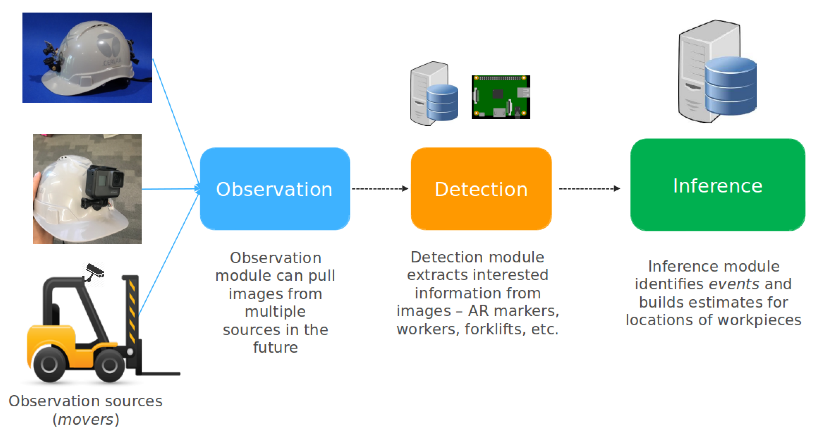
Figure 1. Major modules in our system.
Logistics 03 00021 g001
Figure 2. Cameras attached to worker’s gear to observe the immediate environment. (a) Worker’s helmet fitted with GoPro to wirelessly transmit images to our system. (b) Workers helmet fitted with USB cam attached to a Raspberry-Pi that directly uploads detected part locations to the server.
Logistics 03 00021 g002
Figure 3. Camera view of static markers with known position with respect to origin and workpiece marker, part-150, viewed by our system. Observation of a part marker when a static marker is within view localized the part marker with respect to a defined origin.
Logistics 03 00021 g003
Figure 4. (a) Simulation environment in Gazebo with a fixed camera (known position) and AR markers (workpieces). (b) Image published by the camera that is processed by our system to build the graphs in Section 4.2.
Logistics 03 00021 g004
Figure 5. Overhead observation of the markers (workpieces) as seen by the camera (a). The event graph (b) generated by our system shows all visible workpieces (yellow nodes) and that there is a strong chance of an event happening between Workpieces 3 and 1 as well as between Workpieces 1 and 2. The dependency graph (c) generated by our system shows that there are no dependencies between any of the observed workpieces since they are all directly observable.
Logistics 03 00021 g005
Figure 6. (a) Workpiece configuration where Workpiece 3 is stacked under Workpiece 1; Workpiece 5 is blocked/occluded by an unknown object and Workpiece 2 is moved farther away from Workpiece 1. (b) Event graph shows that there is a high potential for an event between Workpieces 3 and 1 and a decreasing potential between Workpieces 1 and 2. It also shows that Workpiece 3 is no longer visible (grey). It also shows that Workpiece 5 is no longer visible but with no possible events associated with it. (c) Dependency graph shows that Workpiece 3 could be stacked with Workpiece 1 with a dependency weight (edge weight) of 0.5.
Logistics 03 00021 g006
Figure 7. (a) Workpieces 1 and 3 are moved to be stacked under Workpiece 2 while Workpiece 4 is moved closer to Workpiece 5, which was occluded. (b) Event graph shows that potential for an event between Workpieces 1 and 2 is high as Workpiece 1 stacked on top of Workpiece 3, referred to as 1(3), was moved closer to and stacked under Workpiece 2. Event potential between Workpieces 4 and 5 is also increased as Workpiece 4 is moved closer to Workpiece 5’s last known position. (c) Dependency graph shows that Workpiece 1 could be stacked under Workpiece 2 and Workpiece 5 coulde be stacked under Workpiece 4. The edge weight between Workpieces 3 and 2 is 0.25 due to separation penalty for indirect connection.
Logistics 03 00021 g007
Figure 8. (a) Workpiece 4 is moved away from Workpiece 5’s last known position and the entire stack of Workpiece 2 (1,3) is moved closer to and stacked under Workpiece 4. (b) Event graph shows that Workpiece 4 is the only visible workpiece and that there is an event potential between Workpieces 2 and 4 as Workpiece 2 approached Workpiece 4. An event potential also exists between Workpieces 4 and 5 as Workpiece 4 spent significant time near Workpiece 5’s last known position. (c) Dependency graph shows the edge strengths between all workpieces. Edges from direct events have higher weights while indirect (multiple separations) connections have lower weights due to the separation penalty value of 0.5.
Logistics 03 00021 g008
Figure 9. (a) Workpiece 3, with Workpiece 1 stacked under, is removed from Workpiece 4. (b) No event potential exists between Workpieces 3 and 4 as they are too far apart. (c) Since Workpieces 3 and 4 are directly visible, no edge exists between them. Since there is no direct way of knowing how the stack, under Workpiece 4, was split, Workpieces 1, 2 and 5 maintain their edge weights to Workpieces 3 and 4.
Logistics 03 00021 g009
Figure 10. (a) All the stacked pieces except for Workpiece 5 are visible (b) No event potential exists among Workpiece 1–4 as they are too far apart and visible. (c) Since Workpieces 1–4 are directly visible, no dependency edges are present between them. However, our system believes that Workpiece 5 could have been stacked with any of the other workpieces with varying confidence depending on levels of separation.
Logistics 03 00021 g010
Figure 11. (a) Workpieces 1 and 2 are unstacked from Workpieces 3 and 4, respectively. Workpiece 5 is visible again after the unknown object is removed from view. (b) Event graph shows that all workpieces are visible, with event edges eroding between Workpieces 4 and 5 due to larger separation. (c) Since all parts are visible and hence independent, there are no edges in the updated dependency graph.
Logistics 03 00021 g011
Figure 12. (a) Dependency graph showing all possible workpieces under which Workpiece 1 might be stacked for the state shown in Figure 9 with γ set to 0.5. (b) Confidence of finding Workpiece 1 in each possible location calculated from normalized edge weights.
Logistics 03 00021 g012
Figure 13. (a) Dependency graph for Workpiece 1 for the frame in Figure 9 with γ set to 1.0. Since there is no separation penalty, chained dependencies get the same weight as direct ones. (b) Confidence of finding Workpiece 1 in each possible location is uniform in this case.
Logistics 03 00021 g013
Figure 14. (a) Gazebo Simulation environment with nine fixed cameras monitoring stack locations and 11 workpieces scattered within the environment. (b) CAD models of workpieces used in shipping with AR markers attached to them to recognize their ID and position. (c) Sample image published (by Camera 4) that is received and processed by our system during the experiment.
Logistics 03 00021 g014
Figure 15. (a) Path (blue) followed by Workpiece 74 to get stacked under Workpiece 122 (First stack). The stack is then moved along another path (green) and stacked under Workpiece 122 (second stack). (b) G d e p e n d e n c y after performing the second stack in the simulated environment. The graph shows that Workpiece 74 was last observed near Workpiece 115’s previous position and that Workpiece 115 was observed near Workpiece 122. The edges on Workpiece 74 show that it could be stacked with Workpiece 115 and that Workpiece 115 could in turn be stacked with Workpiece 122.
Logistics 03 00021 g015
Figure 16. The figures above highlight that the dependency graph and, as a result, the initial search locations are dependent on observed interactions while being independent of other workpieces that show up in the workspace. This is shown in the dependency graphs in (a) where the number of workpieces, N, within the environment is increased to 30 and in (b) where it is increased to 40. While these new positions become possible search locations in an uninformed search strategy, our search is always initially limited to the number of workpieces that Workpiece 74 interacted with through observed events.
Logistics 03 00021 g016
Figure 17. Representation of information that our approach captures against current baseline to search for missing Workpiece 74 when there are N = 11 potential search locations for the setup shown in Figure 15a. (a) Typical search space when Workpiece 74 is missing and no information on its related events in the past are available. (b) Initial reduced search space, suggested by our system, based on extracted events involving Workpiece 74 and the effect of further events downstream. If Workpiece 74 is not found within the initial suggested locations, the system expands all available workpieces as possible locations.
Logistics 03 00021 g017
Figure 18. Experiment conducted with workers and forklifts (movers) at indoor and outdoor locations at Tsuneishi shipyard in Hiroshima prefecture, Japan. (a) GoPro wireless cameras attached to the worker and forklift (highlighted in orange). Static markers to determine observer location with respect to the environment (highlighted in green). (b) Worker with GoPro attached to hard-hat (orange highlight) interacting with a stack of workpieces gets located within workspace through static markers in the environment (green highlight). (c) Movers (forklift) picking up a workpiece (left) and the point of view from the camera attached to the forklift (right).
Logistics 03 00021 g018
Figure 19. Experiment layout (a) and corresponding plot positions (b) for reference.
Logistics 03 00021 g019
Figure 20. (a) Procedure for Experiment 1 to move workpieces between points (Points 1–4). (b) Fully connected graph showing that all workpieces could be in one stack. (c) Raw observations of each workpiece (Workpieces 40–44) and Mover 0.
Logistics 03 00021 g020
Figure 21. (a) Procedure for Experiment 2 to move workpieces. (b) The graph with no connections shows each workpiece is completely independent of others and should be present in its last seen position. (c) Raw observations from Mover showing path of observed workpieces.
Logistics 03 00021 g021
Figure 22. (a) Procedure in Experiment 3 to move workpieces between points (1–5). (b) The graph shows that Workpieces 40 and 41 could be stacked under either of Workpiece 42 or 43. (c) Raw observations of each workpiece (Workpieces 40–43) and Mover 0.
Logistics 03 00021 g022
Table 1. Table to compare expected locations to search for using our system against guess-based search.
Expected Number of Search Locations
StackingNOur SystemGuessReduced Search Locations
First stack5132
First stack11165
First stack50125.52
Second stack5231
Second stack11264
Second stack50225.523
Simulation results on environment in shown in Figure 15a (N = 11).