
Hierarchically Electrodeposited Nickel/Graphene Coatings for Improved Corrosion Resistance of Ni Foam Flow Field in PEMFC


Abstract
1. Introduction
2. Results and Discussions
2.1. XRD Analysis
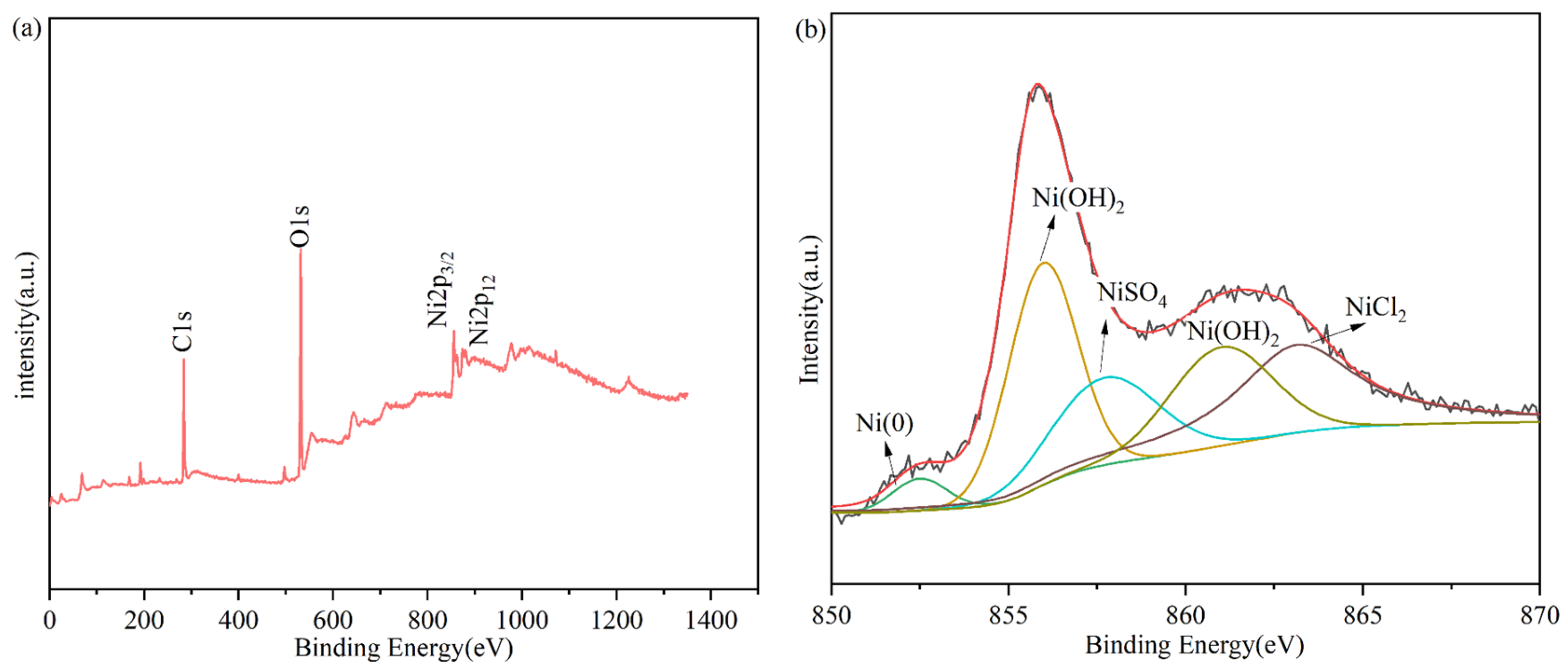
2.2. XPS Analysis
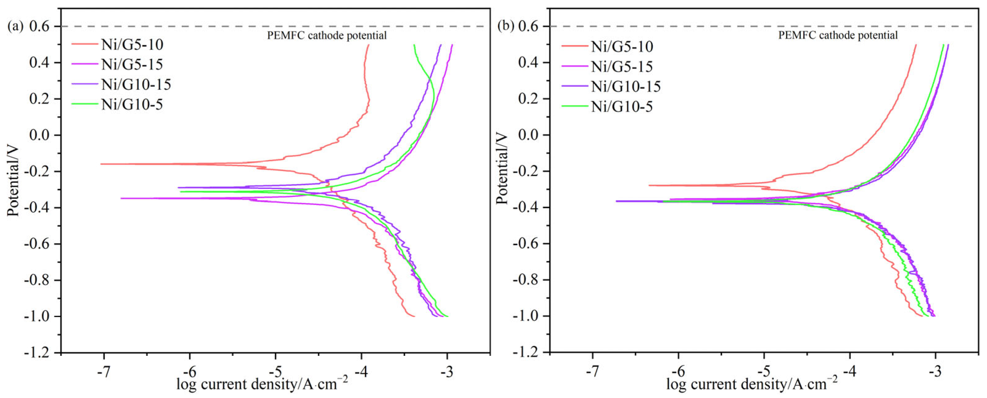
2.3. Tafel Analysis
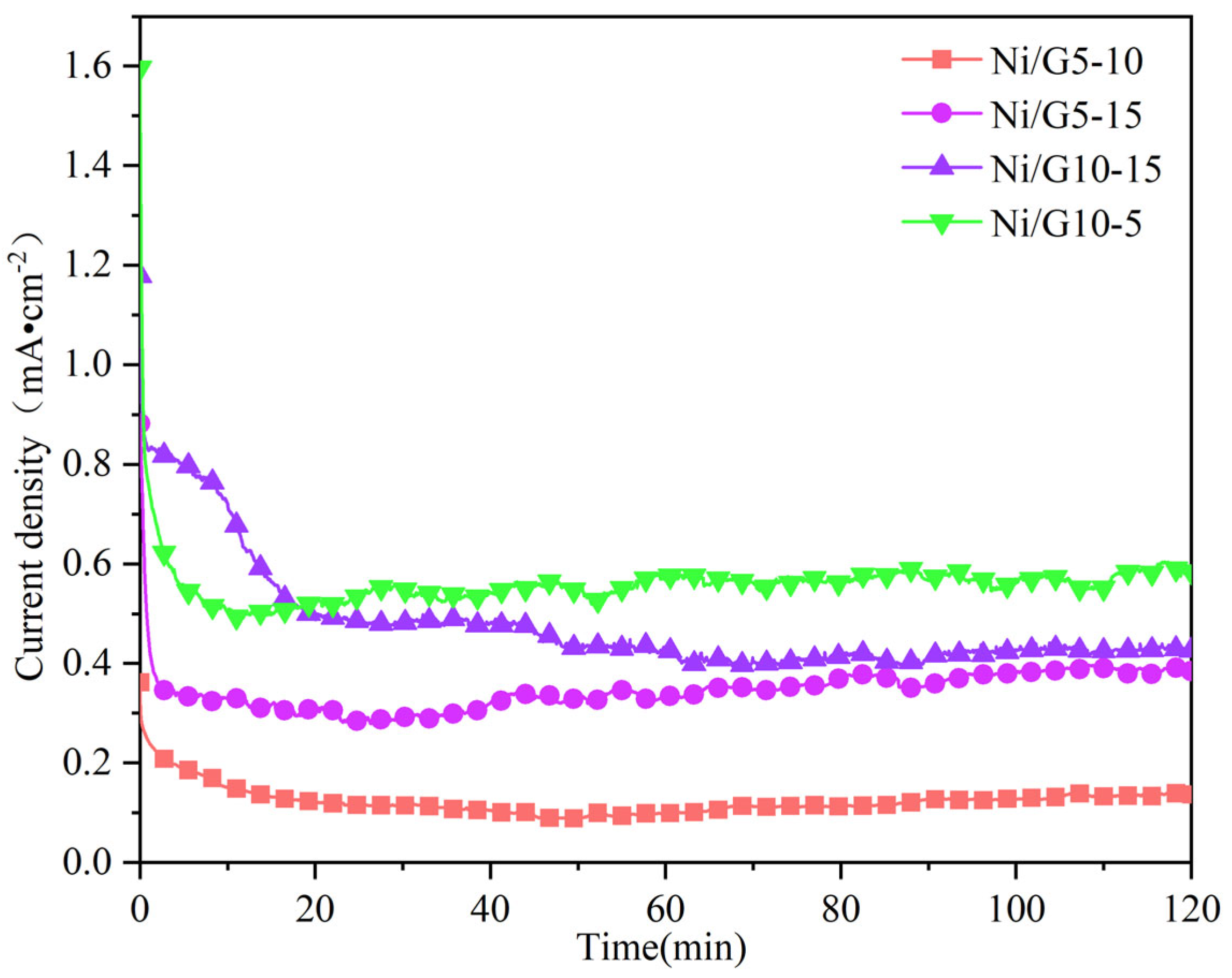
2.4. Constant Potential Analysis
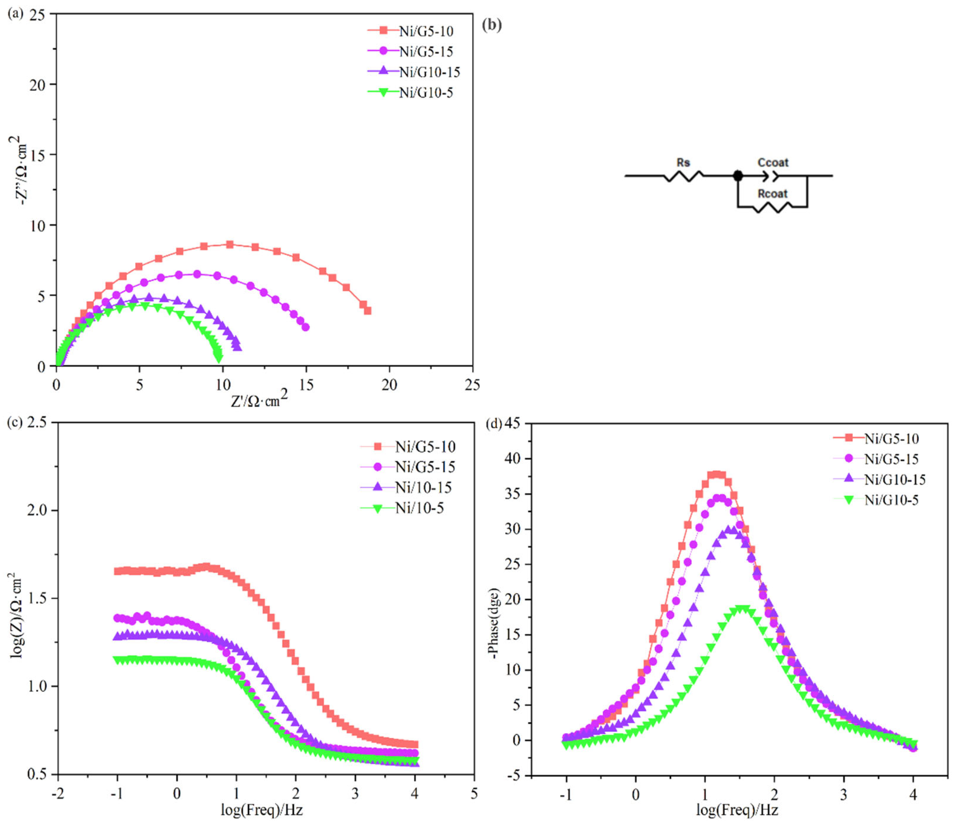
2.5. EIS Analysis
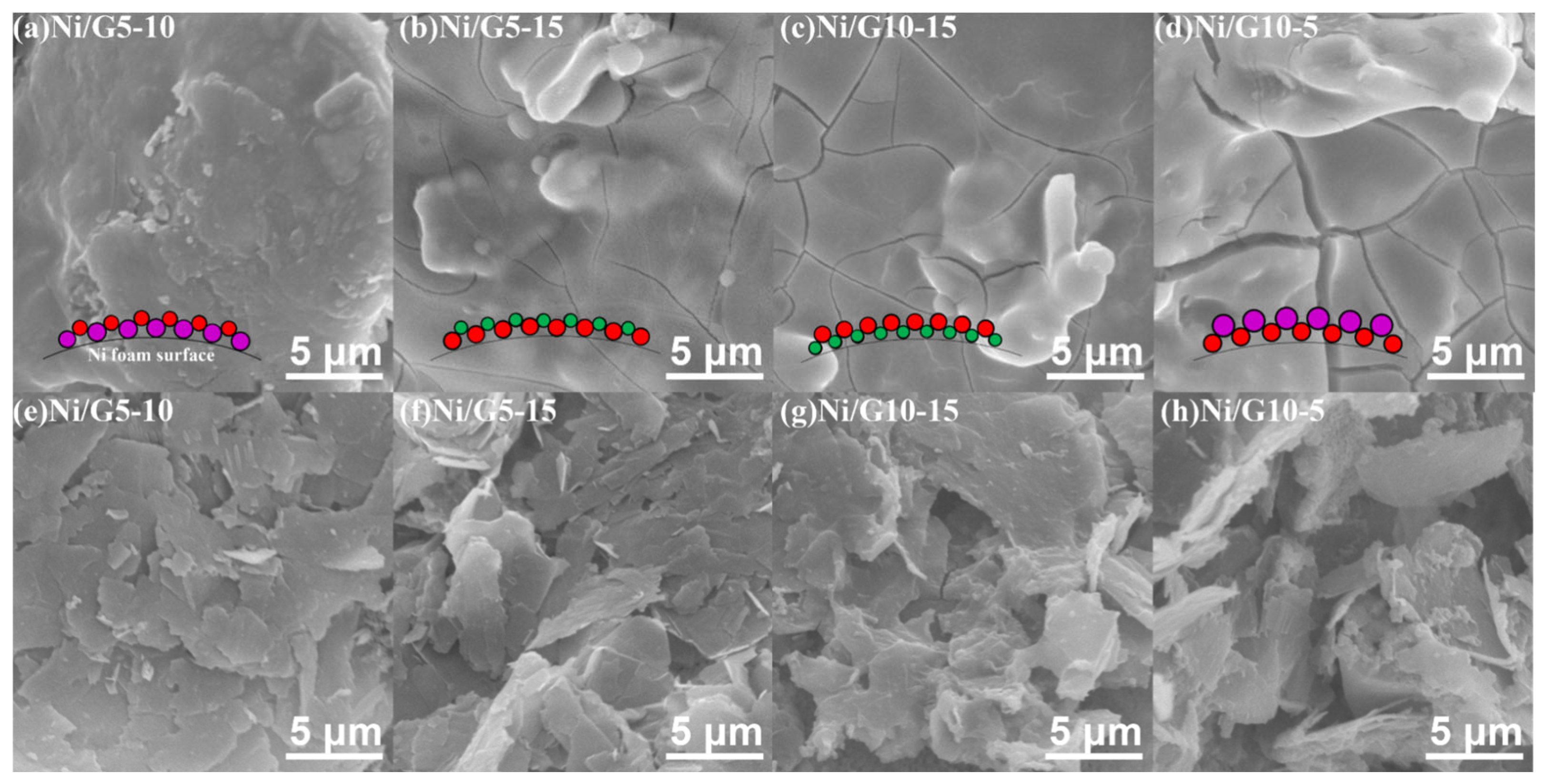
2.6. SEM Analysis
2.7. EDS Analysis
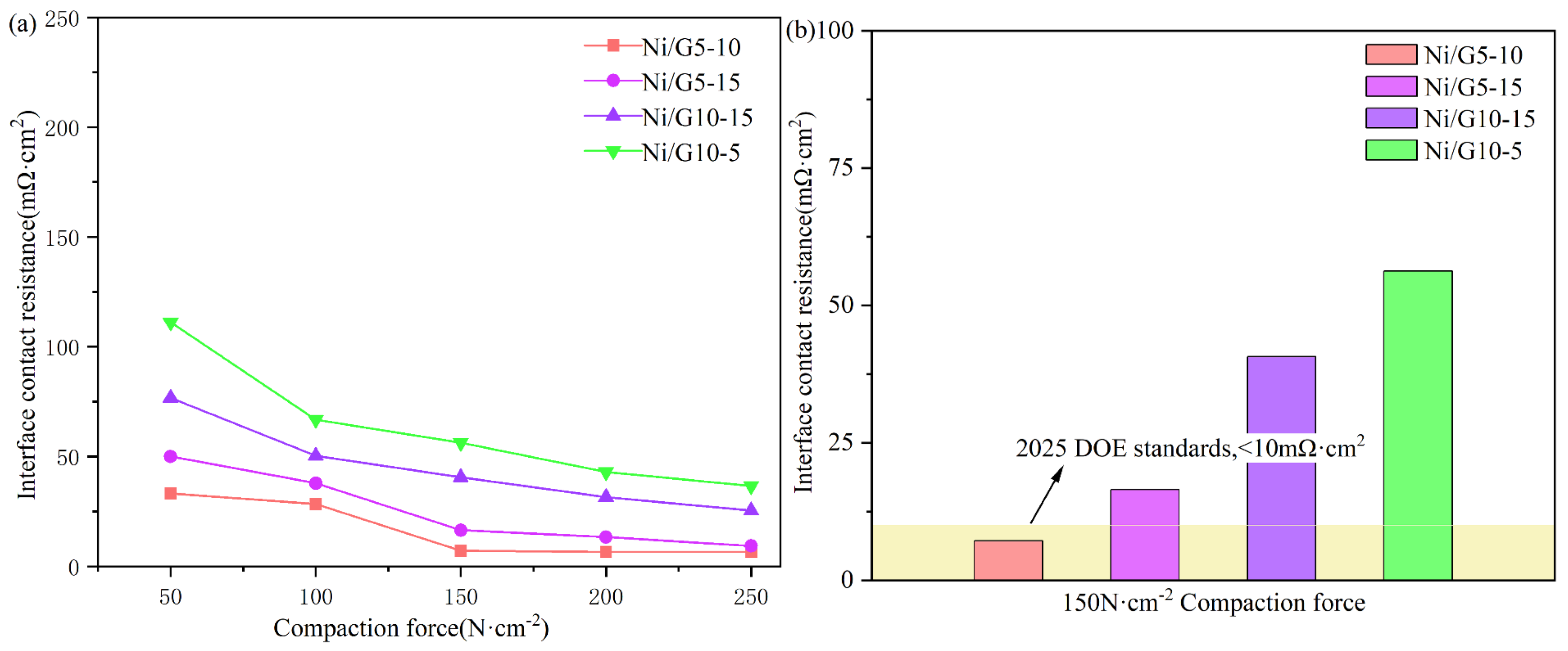
2.8. ICR Analysis
3. Experimental
3.1. Electrodeposition
3.2. Morphology Investigation
3.3. Corrosion Resistance Measurements
4. Conclusions
Author Contributions
Funding
Data Availability Statement
Conflicts of Interest
References
- Gayen, D.; Chatterjee, R.; Roy, S. A review on environmental impacts of renewable energy for sustainable development. Int. J. Environ. Sci. Technol. 2024, 21, 5285–5310. [Google Scholar] [CrossRef]
- Stergaard, P.A.; Duic, N.; Noorollahi, Y. Renewable energy for sustainable development. Renew. Energy 2022, 199, 1145–1152. [Google Scholar] [CrossRef]
- Ahmed, H.; Adebayo, P.; Ahmed, M.; Arbab, A.I. Hydrogen fuel cell technology: Benefits, challenges, and future potential. J. Energy Technol. Policy 2023, 13, 2224–3232. [Google Scholar]
- Aminudin, M.; Kamarudin, S.; Lim, B.; Majilan, E.; Masdar, M.; Shaari, N. An overview: Current progress on hydrogen fuel cell vehicles. Int. J. Hydrogen Energy 2023, 48, 4371–4388. [Google Scholar] [CrossRef]
- Cai, F.; Cai, S.; Tu, Z. Proton exchange membrane fuel cell (PEMFC) operation in high current density (HCD): Problem, progress and perspective. Energy Convers. Manag. 2024, 307, 118348. [Google Scholar] [CrossRef]
- Hermann, A.; Chaudhuri, T.; Spagnol, P. Bipolar plates for PEM fuel cells: A review. Int. J. Hydrogen Energy 2005, 30, 1297–1302. [Google Scholar] [CrossRef]
- Liu, R.; Jia, Q.; Zhang, B.; Lai, Z.; Chen, L. Protective coatings for metal bipolar plates of fuel cells: A review. Int. J. Hydrogen Energy 2022, 47, 22915–22937. [Google Scholar] [CrossRef]
- Kloess, J.P.; Wang, X.; Liu, J.; Shi, Z.; Guessous, L. Investigation of bio-inspired flow channel designs for bipolar plates in proton exchange membrane fuel cells. J. Power Sources 2009, 188, 132–140. [Google Scholar] [CrossRef]
- Liu, Q.; Lan, F.; Zeng, C.; Chen, J.; Wang, J. A review of proton exchange membrane fuel cell’s bipolar plate design and fabrication process. J. Power Sources 2022, 538, 231543. [Google Scholar] [CrossRef]
- Kuan, Y.D.; Wang, C.K.; Yang, C.; Lee, P.C.; Siao, Y.S.; Lee, C.Y. Fuel cell stack design using carbon fiber composites. Sens. Mater. 2020, 32, 4233–4244. [Google Scholar] [CrossRef]
- Gomez Sanchez, A.; Franco Luján, V.A.; Alfaro López, H.M.; Hernández-Sánchez, L.; Cruz-Martínez, H.; Medina, D.I. carbon material-reinforced polymer composites for bipolar plates in polymer electrolyte membrane fuel cells. Polymers 2024, 16, 671. [Google Scholar] [CrossRef] [PubMed]
- Wenkai, L.; Zhiyong, X.; Haodong, Z. Current status of research on composite bipolar plates for proton exchange membrane fuel cells (PEMFCs): Nanofillers and structure optimization. RSC Adv. 2024, 14, 7172–7194. [Google Scholar] [PubMed]
- Wang, X.Z.; Fan, H.Q.; Muneshwar, T.; Cadien, K.; Luo, J.L. Balancing the corrosion resistance and through-plane electrical conductivity of cr coating via oxygen plasma treatment. J. Mater. Sci. Technol. 2021, 61, 75–84. [Google Scholar]
- McCay, K.; Kongstein, O.E.; Oedegaard, A.; Barnett, A.O.; Seland, F. Soldering a gas diffusion layer to a stainless steel bipolar plate using metallic tin. Int. J. Hydrogen Energy 2018, 43, 9006–9014. [Google Scholar]
- Chanda, U.K.; Behera, A.; Roy, S.; Pati, S. Evaluation of Ni-Cr-P coatings electrodeposited on low carbon steel bipolar plates for polymer electrolyte membrane fuel cell. Int. J. Hydrogen Energy 2018, 43, 23430–23440. [Google Scholar]
- Pukha, V.; Glukhov, A.; Belmesov, A.; Kabachkov, E.; Khodos, I.; Khadem, M.; Kim, D.E.; Karaseov, P. Corrosion-resistant nanostructured carbon-based coatings for applications in fuel cells based on bipolar plates. Vacuum 2023, 218, 112643. [Google Scholar]
- Li, S.; Jin, R.; Li, S. High corrosion resistance and conductivity of Al2O3/CrN coating for metal bipolar plates in PEMFCs: Al2O3 hinders CrN columnar crystals growth. Int. J. Hydrogen Energy 2024, 50, 805–816. [Google Scholar] [CrossRef]
- Kim, Y.S.; Lee, I.S.; Choi, J.Y.; Jun, S.; Kim, D.; Cha, B.C.; Kim, D.W. Corrosion behavior of niobium-coated 316L stainless steels as metal bipolar plates for polymer electrolyte membrane fuel cells. Materials 2021, 14, 4972. [Google Scholar] [CrossRef]
- Chauhan, D.S.; Quraishi, M.; Ansari, K.; Saleh, T.A. Graphene and graphene oxide as new class of materials for corrosion control and protection: Present status and future scenario. Prog. Org. Coat. 2020, 147, 105741. [Google Scholar]
- Wang, Z.; Xia, Y.; Lei, H.; Hu, G. Enhanced corrosion resistance of Ni/Sn nano-electrodeposited metal foam for flow field application in simulated PEMFC cathode environment. Int. J. Hydrogen Energy 2022, 47, 35412–35422. [Google Scholar] [CrossRef]
- Ollik, K.; Lieder, M. Review of the application of graphene-based coatings as anticorrosion layers. Coatings 2020, 10, 883. [Google Scholar] [CrossRef]
- Lee, Y.H.; Li, S.M.; Tseng, C.J.; Su, C.Y.; Lin, S.C.; Jhuang, J.W. Graphene as corrosion protection for metal foam flow distributor in proton exchange membrane fuel cells. Int. J. Hydrogen Energy 2017, 42, 22201–22207. [Google Scholar] [CrossRef]
- Wang, J.; Min, L.; Fang, F.; Zhang, W.; Wang, Y. Electrodeposition of graphene nano-thick coating for highly enhanced performance of titanium bipolar plates in fuel cells. Int. J. Hydrogen Energy 2019, 44, 16909–16917. [Google Scholar] [CrossRef]
- Liu, Y.; Min, L.; Zhang, W.; Wang, Y. High-performance graphene coating on titanium bipolar plates in fuel cells via cathodic electrophoretic deposition. Coatings 2021, 11, 437. [Google Scholar] [CrossRef]
- Yu, F.; Wang, K.; Cui, L. Vertical-graphene-reinforced titanium alloy bipolar plates in fuel cells. Adv. Mater. 2022, 34, 2110565. [Google Scholar]
- Pandey, U.; Singh, A.; Sharma, C. Development of anti-corrosive novel nickel-graphene oxide-polypyrrole composite coatings on mild steel employing electrodeposition technique. Synth. Met. 2022, 290, 117135. [Google Scholar] [CrossRef]
- Mu, J.; Gao, F.; Cui, G.; Wang, S.; Tang, S.; Li, Z. A comprehensive review of anticorrosive graphene-composite coatings. Prog. Org. Coat. 2021, 157, 106321. [Google Scholar]
- Rekha, M.; Kumar, M.P.; Srivastava, C. Electrochemical behaviour of chromium-graphene composite coating. RSC Adv. 2016, 6, 62083–62090. [Google Scholar]
- Kumar, M.P.; Singh, M.P.; Srivastava, C. Electrochemical behavior of Zn-graphene composite coatings. RSC Adv. 2015, 5, 25603–25608. [Google Scholar]
- Jabbar, A.; Yasin, G.; Khan, W.Q.; Anwar, M.Y.; Korai, R.M.; Nizam, M.N.; Muhyodin, G. Electrochemical deposition of nickel graphene composite coatings: Effect of deposition temperature on its surface morphology and corrosion resistance. RSC Adv. 2017, 7, 31100–31109. [Google Scholar]
- Sun, C.; Hu, G.; Cao, L.; Pan, T.; Guo, C.; Xia, Y. Ni/graphene coating for enhanced corrosion resistance of metal foam flow field in simulated pemfc cathode environment. ACS Omega 2024, 9, 29797–29804. [Google Scholar] [CrossRef] [PubMed]
- Yigit, O.; Dikici, B.; Senocak, T.C.; Ozdemir, N. One-step synthesis of nano-hydroxyapatite/graphene nanosheet hybrid coatings on Ti6Al4V alloys by hydrothermal method and their in-vitro corrosion responses. Surf. Coat. Technol. 2020, 394, 125858. [Google Scholar] [CrossRef]
- Nesbitt, H.; Legrand, D.; Bancroft, G. Interpretation of Ni2p XPS spectra of Ni conductors and Ni insulators. Phys. Chem. Miner. 2000, 27, 357–366. [Google Scholar] [CrossRef]
- Saldan, I.; Lewin, E.; Dobrovetska, O.; Karlsson, D.; Bilan, O.; Kuntyi, O. Surface analysis of nickel nanomaterials electrodeposited on graphite surface. Micro Nano Lett. 2019, 14, 1233–1237. [Google Scholar] [CrossRef]
- Michał, G.; Mohammad, A.; Gregory, J. Surface science and electrochemical analysis of nickel foams. ACS Appl. Mater. Interfaces 2012, 4, 3012–3021. [Google Scholar]
- Prieto, P.; Nistor, V.; Nouneh, K. XPS study of silver, nickel and bimetallic silver-nickel nanoparticles prepared by seed-mediated growth. Appl. Surf. Sci. 2012, 258, 8807–8813. [Google Scholar] [CrossRef]
- Siddaiah, A.; Kumar, P.; Henderson, A.; Misra, M.; Menezes, P.L. Surface energy and tribology of electrodeposited Ni and Ni-graphene coatings on steel. Lubricants 2019, 7, 87. [Google Scholar] [CrossRef]
- Wang, H.; Sweikart, M.A.; Turner, J.A. Stainless steel as bipolar plate material for polymer electrolyte membrane fuel cells. J. Power Sources 2003, 115, 243–251. [Google Scholar] [CrossRef]
- Li, X.; Shen, Q.; Zhang, Y.; Wang, L.; Nie, C. Wear behavior of electrodeposited nickel/graphene composite coating. Diam. Relat. Mater. 2021, 119, 108589. [Google Scholar] [CrossRef]
- Kumar, C.P.; Venkatesha, T.; Shabadi, R. Preparation and corrosion behavior of Ni and Ni-graphene composite coatings. Mater. Res. Bull. 2013, 48, 1477–1483. [Google Scholar] [CrossRef]
- Algul, H.; Tokur, M.; Ozcan, S.; Uysal, M.; Cetinkaya, T.; Akbulut, H.; Alp, A. The effect of graphene content and sliding speed on the wear mechanism of nickel-graphene nanocomposites. Appl. Surf. Sci. 2015, 359, 340–348. [Google Scholar] [CrossRef]
- Li, N.; Xu, H.; Li, X. Tribological properties and corrosion resistance of porous structure Ni-Mo/ZrO2 Alloys. Coatings 2020, 10, 767. [Google Scholar] [CrossRef]


| Icorr (µA·cm−2) | Ecorr (V) | Vcorr (×10−2 mm·y−1) | ||||
|---|---|---|---|---|---|---|
| 50 °C | 80 °C | 50 °C | 80 °C | 50 °C | 80 °C | |
| Ni/G5-10 | 26.14 | 43.80 | −0.159 | −0.278 | 0.283 | 0.473 |
| Ni/G5-15 | 52.51 | 62.25 | −0.348 | −0.355 | 0.568 | 0.673 |
| Ni/G10-15 | 66.27 | 71.70 | −0.289 | −0.366 | 0.716 | 0.775 |
| Ni/G10-5 | 73.54 | 81.14 | −0.312 | −0.368 | 0.795 | 0.877 |
| Samples | Rs (Ω·cm2) | Ccoat | Rcoat (Ω·cm2) | |
|---|---|---|---|---|
| Ccoat-T | Ccoat-P | |||
| 5–10 | 4.28 | 2.21 × 10⁻³ | 0.87 | 19.79 |
| 5–15 | 3.72 | 1.06 × 10⁻³ | 0.85 | 16.09 |
| 10–15 | 3.02 | 2.8 × 10⁻³ | 0.88 | 12.26 |
| 10–5 | 8.35 | 1.05 × 10⁻³ | 0.91 | 9.78 |
Disclaimer/Publisher’s Note: The statements, opinions and data contained in all publications are solely those of the individual author(s) and contributor(s) and not of MDPI and/or the editor(s). MDPI and/or the editor(s) disclaim responsibility for any injury to people or property resulting from any ideas, methods, instructions or products referred to in the content. |
© 2024 by the authors. Licensee MDPI, Basel, Switzerland. This article is an open access article distributed under the terms and conditions of the Creative Commons Attribution (CC BY) license (https://creativecommons.org/licenses/by/4.0/).
Share and Cite
Xia, Y.; Zuo, Q.; Sun, C.; Hu, G.; Fang, B. Hierarchically Electrodeposited Nickel/Graphene Coatings for Improved Corrosion Resistance of Ni Foam Flow Field in PEMFC. Inorganics 2024, 12, 293. https://doi.org/10.3390/inorganics12110293
Xia Y, Zuo Q, Sun C, Hu G, Fang B. Hierarchically Electrodeposited Nickel/Graphene Coatings for Improved Corrosion Resistance of Ni Foam Flow Field in PEMFC. Inorganics. 2024; 12(11):293. https://doi.org/10.3390/inorganics12110293
Chicago/Turabian StyleXia, Yuzhen, Qibin Zuo, Chuanfu Sun, Guilin Hu, and Baizeng Fang. 2024. "Hierarchically Electrodeposited Nickel/Graphene Coatings for Improved Corrosion Resistance of Ni Foam Flow Field in PEMFC" Inorganics 12, no. 11: 293. https://doi.org/10.3390/inorganics12110293
APA StyleXia, Y., Zuo, Q., Sun, C., Hu, G., & Fang, B. (2024). Hierarchically Electrodeposited Nickel/Graphene Coatings for Improved Corrosion Resistance of Ni Foam Flow Field in PEMFC. Inorganics, 12(11), 293. https://doi.org/10.3390/inorganics12110293