Article

Reflective Terahertz Metasurfaces Based on Non-Volatile Phase Change Material for Switchable Manipulation

by
Natsima Sakda
1,2,
Ratchapak Chitaree
2,* and
B. M. Azizur Rahman
1
1
School of Mathematics, Computer Science and Engineering, University of London, London EC1V 0HB, UK
2
Department of Physics, Faculty of Science, Mahidol University, Bangkok 10400, Thailand
*
Author to whom correspondence should be addressed.
Photonics 2022, 9(8), 508; https://doi.org/10.3390/photonics9080508
Submission received: 28 May 2022 / Revised: 4 July 2022 / Accepted: 20 July 2022 / Published: 22 July 2022
(This article belongs to the Special Issue Active/Reconfigurable Metasurfaces)

Abstract

:
Recently, metasurfaces have been investigated and exploited for various applications in the THz regime, including modulators and detectors. However, the responsive properties of the metasurface in THz stay fixed once the fabrication process is complete. This limitation can be modified when integrating the phase change material (PCM), whose states are switchable between crystalline and amorphous, into the metasurface structure. This characteristic of the PCM is appealing in achieving dynamic and customizable functionality. In this work, the reflective metasurface structure is designed as a hexagonal unit deposited on a polyimide substrate. The non-volatile PCM chosen for the numerical study is germanium antimony tellurium (GST). Our proposed phase change metasurface provides two resonant frequencies located at 1.72 and 2.70 THz, respectively; one of them shows a high contrast of reflectivity at almost 80%. The effects of geometrical parameters, incident angles, and polarization modes on the properties of the proposed structure are explored. Finally, the performances of the structure are evaluated in terms of the insertion loss and extinction ratio.

1. Introduction

Over the past decade, metamaterials and metasurfaces have attracted considerable attention from researchers in various research areas due to their fascinating and extraordinary properties. Such metamaterial is often defined as “The periodic structures have the ability to simulate homogeneous materials whose specific properties do not exist in natural materials” [1,2]. Since the discovery of unnatural properties from the pioneering works of V. Vecelago [3], J.B. Pendry, and D.R. Smith [4,5,6], interest in the metamaterials has grown. A number of unconventional features of metamaterials—for example negative refractive index [7,8,9], negative permittivity and permeability [10,11,12], cloaking [13,14,15,16], near-zero index [17,18,19,20,21], surface plasmon [22,23,24,25,26,27], and extraordinary transmission [28,29,30]—have been focused. One of the potential areas that exploits metamaterials and metasurfaces is in Terahertz (THz) radiation. The THz regime is the electromagnetic spectrum with a frequency in the order of 1012 Hz, placed in the gap between infrared and microwave, sometimes known as the “THz gap”, corresponding to the frequencies between 0.3 and 30 THz [31,32]. There are unique properties which make THz radiation an interesting spectrum: (i) non-ionizing radiation with less power compared to x-rays, so it does not have enough energy to damage a cell or living tissue [33,34,35], (ii) strong sensitivity to water molecules [36,37] which could be used to differentiate the hydration level in cancer and normal cell in biosensing [38,39], and (iii) having matching frequencies with the biomolecular bonding, as well as being sensitive to the hydrogen bond and van der Waals force [40,41,42]. Since there is a lack of a THz generation and detection in the development of this research field, the potentials of metasurfaces and metamaterials have been studied and investigated to fulfill the shortage, which has opened up an exciting research area called THz metamaterials and metasurfaces [43,44,45,46].
In a conventional THz device, once the fabrication process has been completed, the exotic properties are fixed and stay unchanged for the usage time. This is considered a limitation of the devices, as opposed to tunable or switchable performances after finishing the construction. One of the most attractive ways that allows the performances of the devices to be tunable is the scaling of the geometrical parameters [47,48,49,50]. However, the scaling method is impractical for an application of a device involving dynamic manipulations. The use of PCM is an interesting alternative. It can switch between crystalline and amorphous states. The attractive property of the PCM originates from the extensive difference in electromagnetic properties during the phase transition. This interesting behavior has opened up the field of switchable devices, whose operation can be executed in several ways such as electrical [51,52,53,54] or optical [55,56] methods. Nowadays, a chalcogenide alloy called germanium antimony telluride, Ge2Sb2Te5 (GST) has become an attractive PCM due to its non-volatile properties, meaning its state of the phase transition can be maintained without consuming any continuous external energy [56,57,58]. The operation of the GST, either in an amorphous or crystalline state, is triggered by applying voltage or laser pulses, which increases the local temperature of the GST either to above the melting temperature or in between the crystallization temperature and the melting point [59]. The promising applications of PCMs are switchable circular dichroism, switchable perfect absorbers or reflectors, and active terahertz photonic devices [60,61,62].
In this paper, the hexagonal metasurface was numerically studied in terms of the reflectance profiles both with and without PCM. The effects of the geometrical parameters, including hexagonal side, thickness of GST, and dielectric substrate, were thoroughly investigated. Moreover, the angle of incidence and the polarization mode were explored in terms of the sensitivity. The performances of the reflector were evaluated using key device parameters, the insertion loss, and extinction ratio.

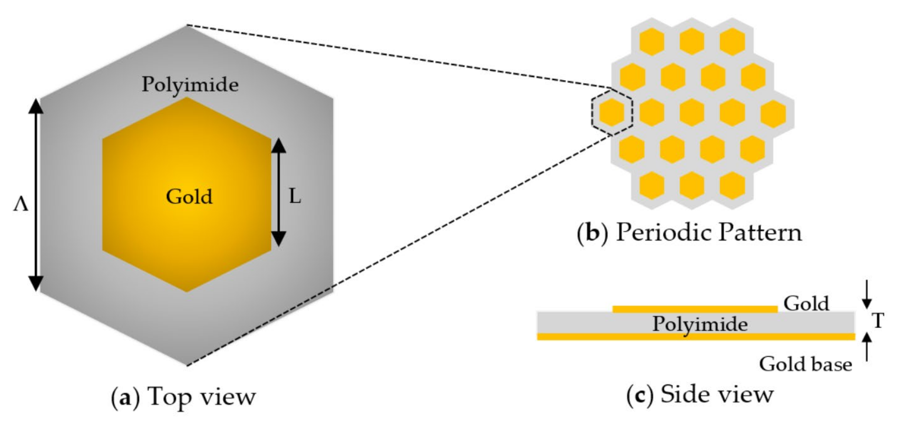
2. The Proposed Hexagonal Unit Cell Structure

The schematic of the proposed unit’s cell structure and periodic pattern is illustrated in Figure 1. The honeycomb pattern in Figure 1b shows the appearance of the metasurface when arranged periodically. Figure 1a depicts the top view of a unit cell structure. The hexagon pattern is made from gold placed on top of a dielectric substrate, such as polyimide, which is non-dispersive and low absorptive at the operating THz radiations [63] with the relative permittivity of 3 + 0.18i [64]. Figure 1c shows the side view of the unit cell; it can be seen that there is a gold layer underneath the polyimide substrate, which is the continuous base layer.
The geometrical parameters of the proposed unit cell structure are composed of the sidelength of hexagonal (L) pattern with the sidelength of the periodicity (Λ). A polyimide sheet of thickness (T) was placed between two thin gold layers, considered here as the thin-film layer. The thickness of the metal layer is greater than the metal skin depth and, in this case, it can be numerically defined as the perfect electric conductor layer [65].

3. Numerical Results and Discussion

The numerical studies presented here were carried out using a finite element method (FEM) in COMSOL Multiphysics commercial software. The study starts with a flat gold hexagonal pattern without a PCM. After that, a GST-based PCM was integrated to the proposed structure. Then the geometrical parameters were optimized to observe their effects on the reflectance spectrum, and finally, the incident angle and polarization sensitivity were investigated.

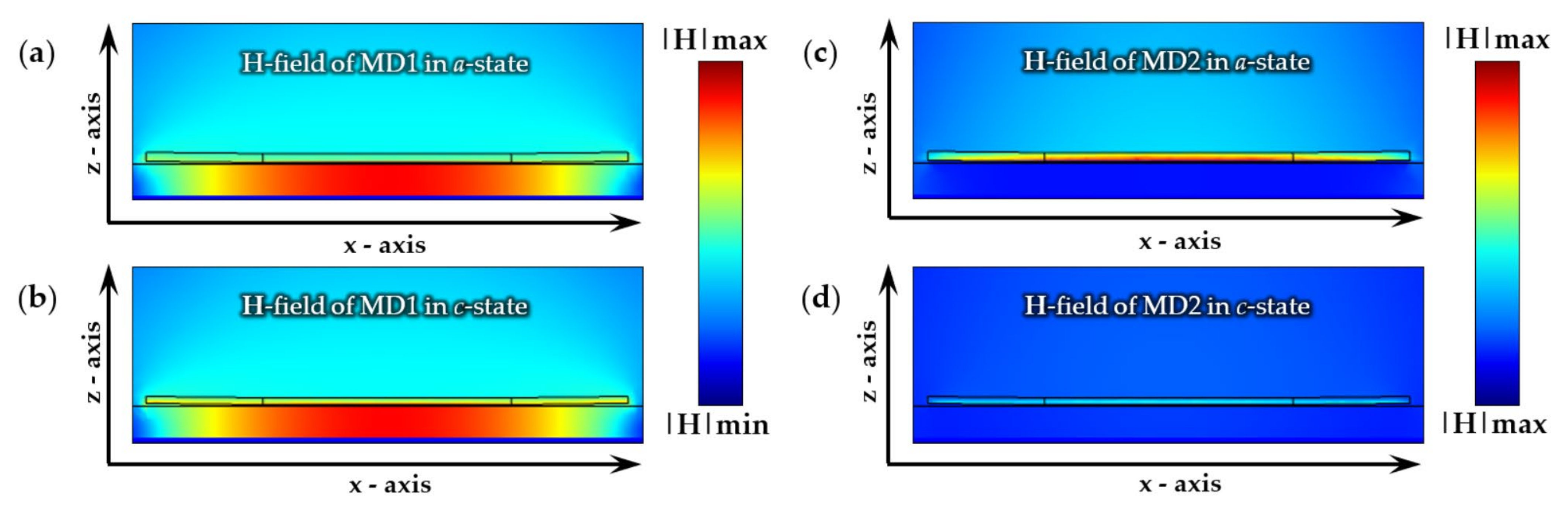
3.1. Electromagnetic Modelling

In order to numerically investigate the proposed structure in this work, there are some involving equations to be considered. The crucial equation here is the Helmholtz equation:
× μ r 1 × E k 0 2 ϵ r i σ ω ϵ 0 E = 0
where the above equation is solved for the electric field at the operating angular frequency ω = 2 π f (which is THz regime in this work), μ r and ϵ r are the relative permeability and permittivity, respectively; σ is the conductivity of the medium, k 0 is the free space wave vector, and ϵ 0 is the permittivity in the vacuum. The reflection coefficient can be simply declared from the Fresnel’s equation. However, the metasurface structure is a three-layer structure, therefore, the Fresnel’s equation needs to be modified for the reflection coefficient as:
r = r 12 + r 23 e 2 i δ 1 + r 12 r 23 e 2 i δ
where r i j is the reflection coefficients from a normal Fresnel’s equation between the two layers, i and j. δ = 2 π d λ 0 n 2 cos θ 2 (d is the thickness of the metasurface layer with the refractive index, n 2 , and refracted angle, θ 2 ) and λ 0 is wavelength in free space. After that, the reflectance value (R) is defined as the modulus-squared of the reflectance coefficient and as the ratio between reflected and incident amplitude of the electric field [66,67], therefore,
R = r 2 = E r E i 2

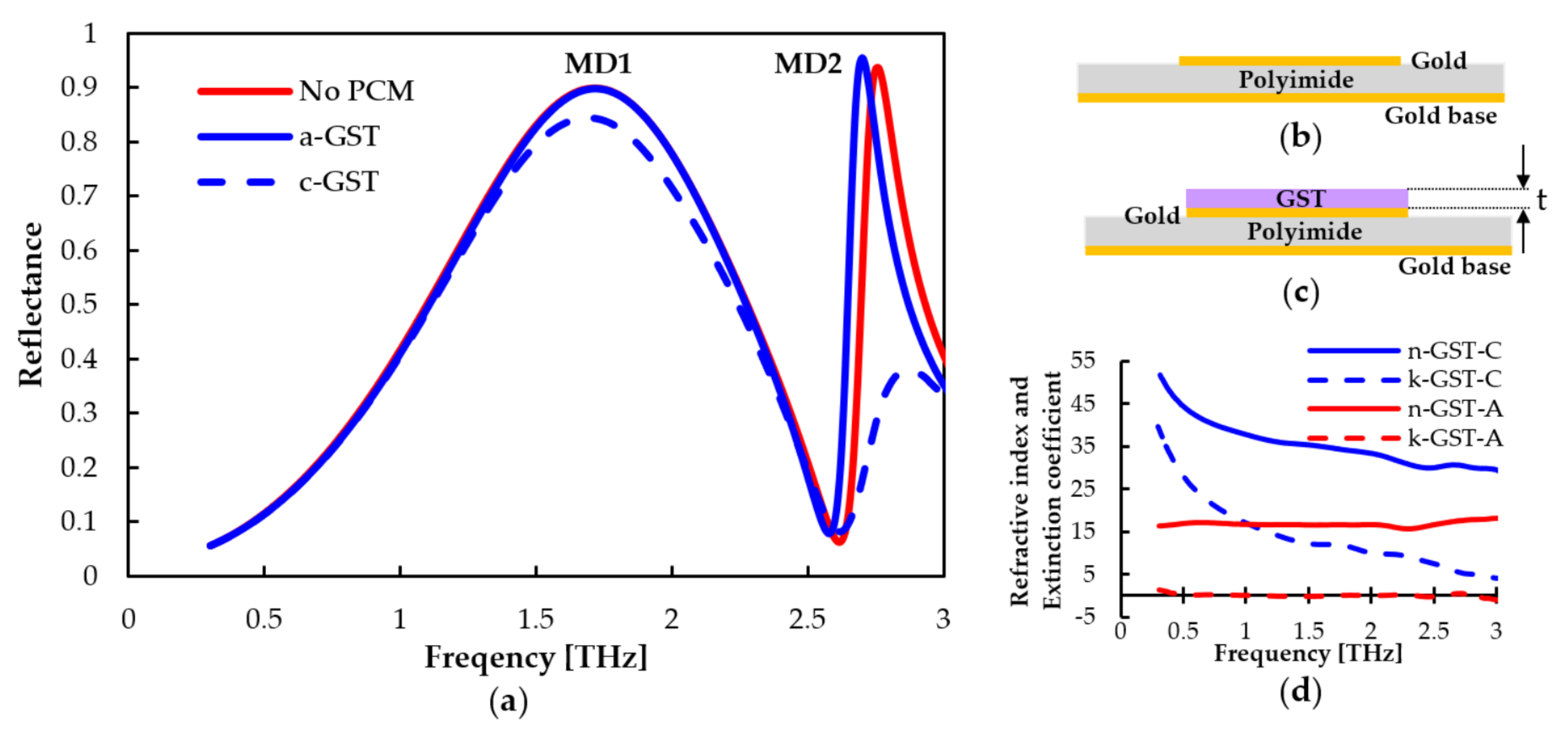
3.2. The Reflectance Profiles

The purpose of this study is to maximize the contrast of the metamaterial reflectance between the amorphous and crystalline states of GST. Initially, the geometrical parameters are optimized from our previous metamaterial structure [68]; the size of a hexagonal unit cell is designated as follows: L = 35 µm, T = 5 µm, and Λ = 70 µm, without the integration of the PCM. Figure 2b shows the structure of the device under the investigation of the resonant frequency on the reflectance spectrum. The reflectance profiles of the proposed hexagonal structures both with and without GST are shown in Figure 2a. The first resonant frequency, designated as the first mode (MD1) from the unit cell without GST, is located at 1.71 THz with its reflectivity of 0.90. This mode is spectrally wider than the second resonant frequency or the second mode (MD2), and its full width at half maximum (FWHM) is calculated as 1.28 THz. The second mode has a higher reflectivity (0.94) at 2.76 THz in comparison to the first one, and its FWHM is calculated as 0.25 THz, which is significantly narrower than the first mode.
Next, one-micron thick GST (t) is integrated into the unit cell structure by placing it on top of the gold periodic pattern, as shown in Figure 2c (GST layer is shaded in violet). The refractive index and extinction coefficient [69] of GST are shown in Figure 2d. The blue lines represent the indices when GST is in the crystalline state (c-state), with solid and dashed lines as refractive index and extinction ratio, respectively. Similarly, when GST is in an amorphous state (a-state), its refractive indices and extinction ratio are shown by red solid and dashed lines, respectively. After adding the GST to the unit cell structure, its reflectance spectra are shown in Figure 2a by blue lines. The numerical results indicate that the proposed phase change metasurface can provide two separate reflectance modes when the GST is in a-state, which is similar to the condition without GST (shown by a solid red line). Note that the MD1 curves overlap, so only the blue curve is visible. The reflectivity of the first mode is 0.90, which is located at 1.72 THz, and the second mode is located at 2.70 THz with a reflectance value of 0.96. When the phase changes from a-state to c-state, the simulation result is shown by a dashed blue line, as in Figure 2a. The first mode remains almost unchanged during the phase transitions. The resonant peak slightly shifts from 1.72 THz to 1.69 THz, with its reflectance value dropping to 0.85. However, a significant change in its reflectance profile value in the second mode is observed, decreasing from 0.94 to 0.16 at 2.70 THz. This gave a reflectance contrast (RC) of 0.78 between amorphous and crystalline states, which can be simply calculated as the difference between reflectance values of a-state and c-state at the considered frequency (RC = Ra − Rc).
The performance of the proposed hexagonal phase change metasurface can be evaluated by two important parameters, which can be defined as:
I n s e r t i o n   L o s s I L = 10   log 10 R a
and
E x t i n c t i o n   R a t i o   E R = 10   log 10 R a R c
where R a   and R c   are the reflectance values at amorphous and crystalline states of GST, respectively, at the resonating frequency of the second mode. In order to optimize the performance of the unit cell reflector, the insertion loss needs to be minimized, while its extinction ratio needs to be maximized. The proposed structure in Figure 2 is found to provide the IL as 0.2 dB and the ER as 7.33 dB.
To understand the behavior of those two resonant frequencies, their field distributions are examined and shown in Figure 3. For the first mode MD1, during the a-state of GST, the side view of the magnetic field distribution in Figure 3a shows the power confinement mostly within the polyimide layer, and the presence of the maximum value is also evident in this dielectric material. Therefore, this mode can be called the magnetic dipole (MD) [70]. When GST switches from a-state to c-state, the magnetic field distribution remains confined in the polyimide layer, as shown in Figure 3b. Clearly, the first mode field distribution is mostly within the dielectric layer and has not been influenced by the GST phase transition. On the contrary, the maximum magnetic field distribution of the second mode appears in the GST layer when the GST is in a-state (Figure 3c). This is also known as the MD. However, when the GST is changed from a-state to c-state, there is a significant difference in the refractive index and extinction coefficient between the two states (as shown in Figure 2d) in the area where most of the energy is confined. This leads to a profound change in the magnetic field distribution for this mode, which then causes a decrease of the second mode, MD2, during the phase transition. To avoid the confusion between the magnetic dipole modes of these two resonances, the notations “MD1” and “MD2” modes are used to designate the magnetic dipoles for the first and the second peaks, respectively.

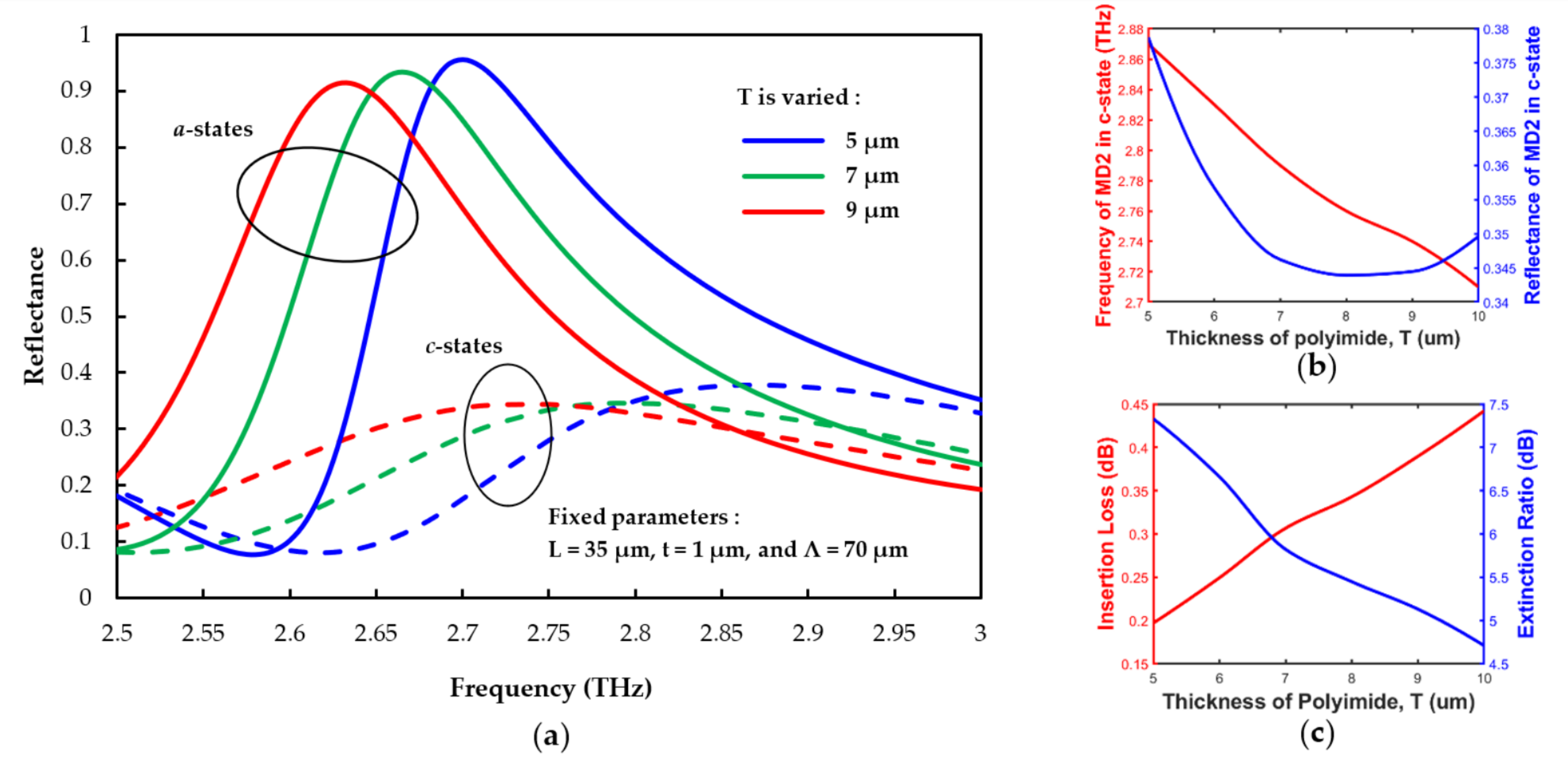
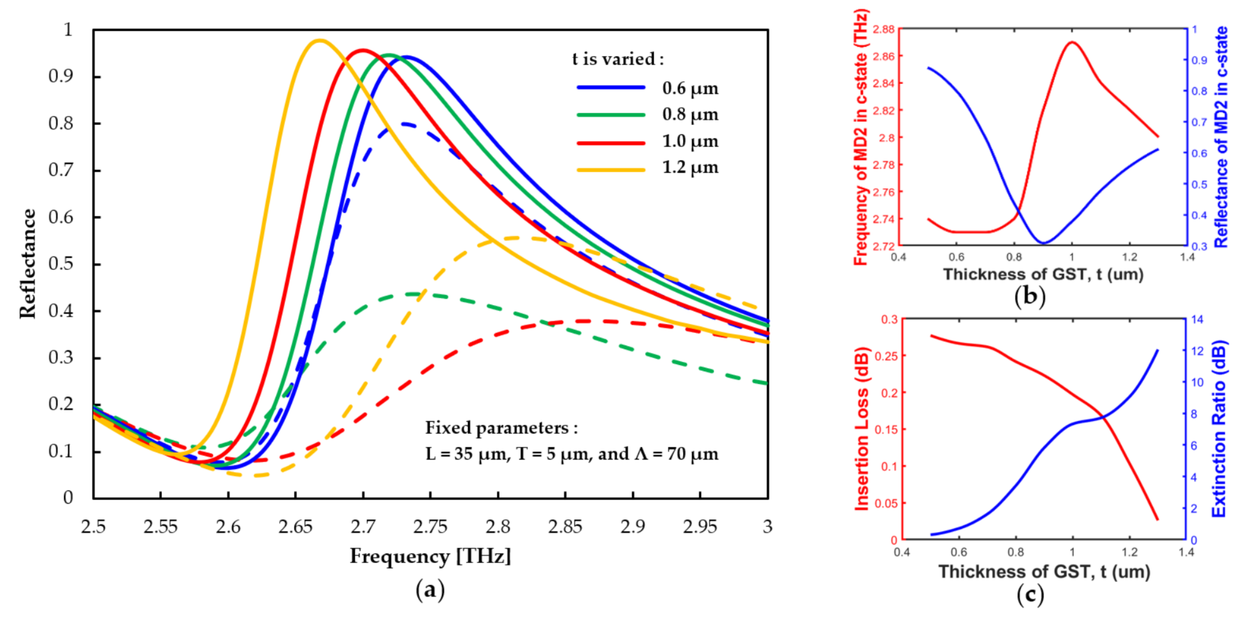
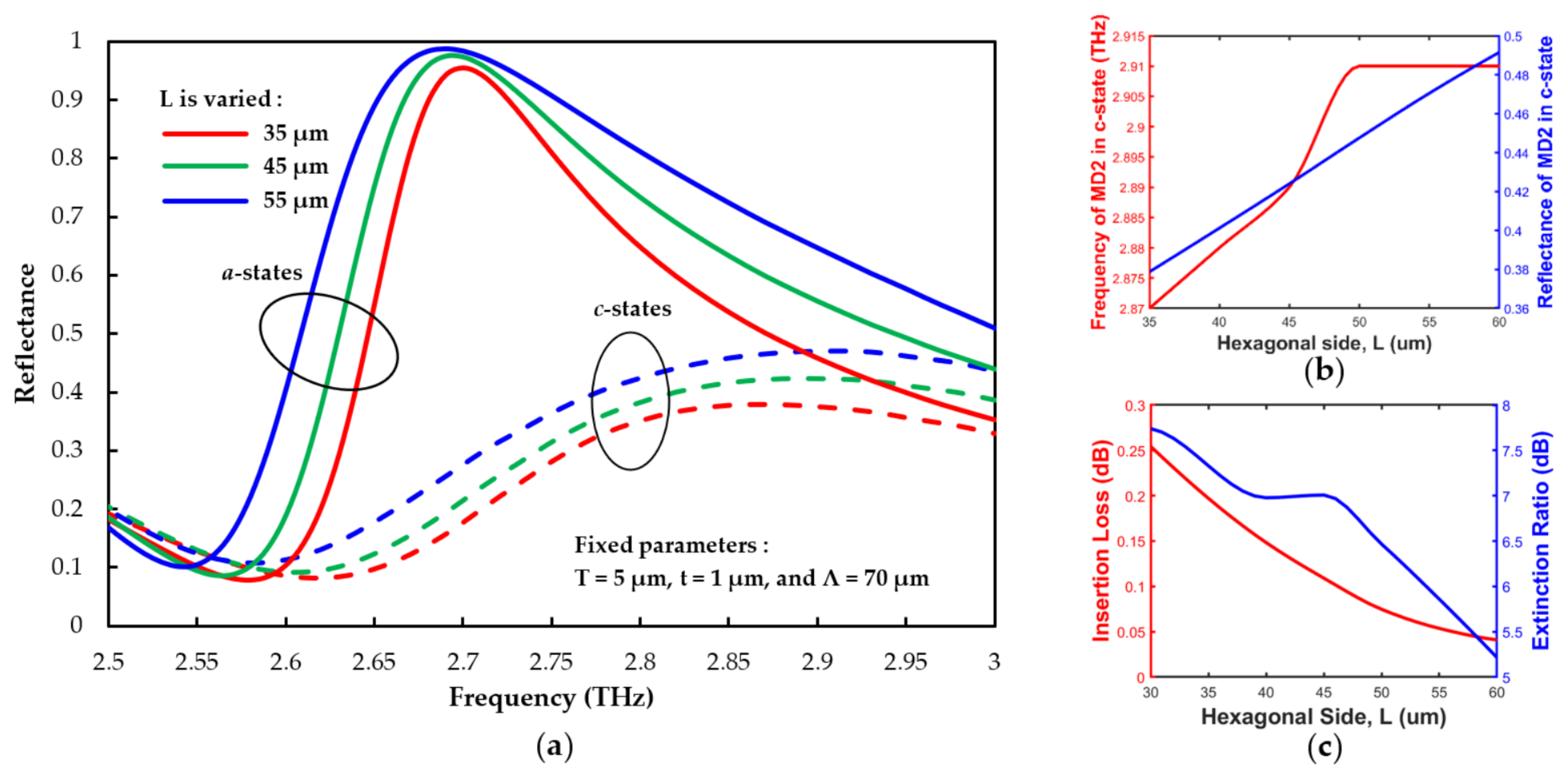
3.3. The Geometrical Parameter Effect

In this section, the geometrical parameters, including polyimide thickness, GST thickness, and hexagonal dimension, will be investigated to show the tunability of the proposed unit cell structure. The performance of the metasurface is again evaluated through insertion loss and extinction ratio values.
Initially, the polyimide thickness (T) is varied for T = 5 µm, 7 µm, and 9 µm, and corresponding reflectances are shown in Figure 4a using blue, green, and red lines, respectively. Reflectances for a-state and c-state of GST are shown by solid and dashed lines, respectively. As there is little change in the MD1, we then monitor only the MD2 around 2.5–3.0 THz to investigate the behavior of the peak and drop of MD2 during the phase transition. In a-state (solid lines), the resonant frequencies of MD2 are 2.70, 2.68, and 2.63 THz, corresponding to the reflectivity values 0.96, 0.93, and 0.91 for the T = 5, 7, and 9 µm, respectively. To see the effect of polyimide thickness, T, the resonant frequency and reflectance value of c-state represented in red and blue lines, respectively, are shown in Figure 4b. The reflectance of the MD2 mode is inversely proportional to the polyimide thickness as the frequency is shifted to the lower values, or polyimide becomes thicker. The minimum reflectivity value represented in the blue line (Figure 4b) is found to correspond to a polyimide thickness of around 8 µm. For the switching performance of MD2, showing the contrast between amorphous and crystalline phases, the result is investigated by insertion loss and extinction ratio using Equations (4) and (5), and the values are illustrated in Figure 4c. The relation between IL and T shows that when the thickness of polyimide increases, the insertion loss also increases, whereas the ER decreases. At the same time, a larger contrast between a and c-states occurs when the polyimide becomes thicker.
Next, the performances of the designed material were also studied as a function of the GST thickness (t). The variation of reflectance for GST thicknesses t = 0.6 µm, 0.8 µm, 1.0 µm, and 1.2 µm are shown in Figure 5a by blue, green, red, and yellow lines, respectively. Reflectances for a-state and c-state of GST are shown by solid and dashed lines, respectively. The frequency-dependent reflection graph is again focused on the region of the MD2, regarding the behavior of the switchable property. For a-state, the MD2 mode resonant frequency is shifted to a smaller frequency when the GST is thicker. For a-state, the MD2 peaks are found to locate at 2.73, 2.72, 2.70, and 2.68 THz with their reflectivity values of 0.94, 0.95, 0.96, and 0.98 for the GST thickness of 0.6 µm, 0.8 µm, 1.0 µm, and 1.2 µm, respectively. The overall performance of the MD2 in c-state illustrated in Figure 5b shows the shifted resonant frequency of MD2 represented by a red line. It shows that the resonant frequency increases and reaches a maximum value of 2.87 THz when the GST thickness increases from 0.8 to 1.0 µm. The following resonant frequency then decreases when the thickness of the GST is greater than 1.0 µm. The reflectivity value of MD2 in c-state is shown by a blue line (Figure 5b). It is evident that the reflectivity value decreases from 0.9 to 0.3 when the GST thickness increases from 0.5 to 0.9 µm. After reaching the minimum value, it subsequently increases when the GST thickness is greater than 0.9 µm. Next, the performance of the phase transition between two states is shown in Figure 5c, where insertion loss and extinction ratio are shown by red and blue lines, respectively. It is evident that for the thicker GST, the insertion loss is lower, whereas the ER becomes higher.
Next, variations of the reflectance spectrum from hexagonal sidelengths, L equal to 35 µm, 45 µm, and 55 µm, are shown in Figure 6a by blue, green, and red lines, respectively. The solid and dashed lines represent the reflectances when the GST is in a-state and c-state, respectively. We again focus only around 2.5 THz to 3.0 THz for the MD2 mode. In the a-state of the GST, the reflectivity values are 0.96, 0.98, and 0.99 at the resonating frequencies of 2.70, 2.71, and 2.71 THz for the hexagonal sides of 35 µm, 45 µm, and 55 µm, respectively. Moreover, it can also be observed that the bandwidth of the peak increases when the hexagonal side increases. For the c-state, the key performance of this state is shown in Figure 6b in which the red line represents the relationship between the resonating frequency of MD2 and the hexagonal sidelength. The relationship is in direct proportion until the L reaches 50 µm; after that, the resonating frequency remains almost constant as the dimension increases. The blue line shows the reflectivity value for each resonant peak in c-state. The reflectivity value increases when the hexagon is bigger. Figure 6c describes the performance of the MD2 due to the phase transition. Insertion loss in the red line and extinction ratio in the blue line similarly decrease as the hexagonal side gets larger.

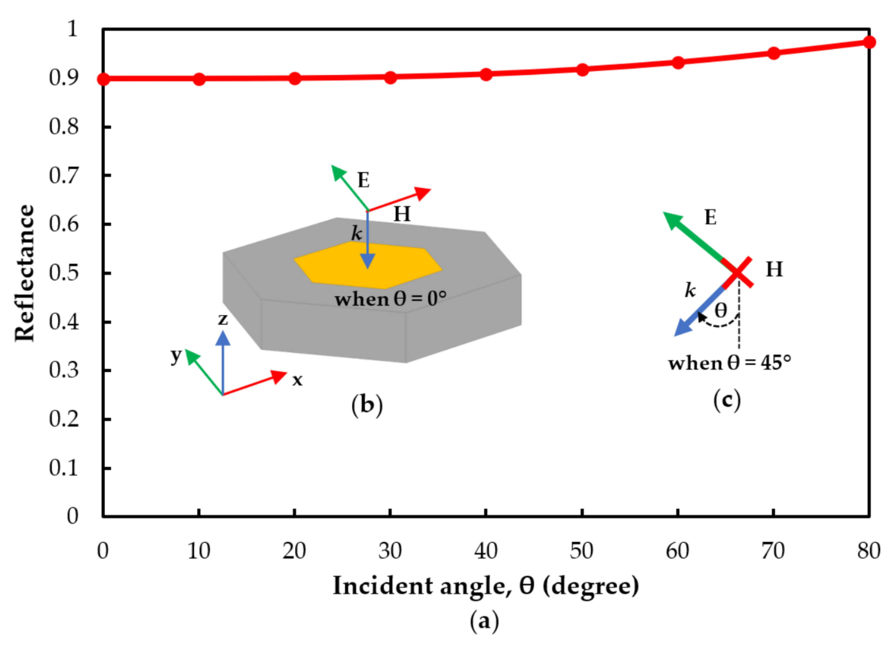
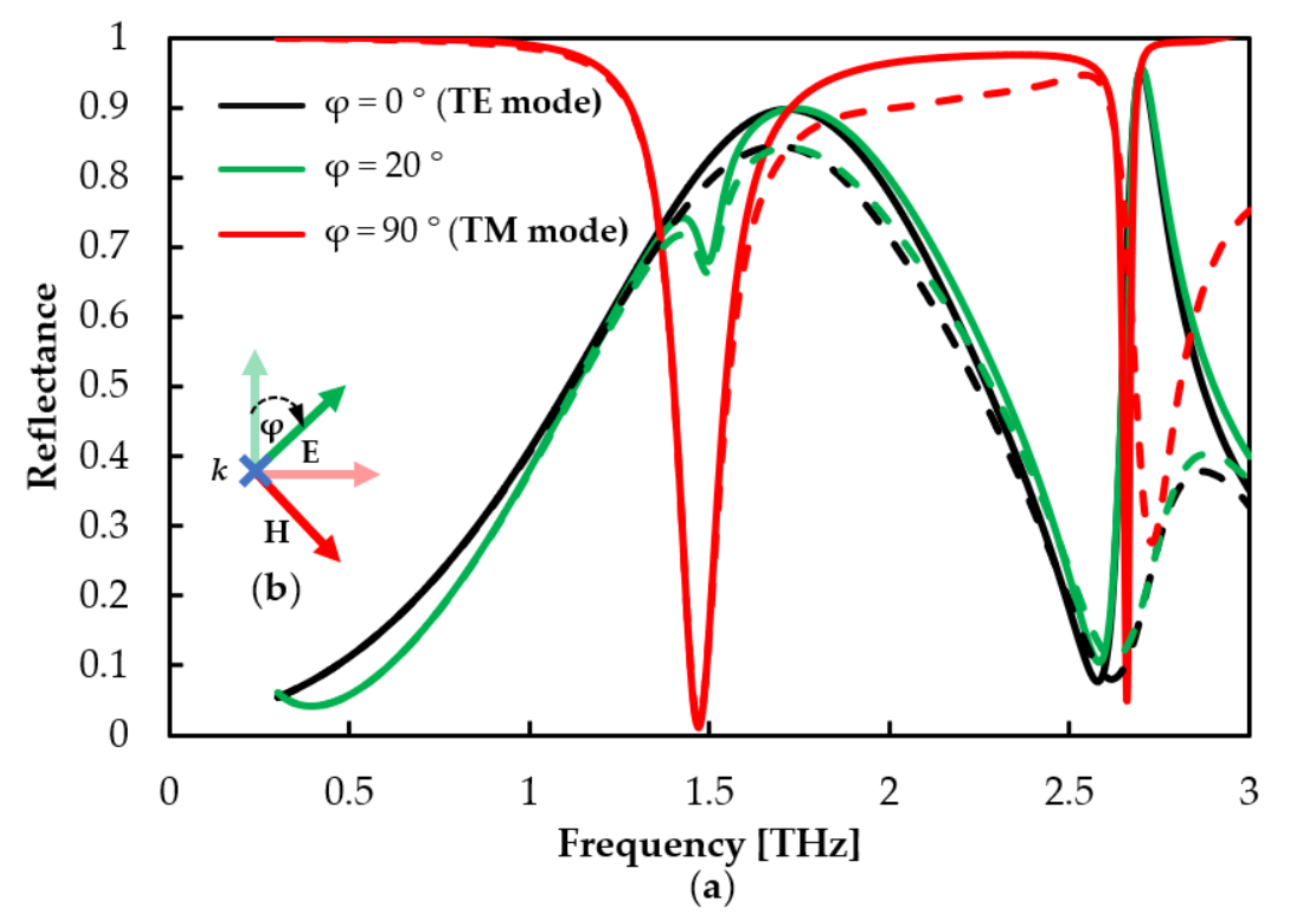
3.4. The Effect of Incident Angle and Polarization Mode

In this section, the effect of the incident angle and the polarization mode will be explored. At the start of the numerical simulations, it is assumed that the incident electric field is in the y-direction and the wave vector, k representing the wave propagating is in the z-direction, perpendicular to the surface of the unit cell structure (shown in Figure 7b). Subsequently, the incident angle (θ) is varied from 0 to 80 degrees (90° is not considered because at this incident angle, the incident field is parallel to the structure) with respect to the z axis, as shown in Figure 7b. This makes the initial mode correspond to the transverse electric (TE) mode. In order to change from TE to transverse magnetic (TM) mode, the initial electric field has to be obtained in x-direction (in Figure 7b). Firstly, our numerical studies show the reflectance profile when the incident angle is varied. The MD1 maintains a high reflectivity for both a-state and c-state of the GST, as shown in Figure 7. The reflectance values for all incident angles above 90% are almost independent on the incident angle. In other words, the MD1 resonance of the proposed reflector can effectively be used in any angle of incidence. However, the second magnetic dipole is strongly sensitive to the incident angle for both a-state and c-state. Therefore, the proposed structure shows a potential for the angle of incidence measurement or a sensing application in which the sensitivity on the incident angle is a required condition.
Next, the effect of the polarization state of an incident beam is investigated and presented in Figure 8a with black, green, and red lines when φ is at 0°, 20°, and 90°, respectively. As shown in the figure, the polarization angles at 0° and 90° correspond to the TE and TM polarization modes, respectively. Here, solid and dashed lines describe the GST in a-state and c-state, respectively. When φ is 0° (TE), the solid black line shows two resonating reflectances at 1.71 and 2.76 THz. At the polarization angle of 20°, the reflectance is described by a solid green line. The reflectance is almost the same as TE mode, but there are two dips appearing around 1.5 THz (clearly be seen) and 2.7 THz (hardly be seen). When the polarization angle increases to 90° (TM), these two dips become more apparent.
They clearly show that the proposed metasurface reflector is strongly dependent on the polarization state. As can be seen in the solid red line (a-state), the TM mode illustrates two resonant dips: the first is at 1.47 THz with the trough going down to 0.01, and the second dip is located at 2.66 THz with a reflectance value of 0.05. The behavior of the dip occurring at the polarization angle of 20° can also be seen from the green line. Hence, the TM mode shows the possibility for sensing applications using the two sharp resonant dips with almost zero reflectivity in a-state. In c-state, the second resonant dip is shifted towards higher frequencies and the reflectance corresponding to the dip increases. In all, the promising usage should go to the first dip because its effective dip remains at a constant frequency.
To show the novelty of our structure, Table 1 presents a comparison of some significant characteristics of the phase change metasurface device in the THz radiation. This table contains information of the reflective type of band, the resonant frequency, nonvolatile or volatile property, contrasting value at the resonant frequency, and the complexity of the periodic pattern.
Our proposed reflective GST metasurface is a non-volatile structure. This has an advantage over a volatile PCM like vanadium dioxide, VO2 [75,76], in terms of the consumption of the external energy to reverse back to its stable state. Table 1 also shows that our proposed structure is a dual-band reflective metasurface located at 1.72 and 2.70 THz, corresponding to significantly differing contrast values of 5% and 78% for MD1 and MD2, respectively. In addition, due to a simple structure of the proposed metasurface, the fabrication process is expected to be less complicated than previous structures. The fabrication for our simple structure can be described as follows: The device fabrication process starts with the deposition of the metal layer (gold) on the silicon wafer by the thermal evaporation method and then a spin-coating technique is utilized to embed the dielectric layer (polyimide) on the metallic layer. Afterwards, the metal layer is deposited again on the dielectric layer. The hexagonal design is shaped by wet etching following the lithography. Finally, the GST layer can be placed on the structure using magnetron sputtering [77,78,79,80,81]. Lastly, the proposed reflective metasurface unit has a promising potential to be integrated into THz-based biosensing systems because of the compatibility between the resonant frequencies and the frequency response of organic molecules [82].

4. Conclusions

In this research, we firstly simulated a hexagonal metasurface with no PCM. The numerical result shows that the proposed structure provides two unique resonant frequencies in THz radiation with high values of reflectivity: 1.71 and 2.76 THz. After that, the phase change material, GST, was integrated into the proposed unit cell structure by placing it on top of the gold film. Initially, the amorphous state of GST was considered. The unit cell of the phase change metasurface provides two fixed resonant frequencies of 1.72 and 2.70 THz with a high reflectivity, and one of them still has high reflectance values after the phase transition. The field distributions of these two peaks clearly show differing magnetic field contours as identified by the magnetic dipoles (MD1 and MD2). The former is located in a polyimide layer, while the latter is confined in the GST layer. After the phase transition of GST from amorphous to crystalline state occurs, there is a minimum change in MD1. In addition, MD2 is found to be confined in the GST layer due to an abrupt change in the GST refractive index.
The effect of substrate thickness, phase change material thickness, and hexagonal sidelength were also investigated to observe the effect on the reflectance profile. The numerical study showed the shifting of frequency when the size of unit cell structure is changed. This confirms the ability to tune and optimize the performances of the proposed device. The performances of the proposed metasurface unit cell were evaluated by two important parameters: insertion loss and extinction ratio. The results showed that the thinner polyimide and thicker GST provide a better performance of the proposed structure. Finally, we showed that the properties of our proposed unit cell are polarization dependent and incident-angle insensitive.

Author Contributions

Conceptualization, B.M.A.R., R.C. and N.S.; methodology, N.S.; software, B.M.A.R. and N.S.; validation, B.M.A.R. and R.C.; formal analysis, N.S.; investigation, N.S.; resources, B.M.A.R. and N.S.; data curation, N.S.; writing—original draft preparation, N.S.; writing—review and editing, B.M.A.R. and R.C.; visualization, R.C.; supervision, B.M.A.R.; project administration, N.S.; funding acquisition, B.M.A.R. and R.C. All authors have read and agreed to the published version of the manuscript.

Funding

This research received no external funding.

Data Availability Statement

Data underlying the results presented in this paper are not publicly available at this time but may be obtained from the authors upon reasonable request.

Acknowledgments

The authors are very grateful to the Science Achievement Scholarship of Thailand, SAST for the sponsorship and City, University of London for the software providing support.

Conflicts of Interest

The authors declare no conflict of interest.

References

  1. Enoch, S.; Tayeb, G.; Sabouroux, P.; Guérin, N.; Vincent, P. A Metamaterial for directive emission. Phys. Rev. Lett. 2002, 89, 213902. [Google Scholar] [CrossRef] [Green Version]
  2. Sihvola, A. Metamaterials in electromagnetics. Metamaterials 2007, 1, 2–11. [Google Scholar] [CrossRef]
  3. Veselago, V.G. The electrodynamics of substances with simultaneously negative values of ε and μ. Sov. Phys. Uspekhi 1968, 10, 509–514. [Google Scholar] [CrossRef]
  4. Smith, D.R.; Pendry, J.B.; Wiltshire, M.C.K. Metamaterials and negative refractive index. Science 2004, 305, 788–792. [Google Scholar] [CrossRef] [PubMed] [Green Version]
  5. Pendry, J.B.; Smith, D.R. Reversing light with negative refraction. Phys. Today 2004, 57, 37–43. [Google Scholar] [CrossRef]
  6. Pendry, J.B. Negative refraction makes a perfect lens. Phys. Rev. Lett. 2000, 85, 3966–3969. [Google Scholar] [CrossRef]
  7. Panpradit, W.; Sonsilphong, A.; Soemphol, C.; Wongkasem, N. High negative refractive index in chiral metamaterials. J. Opt. 2012, 14, 075101. [Google Scholar] [CrossRef]
  8. Wongkasem, N.; Akyurtlu, A.; Marx, K.A.; Dong, Q.; Li, J.; Goodhue, W.D. Development of chiral negative refractive index metamaterials for the terahertz frequency regime. IEEE Trans. Antennas Propag. 2007, 55, 3052–3062. [Google Scholar] [CrossRef]
  9. Suzuki, T.; Sekiya, M.; Sato, T.; Takebayashi, Y. Negative refractive index metamaterial with high transmission, low reflection, and low loss in the terahertz waveband. Opt. Express 2018, 26, 8314. [Google Scholar] [CrossRef]
  10. Wongkasem, N.; Akyurtlu, A.; Marx, K.A.; Goodhue, W.D.; Li, J.; Dong, Q.; Ada, E.T. Fabrication of a novel micron scale Y-structure-based chiral metamaterial: Simulation and experimental analysis of its chiral and negative index properties in the terahertz and microwave regimes. Microsc. Res. Tech. 2007, 70, 497–505. [Google Scholar] [CrossRef]
  11. Němec, H.; Kužel, P.; Kadlec, F.; Kadlec, C.; Yahiaoui, R.; Mounaix, P. Tunable terahertz metamaterials with negative permeability. Phys. Rev. B 2009, 79, 241108. [Google Scholar] [CrossRef]
  12. Smith, D.R.; Padilla, W.J.; Vier, D.C.; Nemat-Nasser, S.C.; Schultz, S. Composite medium with simultaneously negative permeability and permittivity. Phys. Rev. Lett. 2000, 84, 4184. [Google Scholar] [CrossRef] [PubMed] [Green Version]
  13. Cai, W.; Chettiar, U.K.; Kildishev, A.V.; Shalaev, V.M. Optical cloaking with metamaterials. Nat. Photonics 2007, 1, 224–227. [Google Scholar] [CrossRef] [Green Version]
  14. Alitalo, P.; Tretyakov, S. Electromagnetic cloaking with metamaterials. Mater. Today 2009, 12, 22–29. [Google Scholar] [CrossRef]
  15. Schurig, D.; Mock, J.J.; Justice, B.J.; Cummer, S.A.; Pendry, J.B.; Starr, A.F.; Smith, D.R. Metamaterial electromagnetic cloak at microwave frequencies. Science 2006, 314, 977–980. [Google Scholar] [CrossRef] [PubMed] [Green Version]
  16. Park, J.; Youn, J.R.; Song, Y.S. Hydrodynamic metamaterial cloak for drag-free flow. Phys. Rev. Lett. 2019, 123, 074502. [Google Scholar] [CrossRef]
  17. Liberal, I.; Engheta, N. Near-zero refractive index photonics. Nat. Photonics 2017, 11, 149–158. [Google Scholar] [CrossRef]
  18. Davoyan, A.; Engheta, N. Nonreciprocal emission in magnetized epsilon-near-zero metamaterials. ACS Photonics 2019, 6, 581–586. [Google Scholar] [CrossRef]
  19. Reshef, O.; Alam, M.; Boyd, R.; DeLeon, I. Nonlinear optical effects in epsilon-near-zero media. Nat. Rev. Mater. 2019, 4, 535–551. [Google Scholar] [CrossRef]
  20. Zhao, X.; Zhang, X.; Cao, P.; Cheng, L.; Shao, Q.; Kong, W.; Gong, L. Tunable phase shifter with zero refractive index photonic crystal. Optik 2013, 124, 2751–2753. [Google Scholar] [CrossRef]
  21. Maas, R.; Parsons, J.; Engheta, N.; Polman, A. Experimental realization of an epsilon-near-zero metamaterial at visible wavelengths. Nat. Photonics 2013, 7, 907–912. [Google Scholar] [CrossRef]
  22. Taylor, A.J.; Kuchler, F.; Acuna, G.; Chen, H.-T.; Kersting, R.; Heucke, S.F. Surface plasmons in terahertz metamaterials. Optics Express 2008, 16, 18745–18751. [Google Scholar]
  23. Chen, X.; Fan, W. Ultrasensitive terahertz metamaterial sensor based on spoof surface plasmon. Sci. Rep. 2017, 7, 2092. [Google Scholar] [CrossRef] [Green Version]
  24. Cen, C.; Zhang, Y.; Chen, X.; Yang, H.; Yi, Z.; Yao, W.; Tang, Y.; Yi, Y.; Wang, J.; Wu, P. A dual-band metamaterial absorber for graphene surface plasmon resonance at terahertz frequency. Phys. E Low-Dimens. Syst. Nanostruct. 2020, 117, 113840. [Google Scholar] [CrossRef]
  25. Williams, C.R.; Andrews, S.R.; Maier, S.A.; Fernández-Domínguez, A.I.; Martín-Moreno, L.; García-Vidal, F.J. Highly confined guiding of terahertz surface plasmon polaritons on structured metal surfaces. Nat. Photonics 2008, 2, 175–179. [Google Scholar] [CrossRef]
  26. Chen, H.; Chen, Z.; Yang, H.; Wen, L.; Yi, Z.; Zhou, Z.; Dai, B.; Zhang, J.; Wu, X.; Wu, P. Multi-mode surface plasmon resonance absorber based on dart-type single-layer graphene. RSC Adv. 2022, 12, 7821–7829. [Google Scholar] [CrossRef] [PubMed]
  27. Deng, Y.; Cao, G.; Wu, Y.; Zhou, X.; Liao, W. Theoretical description of dynamic transmission characteristics in mdm waveguide aperture-side-coupled with ring cavity. Plasmonics 2015, 10, 1537–1543. [Google Scholar] [CrossRef]
  28. Ebbesen, T.W.; Lezec, H.J.; Ghaemi, H.F.; Thio, T.; Wolff, P.A. Extraordinary optical transmission through sub-wavelenght hole arrays. Nature 1998, 391, 667–669. [Google Scholar] [CrossRef]
  29. Li, X.; Pu, M.; Wang, Y.; Ma, X.; Li, Y.; Gao, H.; Zhao, Z.; Gao, P.; Wang, C.; Luo, X. Dynamic control of the extraordinary optical scattering in semicontinuous 2d metamaterials. Adv. Opt. Mater. 2016, 4, 659–663. [Google Scholar] [CrossRef]
  30. Chen, W.C.; Landy, N.I.; Kempa, K.; Padilla, W.J. A Subwavelength extraordinary-optical-transmission channel in babinet metamaterials. Adv. Opt. Mater. 2013, 1, 221–226. [Google Scholar] [CrossRef]
  31. Tonouchi, M. Cutting-edge terahertz technology. Nat. Photonics 2007, 1, 97–105. [Google Scholar] [CrossRef]
  32. Siegel, P.H. Terahertz technology. IEEE Trans. Microw. Theory Tech. 2002, 50, 910–928. [Google Scholar] [CrossRef]
  33. Menikh, A.; MacColl, R.; Mannella, C.A.; Zhang, X.-C. Terahertz biosensing technology: Frontiers and progress. ChemPhysChem 2002, 3, 655. [Google Scholar] [CrossRef]
  34. Seo, M.; Park, H.R. Terahertz biochemical molecule-specific sensors. Adv. Opt. Mater. 2020, 8, 1900662. [Google Scholar] [CrossRef]
  35. Yang, X.; Yang, K.; Luo, Y.; Fu, W. Terahertz spectroscopy for bacterial detection: Opportunities and challenges. Appl. Microbiol. Biotechnol. 2016, 100, 5289–5299. [Google Scholar] [CrossRef]
  36. Nibali, V.C.; Havenith, M. New insights into the role of water in biological function: Studying solvated biomolecules using terahertz absorption spectroscopy in conjunction with molecular dynamics simulations. J. Am. Chem. Soc. 2014, 136, 12800–12807. [Google Scholar] [CrossRef]
  37. Ma, Y.; Huang, H.; Hao, S.; Qiu, K.; Gao, H.; Gao, L.; Tang, W.; Zhang, Z.; Zheng, Z. Insights into the water status in hydrous minerals using terahertz time-domain spectroscopy. Sci. Rep. 2019, 9, 9265. [Google Scholar] [CrossRef]
  38. Martins, M.L.; Dinitzen, A.B.; Mamontov, E.; Rudić, S.; Pereira, J.E.M.; Hartmann-Petersen, R.; Herwig, K.W.; Bordallo, H.N. Water dynamics in MCF-7 breast cancer cells: A neutron scattering descriptive study. Sci. Rep. 2019, 9, 8704. [Google Scholar] [CrossRef]
  39. Taylor, Z.D.; Singh, R.S.; Bennett, D.B.; Tewari, P.; Kealey, C.P.; Bajwa, N.; Culjat, M.O.; Stojadinovic, A.; Lee, H.; Hubschman, J.P. THz medical imaging: In vivo hydration sensing. IEEE Trans. Terahertz Sci. Technol. 2011, 1, 201. [Google Scholar] [CrossRef] [Green Version]
  40. Park, H.R.; Ahn, K.J.; Han, S.; Bahk, Y.M.; Park, N.; Kim, D.S. Colossal absorption of molecules inside single terahertz nanoantennas. Nano Lett. 2013, 13, 1782–1786. [Google Scholar] [CrossRef]
  41. Ryder, M.R.; van de Voorde, B.; Civalleri, B.; Bennett, T.D.; Mukhopadhyay, S.; Cinque, G.; Fernandez-Alonso, F.; de Vos, D.; Rudić, S.; Tan, J.C. Detecting molecular rotational dynamics complementing the low-frequency terahertz vibrations in a zirconium-based metal-organic framework. Phys. Rev. Lett. 2017, 118, 255502. [Google Scholar] [CrossRef] [PubMed] [Green Version]
  42. Markelz, A.G.; Niessen, K.; Deng, Y. Near-field THz micropolarimetry. Optics Express 2019, 27, 28036–28047. [Google Scholar]
  43. Peralta, X.G.; Smirnova, E.I.; Azad, A.K.; Chen, H.-T.; Taylor, A.J.; Brener, I.; O’Hara, J.F. Metamaterials for THz polarimetric devices. Opt. Express 2009, 17, 773. [Google Scholar] [CrossRef] [PubMed] [Green Version]
  44. Bai, J.; Zhang, S.; Fan, F.; Wang, S.; Sun, X.; Miao, Y.; Chang, S. Tunable broadband THz absorber using vanadium dioxide metamaterials. Opt. Commun. 2019, 452, 292–295. [Google Scholar] [CrossRef]
  45. Wilbert, D.S.; Hokmabadi, M.P.; Kung, P.; Kim, S.M. Equivalent-circuit interpretation of the polarization insensitive performance of THz metamaterial absorbers. IEEE Trans. Terahertz Sci. Technol. 2013, 3, 846–850. [Google Scholar] [CrossRef]
  46. Nejati, A.; Zarrabi, F.B.; Rahimi, M.; Mansouri, Z. The effect of photonic crystal arrangement on metamaterial characteristic at THz domain. Optik 2015, 126, 2153–2156. [Google Scholar] [CrossRef]
  47. He, X. Tunable terahertz graphene metamaterials. Carbon 2015, 82, 229–237. [Google Scholar] [CrossRef]
  48. Vendik, I.B.; Vendik, O.G.; Odit, M.A.; Kholodnyak, D.V.; Zubko, S.P.; Sitnikova, M.F.; Turalchuk, P.A.; Zemlyakov, K.N.; Munina, I.V.; Kozlov, D.S.; et al. Tunable metamaterials for controlling THz radiation. IEEE Trans. Terahertz Sci. Technol. 2012, 2, 538–549. [Google Scholar] [CrossRef]
  49. Mao, R.; Wang, G.; Cai, T.; Hou, H.; Wang, D.; Wu, B.; Zhang, W.; Zhang, Q. Tunable metasurface with controllable polarizations and reflection/transmission properties. J. Phys. D Appl. Phys. 2020, 53, 155102. [Google Scholar] [CrossRef]
  50. Xiong, H.; Wu, Y.-B.; Dong, J.; Tang, M.-C.; Jiang, Y.-N.; Zeng, X.-P. Ultra-thin and broadband tunable metamaterial graphene absorber. Opt. Express 2018, 26, 1681. [Google Scholar] [CrossRef]
  51. Mio, A.M.; Privitera, S.M.S.; Bragaglia, V.; Arciprete, F.; Bongiorno, C.; Calarco, R.; Rimini, E. Chemical and structural arrangement of the trigonal phase in GeSbTe thin films. Nanotechnology 2017, 28, 065706. [Google Scholar] [CrossRef] [PubMed]
  52. Wang, W.J.; Shi, L.P.; Zhao, R.; Lim, K.G.; Lee, H.K.; Chong, T.C.; Wu, Y.H. Fast phase transitions induced by picosecond electrical pulses on phase change memory cells. Appl. Phys. Lett. 2008, 93, 043121. [Google Scholar] [CrossRef]
  53. Yao, Y.; Shankar, R.; Kats, M.A.; Song, Y.; Kong, J.; Loncar, M.; Capasso, F. Electrically tunable metasurface perfect absorbers for ultrathin mid-infrared optical modulators. Nano Lett. 2014, 14, 6526–6532. [Google Scholar] [CrossRef]
  54. Xu, W.Z.; Ren, F.F.; Ye, J.; Lu, H.; Liang, L.; Huang, X.; Liu, M.; Shadrivov, I.V.; Powell, D.A.; Yu, G.; et al. Electrically tunable terahertz metamaterials with embedded large-area transparent thin-film transistor arrays. Sci. Rep. 2016, 6, 23486. [Google Scholar] [CrossRef] [Green Version]
  55. Siegel, J.; Schropp, A.; Solis, J.; Afonso, C.N.; Wuttig, M. Rewritable phase-change optical recording in Ge2Sb2Te5 films induced by picosecond laser pulses. Appl. Phys. Lett. 2004, 84, 2250. [Google Scholar] [CrossRef] [Green Version]
  56. Gholipour, B.; Zhang, J.; MacDonald, K.F.; Hewak, D.W.; Zheludev, N.I. An all-optical, non-volatile, bidirectional, phase-change meta-switch. Adv. Mater. 2013, 25, 3050–3054. [Google Scholar] [CrossRef] [PubMed]
  57. Pernice, W.H.P.; Bhaskaran, H. Photonic non-volatile memories using phase change materials. Appl. Phys. Lett. 2012, 101, 171101. [Google Scholar] [CrossRef]
  58. Wuttig, M.; Bhaskaran, H.; Taubner, T. Phase-change materials for non-volatile photonic applications. Nat. Photonics 2017, 11, 465–476. [Google Scholar] [CrossRef]
  59. Zhang, W.; Mazzarello, R.; Ma, E. Phase-change materials in electronics and photonics. MRS Bull. 2019, 44, 686–690. [Google Scholar] [CrossRef] [Green Version]
  60. Pitchappa, P.; Kumar, A.; Prakash, S.; Jani, H.; Venkatesan, T.; Singh, R. Chalcogenide phase change material for active terahertz photonics. Adv. Mater. 2019, 31, 1808157. [Google Scholar] [CrossRef] [Green Version]
  61. Cao, T.; Wang, R.; Simpson, R.E.; Li, G. Photonic Ge-Sb-Te phase change metamaterials and their applications. Prog. Quantum Electron. 2020, 74, 100299. [Google Scholar] [CrossRef]
  62. Yang, Z.; Ramanathan, S. Breakthroughs in photonics 2014: Phase change materials for photonics. IEEE Photonics J. 2015, 7, 0700305. [Google Scholar] [CrossRef]
  63. Cunningham, P.D.; Valdes, N.N.; Vallejo, F.A.; Hayden, L.M.; Polishak, B.; Zhou, X.H.; Luo, J.; Jen, A.K.Y.; Williams, J.C.; Twieg, R.J. Broadband terahertz characterization of the refractive index and absorption of some important polymeric and organic electro-optic materials. J. Appl. Phys. 2011, 109, 043505. [Google Scholar] [CrossRef] [Green Version]
  64. Tapsanit, P. Optimization of an extremely high Q-factor terahertz perfect absorber for environmental refractive index sensing using quasi-analytical solutions. JOSA B 2020, 37, 2913–2922. [Google Scholar] [CrossRef]
  65. COMSOL Multiphysics® v. 5.6 Frequency Selective Surface, Periodic Complementary Split Ring Resonator. Available online: https://www.comsol.com/model/frequency-selective-surface-periodic-complementary-split-ring-resonator-15711 (accessed on 27 May 2022).
  66. Heavens, O.S. Optical Properties of Thin Solid Films; Dover Publication: New York, NY, USA, 1991; p. 261. [Google Scholar]
  67. Kenney, M.G. The development of metasurfaces for manipulating electromagnetic waves. Ph.D. Thesis, University of Birmingham, Birmingham, UK, 2016. [Google Scholar]
  68. Sakda, N.; Chitaree, R. The study of geometries effect of hexagonal metamaterial absorber in the terahertz regime. In Proceedings of the Fourth International Conference on Photonics Solutions (ICPS2019), Chiang Mai, Thailand, 20–22 November 2019; Volume 11331, pp. 79–87. [Google Scholar] [CrossRef]
  69. Makino, K.; Kato, K.; Saito, Y.; Fons, P.; Kolobov, A.V.; Tominaga, J.; Nakano, T.; Nakajima, M. Terahertz spectroscopic characterization of Ge2Sb2Te5 phase change materials for photonics applications. J. Mater. Chem. C 2019, 7, 8209–8215. [Google Scholar] [CrossRef]
  70. Ruiz de Galarreta, C.; Sinev, I.; Alexeev, A.M.; Trofimov, P.; Ladutenko, K.; Garcia-Cuevas Carrillo, S.; Gemo, E.; Baldycheva, A.; Bertolotti, J.; David Wright, C. Reconfigurable multilevel control of hybrid all-dielectric phase-change metasurfaces. Optica 2020, 7, 476. [Google Scholar] [CrossRef]
  71. Kim, H.; Charipar, N.; Breckenfeld, E.; Rosenberg, A.; Piqué, A. Active terahertz metamaterials based on the phase transition of VO2 thin films. Thin Solid Films 2015, 596, 45–50. [Google Scholar] [CrossRef] [Green Version]
  72. Wei, M.; Song, Z.; Deng, Y.; Liu, Y.; Chen, Q. Large-angle mid-infrared absorption switch enabled by polarization-independent GST metasurfaces. Mater. Lett. 2019, 236, 350–353. [Google Scholar] [CrossRef]
  73. Dong, Y.; Yu, D.; Li, G.; Lin, M.; Bian, L.A. Terahertz metamaterial modulator based on phase change material VO2. Symmetry 2021, 13, 2230. [Google Scholar] [CrossRef]
  74. Linyang, G.; Xiaohui, M.; Zhaoqing, C.; Chunlin, X.; Jun, L.; Ran, Z. Tunable a temperature-dependent GST-based metamaterial absorber for switching and sensing applications. J. Mater. Res. Technol. 2021, 14, 772–779. [Google Scholar] [CrossRef]
  75. Zheng, Z.; Luo, Y.; Yang, H.; Yi, Z.; Zhang, J.; Song, Q.; Yang, W.; Liu, C.; Wu, X.; Wu, P. Thermal tuning of terahertz metamaterial absorber properties based on VO2. Phys. Chem. Chem. Phys. 2022, 24, 8846–8853. [Google Scholar] [CrossRef] [PubMed]
  76. Shabanpour, J. Programmable anisotropic digital metasurface for independent manipulation of dual-polarized THz waves based on a voltage-controlled phase transition of VO2 microwires. J. Mater. Chem. C 2020, 8, 7189–7199. [Google Scholar] [CrossRef] [Green Version]
  77. Wang, J.J.; Xu, Y.Z.; Mazzarello, R.; Wuttig, M.; Zhang, W. A review on disorder-driven metal–insulator transition in crystalline vacancy-rich GeSbTe phase-change materials. Materials 2017, 10, 862. [Google Scholar] [CrossRef] [PubMed]
  78. Guo, P.; Sarangan, A.M.; Agha, I. A review of Germanium-Antimony-Telluride phase change materials for non-volatile memories and optical modulators. Appl. Sci. 2019, 9, 530. [Google Scholar] [CrossRef] [Green Version]
  79. Raeis-Hosseini, N.; Rho, J. Metasurfaces based on phase-change material as a reconfigurable platform for multifunctional devices. Materials 2017, 10, 1046. [Google Scholar] [CrossRef] [Green Version]
  80. Mandal, A.; Cui, Y.; McRae, L.; Gholipour, B. Reconfigurable chalcogenide phase change metamaterials: A material, device, and fabrication perspective. J. Phys. Photonics 2021, 3, 022005. [Google Scholar] [CrossRef]
  81. Chen, J.; Chen, X.; Liu, K.; Zhang, S.; Cao, T.; Tian, Z. A thermally switchable bifunctional metasurface for broadband polarization conversion and absorption based on phase-change Material. Adv. Photonics Res. 2022, 2100369. [Google Scholar] [CrossRef]
  82. Beruete, M.; Jáuregui-López, I. Terahertz sensing based on metasurfaces. Adv. Opt. Mater. 2020, 8, 1900721. [Google Scholar] [CrossRef] [Green Version]
Figure 1. Schematic of the proposed hexagonal metasurface unit cell. (a) The top view of the unit cell structure. (b) The periodic pattern of metasurface and (c) the side view of the unit cell structure.
Photonics 09 00508 g001
Figure 2. (a) Reflectance profile from the proposed hexagonal structure without PCM (solid red line) and with PCM as GST (blue lines); a solid line is a−state, and a dashed line is c−state. The side view of unit cell structures; (b) is without GST and (c) is with GST. (d) The refractive index and extinction coefficient of GST in both amorphous and crystalline states.
Photonics 09 00508 g002
Figure 3. Side view representations of the designed materials. The MD1 when the GST is in (a) a-state and (b) c-state. The MD2 when the GST is in (c) a-state and (d) c-state.
Photonics 09 00508 g003
Figure 4. (a) Reflectance spectra when the thickness of polyimide (T) is varied. Solid and dashed lines represent a-state and c-state of GST, respectively. (b) RMD2 and fMD2 when varying T. (c) IL and ER of MD2 when varying T.
Photonics 09 00508 g004
Figure 5. (a) Reflectance spectra when the thickness of the GST (t) is varied. Solid and dashed lines represent a-state and c-state of the GST, respectively. (b) RMD2 and fMD2 when varying t. (c) IL and ER of MD2 when varying t.
Photonics 09 00508 g005
Figure 6. (a) Reflectance spectra when the hexagonal sidelength (L) is varied. Solid and dashed lines represent a-state and c-state of GST, respectively. (b) RMD2 and fMD2 when varying L. (c) IL and ER of MD2 when varying L.
Photonics 09 00508 g006
Figure 7. (a) The reflectance value of the MD1 the different incident angles from 0 to 80 degrees. (b) The schematic shows the component of initial incident field. (c) The field components and wave vector show the incident angle.
Photonics 09 00508 g007
Figure 8. (a) The reflectance profile of polarization angles at 0°, 20°, and 90° corresponding to blue, green, and red lines, respectively. The solid lines are when GST is in a-state and the dashed lines are when GST is in c-state. (b) The field components and wave vector show the polarization angle.
Photonics 09 00508 g008
Table 1. The comparison of various phase change metasurfaces operating in the THz regime.
ReferenceType of BandsCenter of Resonance [THz]Nonvolatile vs. VolatileContrastingly Value Complexity
[71]Multi0.35, 0.72, 0.84, 0.94Volatile≈50%Intermediate
[72]Single89Nonvolatile94%Intermediate
[73]Single/Broad2.5VolatileN/A 1Difficult
[74]Dual1.98, 5.88Nonvolatile50%, 75%Simple
This workDual1.72, 2.70Nonvolatile5% 2, 78%Simple
1 The phase transition causes the spectrum change between single band and broadband; therefore, there is no contrast between phase transition. 2 This value is purposely minimized to maintain the MD1 mode.
Publisher’s Note: MDPI stays neutral with regard to jurisdictional claims in published maps and institutional affiliations.

