1. Introduction
In 1992, Swartzlander and his coworkers discovered optical vortex solitons on the basis of the theory and the experiment [
1]. In the same year, Allen and his coworkers used Maxwell’s equations to prove that optical vortices [
2,
3,
4,
5,
6,
7] can have a certain orbital angular momentum [
8]. The central intensity of the vortex beams on the axis is equal to zero [
9]. In addition, the light intensity of the vortex beams is distributed in a ring shape during the propagation and the structure of wavefront is spiral. The spiral phase of optical vortex distribution can be written as exp(ilθ), where l denotes the topological charge (TC) and θ denotes the azimuthal angle. Optical vortex has enabled many diverse applications, such as twisting metal [
10], optical communication [
11], particle manipulation [
12] and super-resolution imaging [
13]. So far, to enable emerging applications, various techniques have been proposed to generate vortex beams, such as diffractive optical elements [
14], spatial light modulators [
15], active vortex laser generators [
16] and metasurfaces [
17]. In these methods, diffractive optical elements are one of the most efficient and all-purpose ways to generate optical vortex because of its eminent characteristics including small size, light weight and flexible design.
In recent years, the complex flower mode vortices have also been proposed, which can be generated by composited fork holograms [
18], composited dammann vortex grating (CDVG) [
19], superposition of Laguerre–Gaussian beams with opposite-signed charges [
20] and spatial light modulator [
21], azimuthal phase-shifted zone plate [
22], petal-like zone plate [
23], etc. These flower mode vortices which possess some unique properties such as the sinusoidal intensity pattern and features angular self-reconstruction [
24] have been widely used in some new and traditional applications. For example, flower mode vortices with multi-ring petal-like lobes have opened a new avenue to research the Hofstadter–Hubbard model and observe interactions fractional quantum Hall physics [
25], the generation of high orbital angular momentum harmonics and amplification mechanism [
26] and ultrasensitive angular measurement [
27].
In this paper, by combining a spiral zone plate and a grating, we propose a single optical element-composited spiral zone plate grating (CSZPG) to generate flower mode vortices. The design, performance analysis, fabrication and experimental demonstration of the CSZPG were presented in detail. It was proved in the simulations and experiments that the CSZPG can generate flower mode vortices with approximately equicohesive petals, and that it has long focal depths. The proposed CSZPG can be fabricated by standard planar process with low cost and convenient fabrication, and it will have wide applications in particle manipulation and optical imaging.
2. Design
For the conventional spiral zone plate (
SZP), the functional form of the
SZP can be written as:
where (
r,
φ) represents the polar coordinates,
l represents the topological charge,
λ denotes the wavelength and
f represents the focal length. After binarization, the transmittance function of the
SZP can be expressed as:
where (
x,
y) represents the cartesian coordinates. The functional form of the grating can be expressed as:
where
k = 2
π/
d,
d is the grating period. The transmittance function of the grating by binarization can be expressed as:
where
n = 0, 1, 2, 3, …,
w is line width of the grating. In this paper,
w is equal to half of the period.
A
CSZPG is composed by the inner zones of a spiral zone plate and the outer zones of a grating. The transmittance function of the
CSZPG can be written as:
where
tf is transmittance function of the filter, which is composed of the circle zone. Additionally,
tf can be written as:
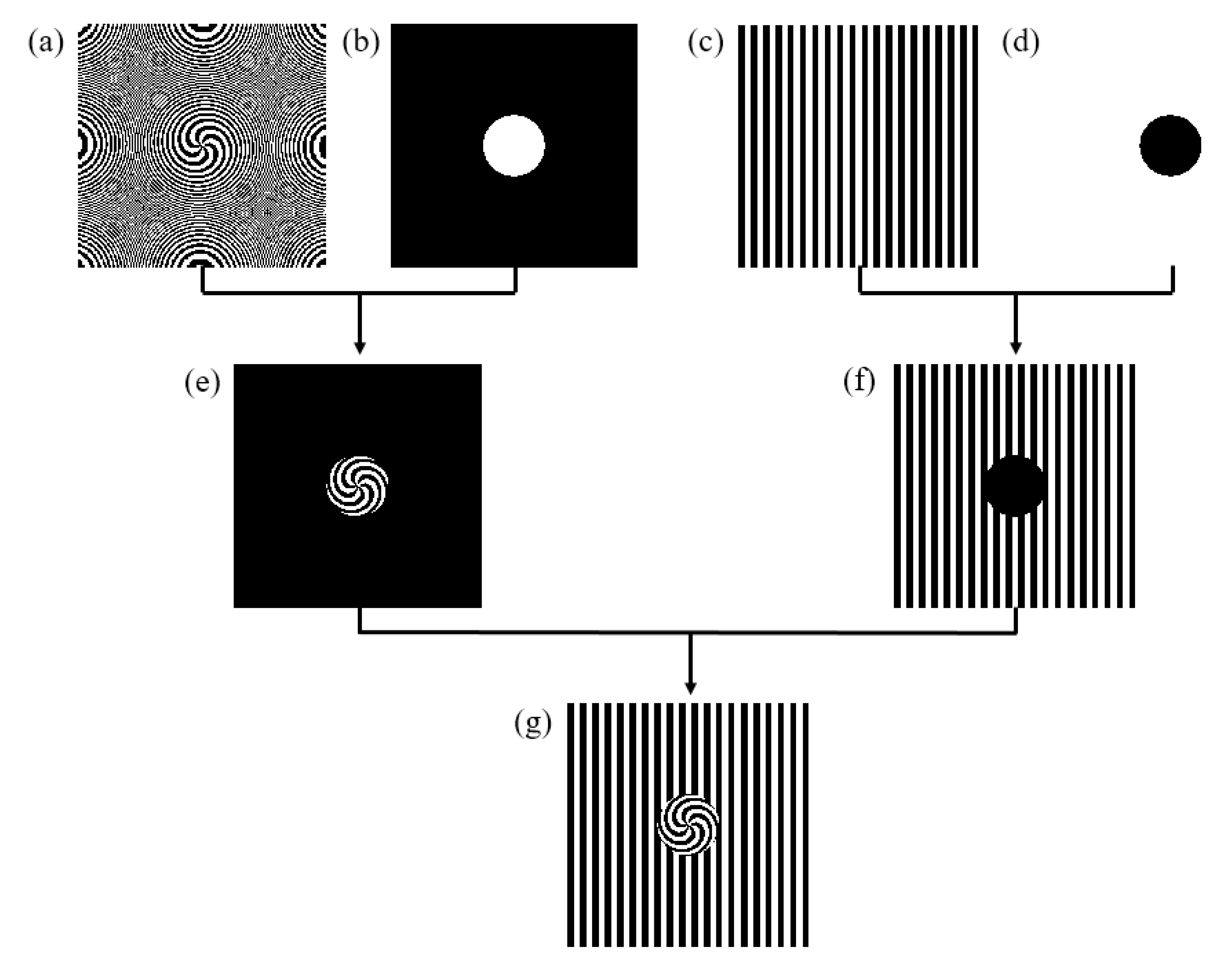
The designing process of the
CSZPG is shown in
Figure 1. The spiral zone plate and the grating with parameters of
f = 250 mm,
d = 400 μm and
l = 6 are shown in
Figure 1a and
Figure 1c, respectively. The filter with the parameter of
R = 1500 μm is shown in
Figure 1b. The structure shown in
Figure 1d is inversed with the filter in
Figure 1b. The inner spiral zone plate by multiplying the spiral zone plate and the filter in
Figure 1a,b is shown in
Figure 1e. The outer grating by multiplying the grating and the inverse filter in
Figure 1c,d is shown
Figure 1f. The designed
CSZPG composed by the inner spiral zone plate and the outer grating is shown in
Figure 1g.
3. Properties of the CSZPG
When a plane wave illuminates the proposed
CSZPG, the intensity distribution in the observation plane can be written as:
where
and
are the coordinates of the observation plane and the
CSZPG plane, respectively,
z is the propagating distance from the
CSZPG to the observation plane.
In order to compute quickly in the simulation, a fast Fourier transform (FFT) method is used to calculate the intensity distribution. So, Equation (7) can be rewritten as:
where
F represents the FFT,
F−1 denotes an inverse FFT.
In the simulations, the
CSZPG is composed by the inner spiral zone plate and the outer grating with
l = 6,
f = 250 mm and
d = 400 μm. The parameter
R of the filter is 1500 μm.
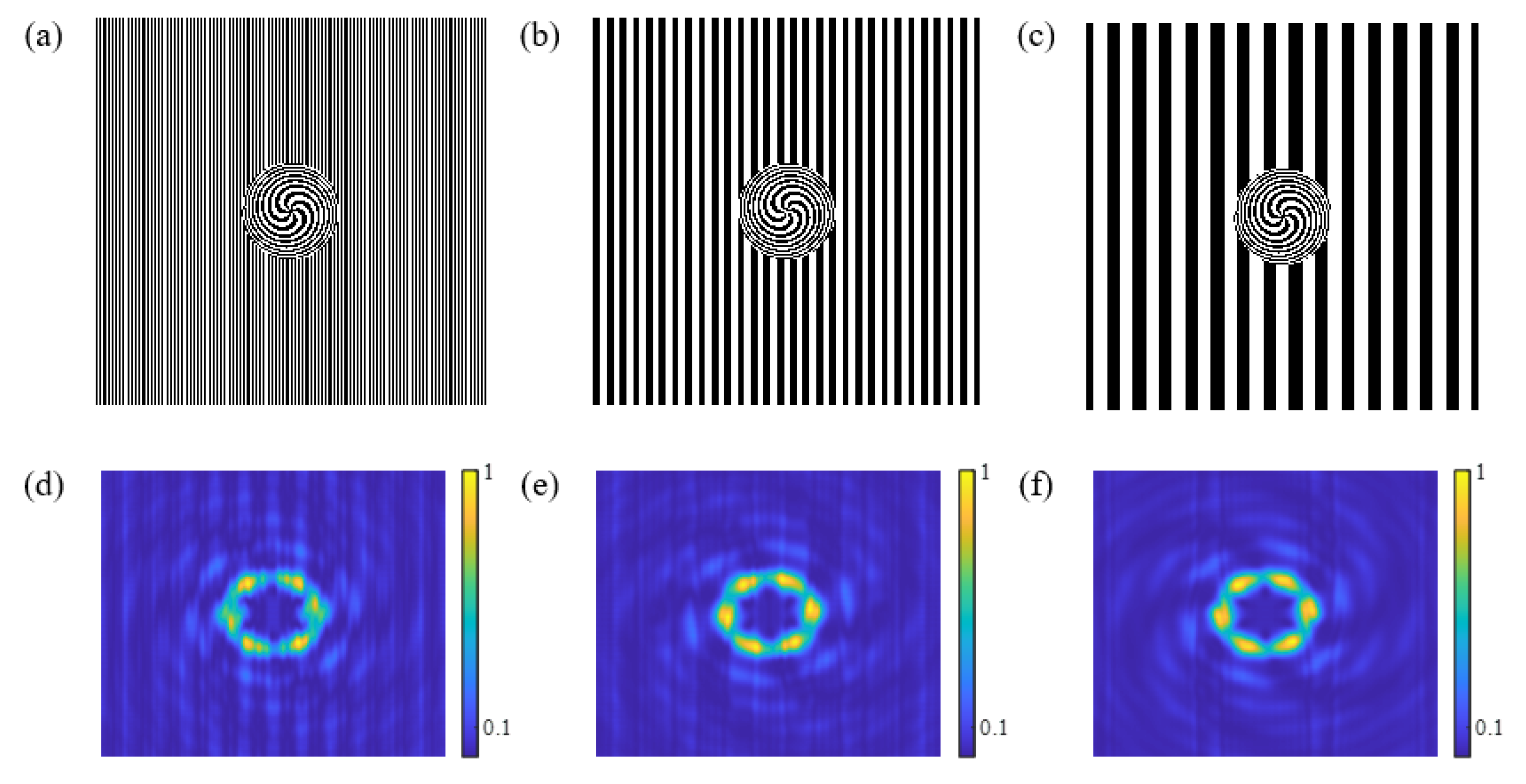
Figure 2a–c show the schematic diagrams of the grating, the
SZP and the proposed
CSZPG, respectively. The diffraction patterns of the grating, the
SZP and the
CSZPG at the location of
z = 250 mm are shown in
Figure 2d–f, respectively. It can be seen from
Figure 2d,e that the grating can generate multiple diffraction orders and the
SZP can generate optical vortex at the location of
z = 250 mm. While the proposed
CSZPG can generate flower mode vortices with six approximately equicohesive petals at the same position of
z = 250 mm, and the number of petals in the flower mode vortices is the same with the topological charge
l of the
SZP. In addition, the normalized intensity distributions along the red lines in
Figure 2e,f are shown in
Figure 3 for comparison. Obviously, the intensity distributions of the
SZP and the
CSZPG have some differences. The vortex size of the
CSZPG is larger than that of the
SZP, and high-order diffractions can clearly be seen in the observed plane. The main reason is that the
CSZPG combines the advantages of the grating and the
SZP, which makes the
CSZPG simultaneously possess the capability of dispersion and focus. Thus, the intensity profile of the CSZPG can be obtained from the focused spot in the
SZP to the flower mode vortices.
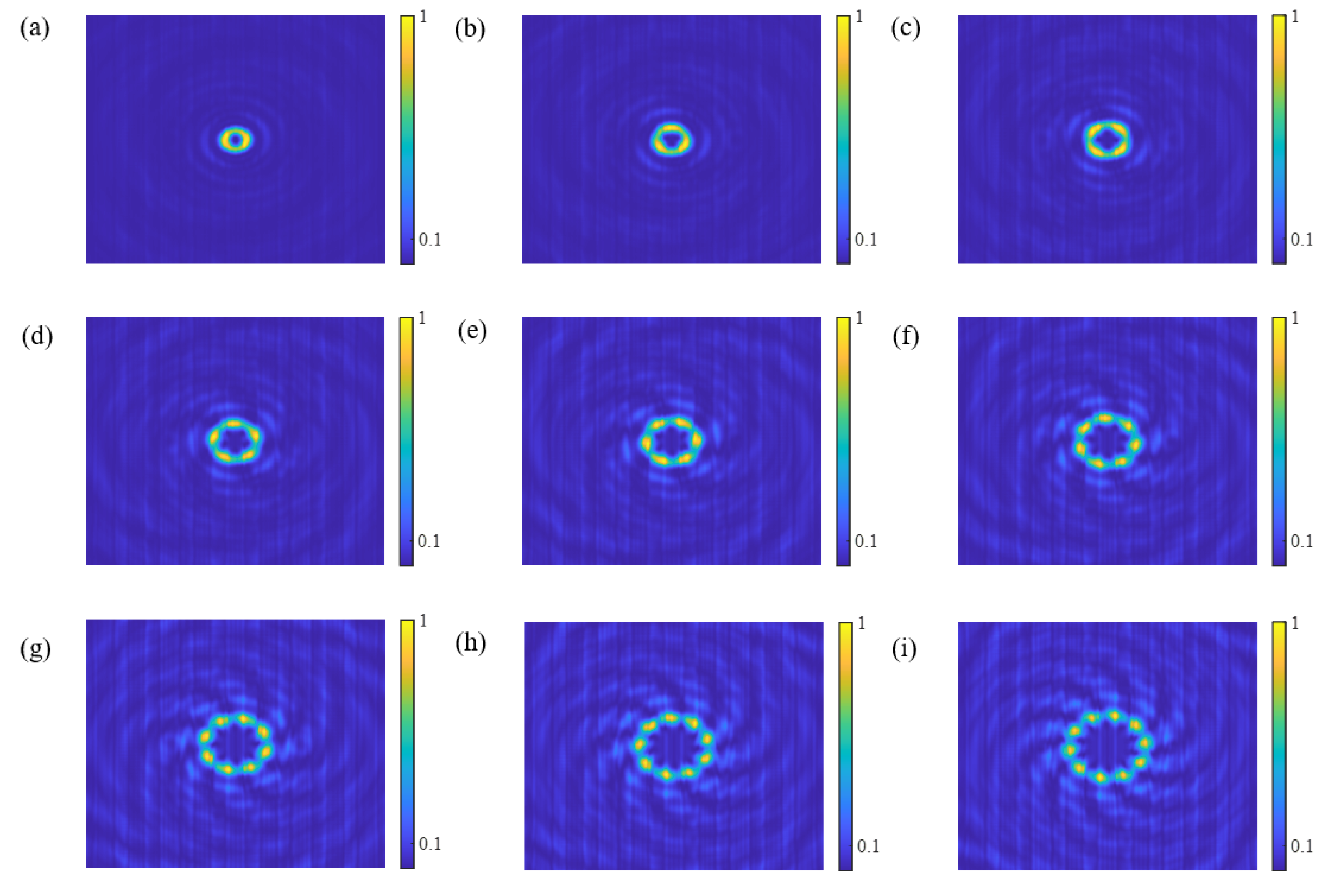
Figure 4a–i show the transverse diffraction patterns of the propagating
CSZPG beams at the location of
z = 250 mm with topological charge
l = 2, 3, 4, 5, 6, 7, 8, 9 and 10, respectively. It can be clearly seen that the
CSZPG generates flower mode vortices with 2, 3, 4, 5, 6, 7, 8, 9 and 10 petals which is same with the topological charge. Since the radius of the vortex increases as the topological charge increases in the
SZP [
28], the
CSZPG composed by the inner
SZP and the outer grating also follows this principle, and the region of the flower mode vortices gradually increases with the increase in the topological charge. Additionally, the spiral directions outside the central petal are reversed when the TCs are different signs in
Figure 5, but the flower mode vortices are approximately the same. Thus, the
CSZPG composed by the inner
SZP and the outer grating can generate flower mode vortices, and the number of petals coincides with the topological charge of the corresponding
SZP.
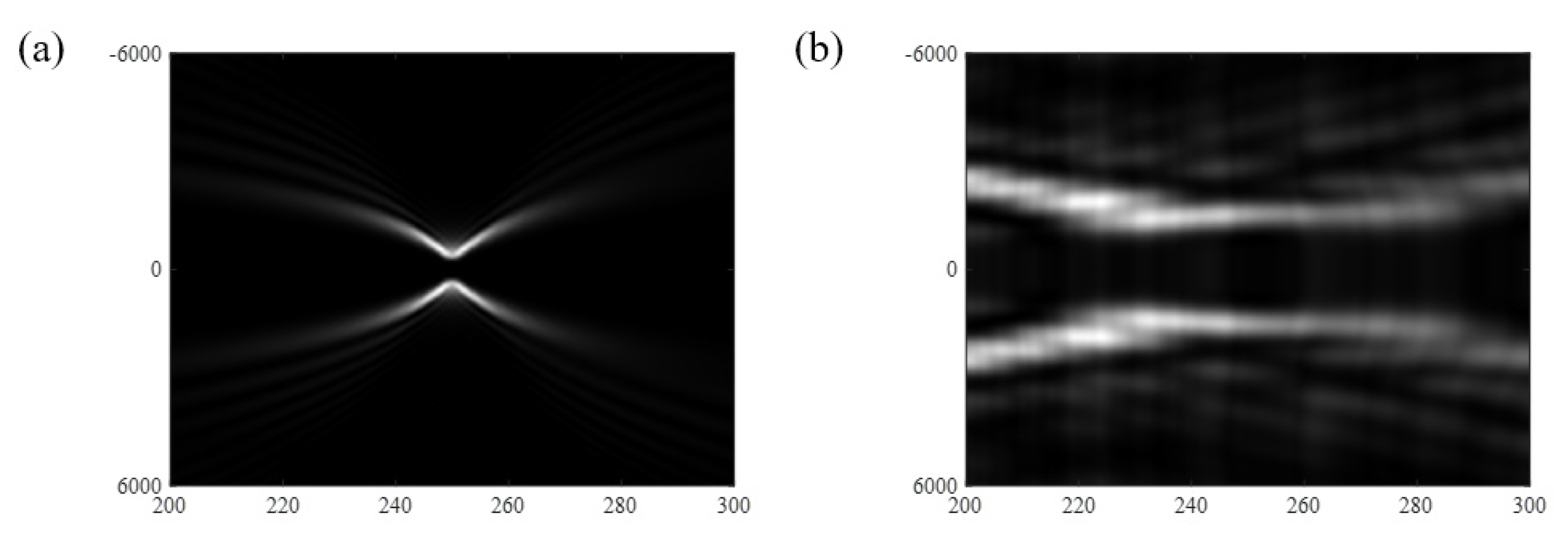
Due to further research studies, it is indicated that the
CSZPG can not only generate flower mode vortices, but that it also has an ultra-long depth of focus. We selected cross-section patterns of the vortex along the propagating direction, and the propagating distance is from 200 mm to 300 mm.
Figure 6a,b show the cross-section patterns of the propagating
SZP and the
CSZPG, respectively. The horizontal axis represents the propagating distance, and the vertical axis denotes the size of the vortex beams in
Figure 6. It can be found in
Figure 6a that the propagating beam focuses at the location of
z = 250 mm and quickly diverges on both sides of the
SZP. However, in
Figure 6b high-order diffractions exist in the region away from the center of the vortex, and the central focal spots are approximately same at the position from
z = 230 mm to
z = 270 mm for the
CSZPG.
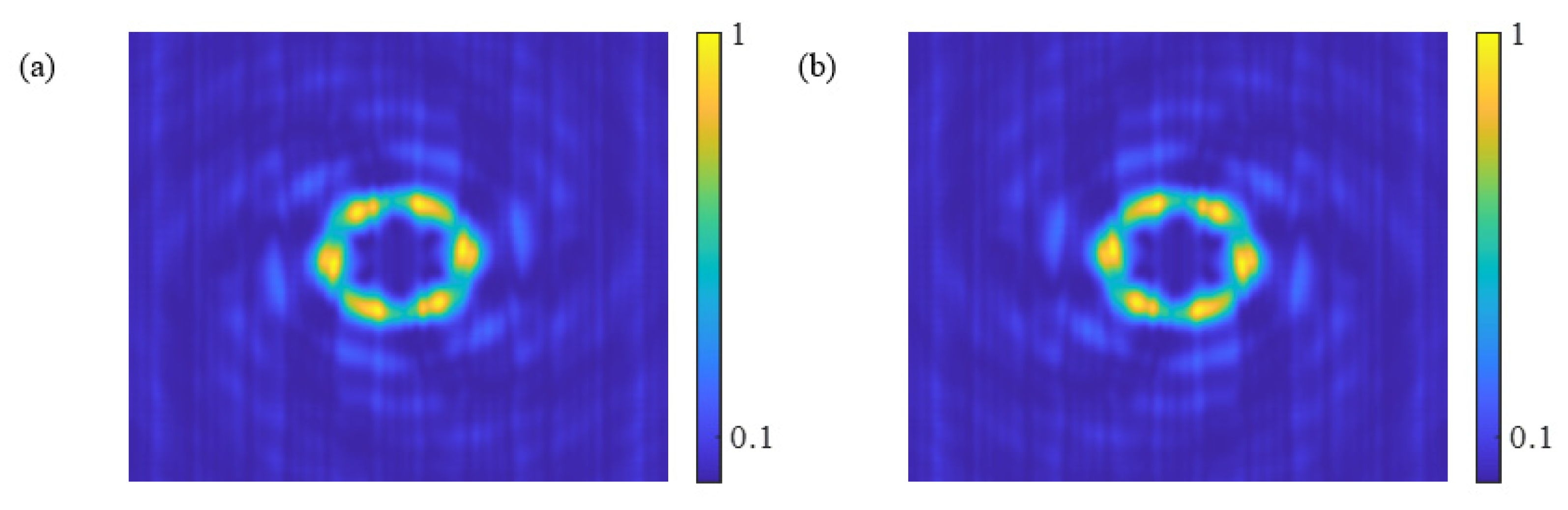
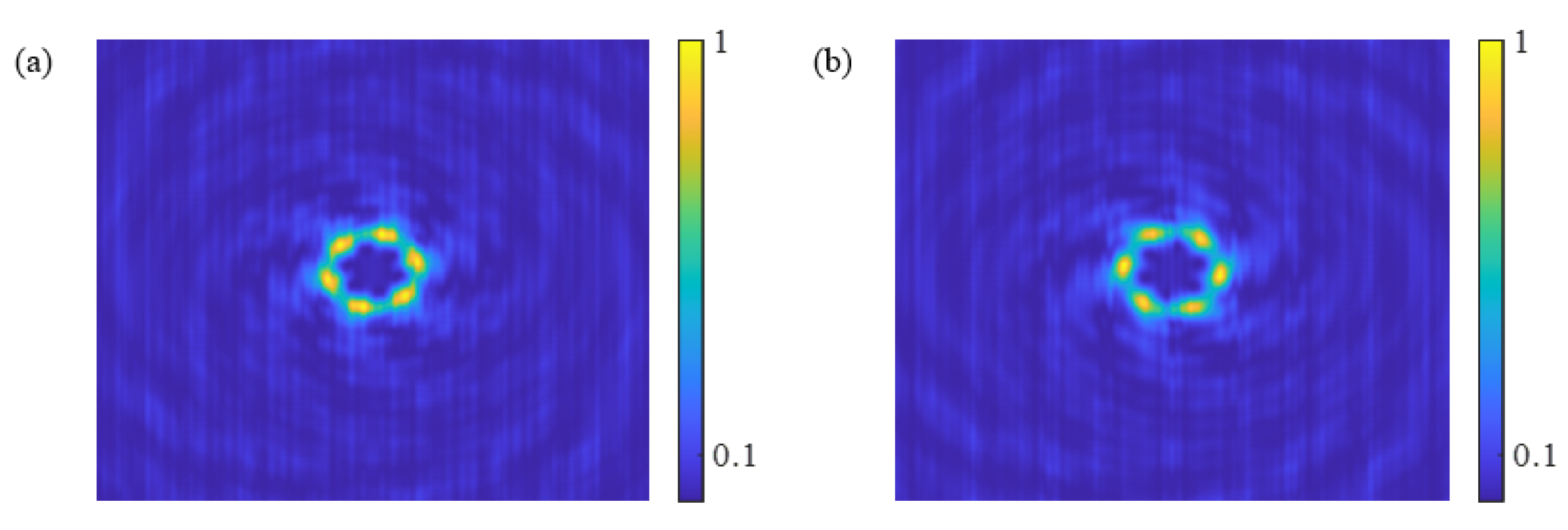
Figure 7a,b show the diffraction patterns for the
CSZPG at the positions of
z = 230 mm and
z = 270 mm, respectively. It can be found that the two patterns have the same size and image approximately. Therefore, compared with the
SZP, the
CSZPG has longer focal depths.
The focusing performance of the CSZPG composed by the inner SZP and the outer grating is determined by the parameters with period, radius, topological charge and focal length. In the following, we will investigate the effect of structural parameters on the focusing performance of the proposed samples.
Figure 8a–c show the schematic diagrams of three
CSZPGs with
d = 100 μm, 400 μm and 800 μm, respectively.
Figure 8d–f show the simulated normalized intensity profiles of the propagating
CSZPG beams corresponding to
Figure 8a–c, respectively. It can be found that the intensity of the vortex is proportional to the period compared with the patterns in
Figure 8d,e. We can attribute this phenomenon to the fact that the dispersion ability of the grating becomes weaker corresponding to the increase in the period, which makes the diffraction intensity concentrate in the region of the vortex. However, when the period is very large, such as 800 μm, the dispersion of the grating is extremely weak, and the intensity profiles are approximately same as those seen in
Figure 8e,f.
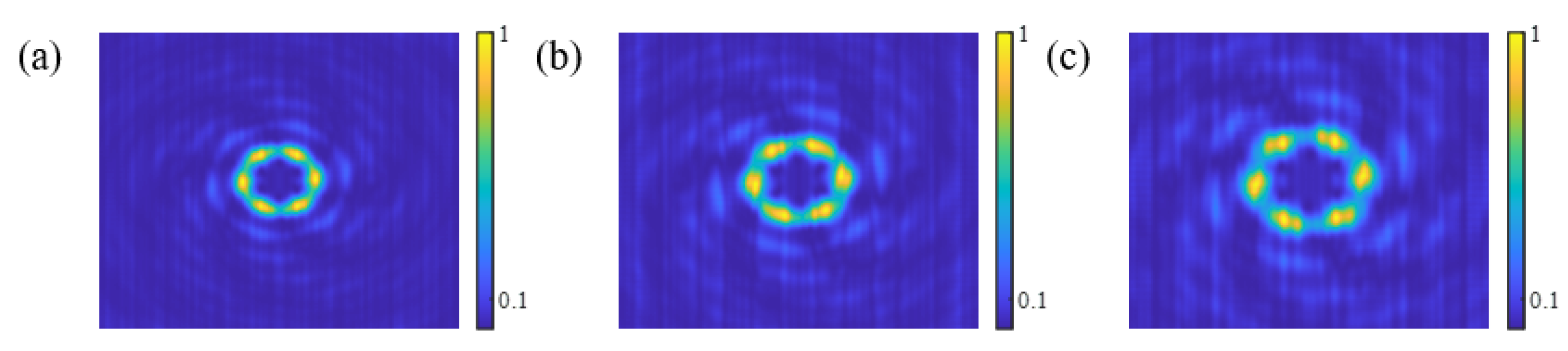
Focal length of the
CSZPG determines the focused position, and the intensity distribution in different focal lengths has some differences. For example,
Figure 9a–c show the intensity distributions of the
CSZPG by combining the
SZP and the grating with the parameter of
f = 200 mm, 250 mm and 300 mm, respectively. It is clearly seen that the intensity profiles of three
CSZPGs are different. As the focal length increases from 200 mm to 300 mm, the vortex size also gradually increases. The main reason is that the dispersion characteristic of the grating exists in the
CSZPG. The distance between different grating orders increases along the direction of propagation. So, for the
CSZPG with the bigger focal length, the vortex size will be larger in the observed plane.
The radius of the filter determines the proportion of the
SZP in the
CSZPG, which affects focusing performance.
Figure 10a–c show the schematic diagrams of three
CSZPGs with
R = 1000 μm, 1500 μm and 3000 μm, respectively.
Figure 10d–f show the transverse diffraction patterns of the propagating
CSZPG beams corresponding to
Figure 10a–c, respectively. In
Figure 10, the
CSZPG can generate flower mode vortices with approximately equicohesive petals. Moreover, it should be noted that the focusing characteristic changes corresponding to the increase in the radius. In
Figure 10d, we can clearly see the flower mode vortices with scattered petals, and the intensity is not concentrated in the focal area but distributed over the whole area. As the radius increases to 1500 μm, the flower mode vortices with six centralized petals can be observed in the focal area and the intensity is mainly concentrated in the focal area in
Figure 10e. While the radius is 3000 μm, six centralized petals of the flower mode vortices merge into a whole in
Figure 10f. Thus, as the radius becomes larger, the area of the
SZP is also increasing in the
CSZPG, which leads the transmittance function of the
SZP playing a major role in the transmittance function of the
CSZPG. As a result, the vortex with scattered petals is constantly merged and finally the intensity pattern is approximately the same as the intensity profile of the
SZP in
Figure 2e.
4. Experiments
In order to prove the result in the simulations, the
CSZPGs with TC of 2, 4, 6, 8, 10 and 12 were fabricated and tested. The parameters of the
CSZPG are set as λ = 632.8 nm,
d = 400 μm,
R = 1500 μm and
f = 250 mm. The fabrication procedure started with patterning the binary
CSZPG onto the photoresist by using the direct writing laser lithography technology. After that, we used the wet etching to transfer the fabricated pattern onto the chrome layer and remove the residual photoresist with organic solution. Finally, the
CSZPG was rinsed and dried.
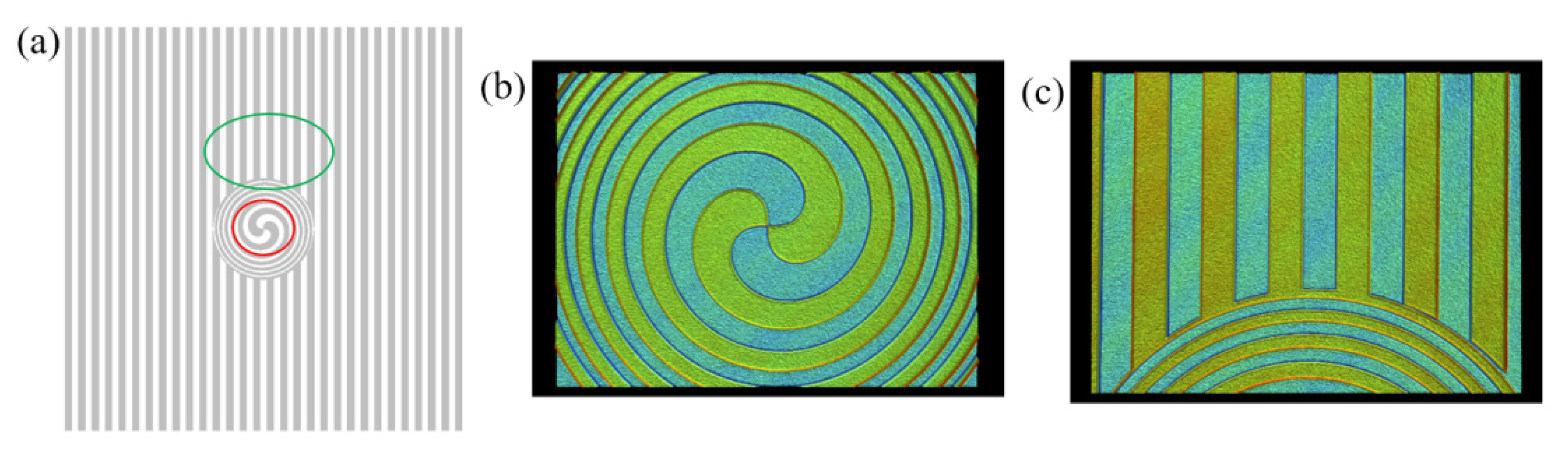
Figure 11b,c show the contourgraph images of the fabricated
CSZPG corresponding to the red and blue circles shown in
Figure 11a, respectively. The observed binary
CSZPG reveals that the pattern of simulation design is in good agreement with those of actual fabrication, and the designed
CSZPG has strong process compatibility.
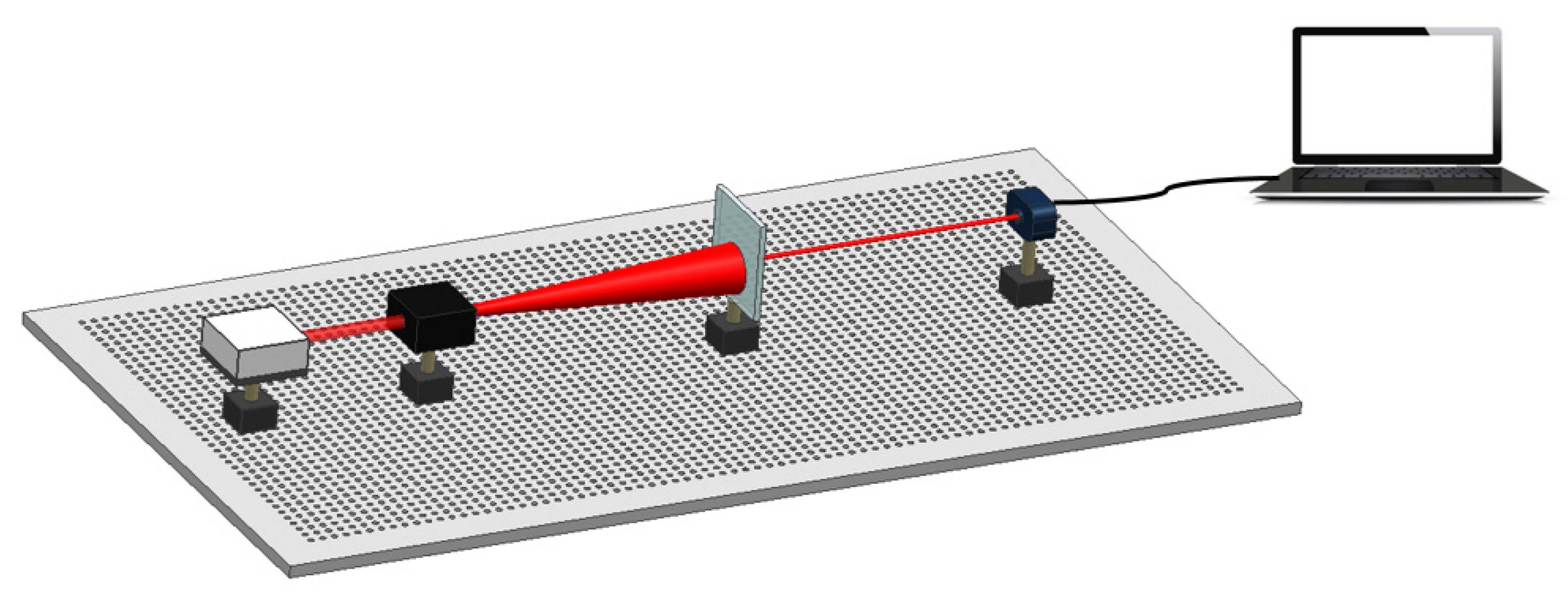
The fabricated
CSZPG was characterized by using the designed experimental setup demonstrated in
Figure 12. Linearly polarized light with
λ = 632.8 nm passed through the beam expander to increase the area of the beam. Then, the beam illuminated the fabricated
CSZPG. The far-field diffraction pattern from the
CSZPG was recorded by a charge coupled device (CCD, Lumenera LW230) with 1600 × 1200 pixels and 4.4 μm pixel size.
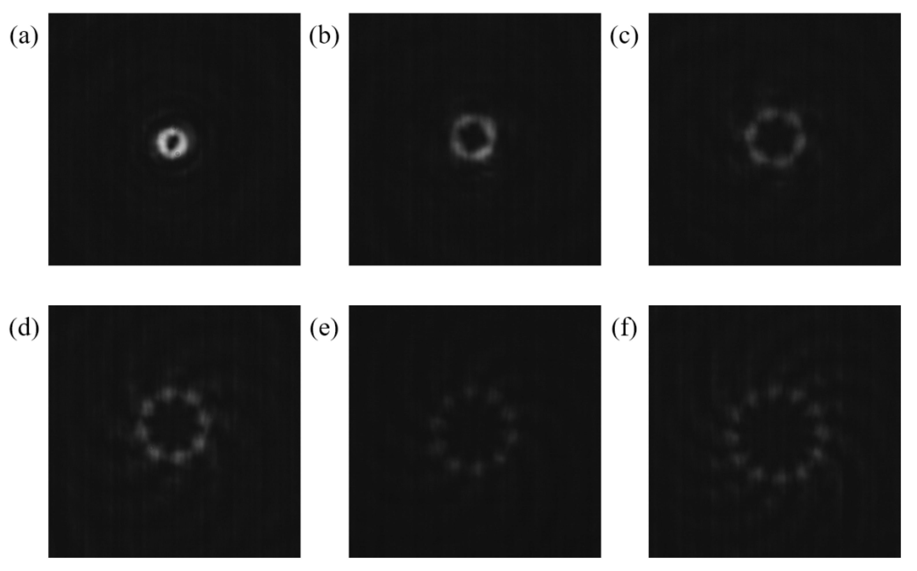
As expected, it is experimentally demonstrated that in
Figure 13a–f the
CSZPG can generate flower mode vortices with approximately equicohesive petals, and the number of the petals is 2, 4, 6, 8, 10 and 12, which are equal to the topological charges, respectively. Moreover, the captured patterns are approximately the same as the corresponding numerical patterns in
Figure 4. It should be noted that the intensity of the generated flower mode vortices becomes weaker as the topological charge increases. The main reason is that the
CSZPG composed by the
SZP and the grating possess the capability of dispersion, which makes the total light intensity evenly distribute over each petal. So, with the increase in topological charge, the intensity of the single petal gradually decreases.
Finally, we research the diffraction patterns of the design element away from the focal length. So, we measured the images of the
CSZPG located at the positions of
z = 230 mm, 250 mm and 270 mm in
Figure 14b–d, respectively. It can be seen that the intensity and the size of the flower mode vortices generated by fabricated
CSZPG at different positions are approximately the same. In addition, the shapes of the beams are well preserved at the positions of
z = 220 mm and 290 mm in
Figure 14a,e. Thus, the experiments show that
CSZPG can achieve the long focal depths.
