Article

Low-Complexity Sampling Frequency Offset Estimation and Compensation Scheme for OFDM-Based UWOC System

Key Laboratory of Specialty Fiber Optics and Optical Access Networks, Joint International Research Laboratory of Specialty Fiber Optics and Advanced Communication, Shanghai University, Shanghai 200444, China
*
Author to whom correspondence should be addressed.
Photonics 2022, 9(4), 216; https://doi.org/10.3390/photonics9040216
Submission received: 16 February 2022 / Revised: 23 March 2022 / Accepted: 23 March 2022 / Published: 25 March 2022
(This article belongs to the Special Issue Visible Light Communication (VLC))

Abstract

:
In this paper, a simple sampling frequency offset (SFO) estimation and compensation scheme based on two phase-conjugated pilots is proposed and experimentally demonstrated in an OFDM-based underwater wireless optical communication (UWOC) system. The phase shift is obtained by simple multiplication for phase-conjugated pilots, and the results are averaged to perform more accurate phase estimation. The experimental results show that the estimation offset is limited within ±3 ppm when the SFO ranges from −1000 ppm to +1000 ppm over a 1 m tap water channel. Moreover, with the help of the proposed scheme, up to ±300 ppm SFO can be well-compensated with error vector magnitude (EVM) penalties below 1 dB after 1 m underwater transmission. In addition, the results demonstrate that, compared with the ideal case without SFO, our proposed SFO compensation scheme can provide nearly negligible bit error rate (BER) penalties in saltwater with the highly scattering property.

1. Introduction

In recent years, underwater wireless optical communication (UWOC) has been considered a promising technology for future underwater high-speed data transmission [1,2,3]. Compared with underwater acoustic or radio frequency (RF) communication systems that exhibit either low bandwidth or high attenuation, UWOC can offer a large bandwidth with low propagation loss [4,5]. Because blue-green (400–550 nm) visible light fits within the low absorption window of seawater, blue-green LD/LED-based UWOC can achieve relatively long-distance and high-speed underwater communication at the same time and is expected to play a significant role in various ocean applications [6,7]. Since LD/LED has the fast-switching feature for amplitude modulation, intensity modulation with direct detection (IMDD) is usually applied in a cost-effective UWOC system [8]. To improve the spectral efficiency (SE) of high-speed UWOC systems, orthogonal frequency division multiplexing (OFDM) with high SE and flexible bandwidth has attracted much attention [9,10,11].
However, one disadvantage of OFDM is its sensitivity to frequency offset [12,13]. Although carrier frequency offset (CFO) does not exist in the real-valued IMDD OFDM systems, sampling frequency offset (SFO) between transceivers inevitably exists due to the clock mismatch of DAC and ADC [14]. Since the transceivers are physically separated, a standard ±200 ppm SFO should be compensated for practical optical transmission systems [15]. Generally, the effects of SFO on received OFDM signals are marked by amplitude attenuation, subcarrier phase rotation, inter-symbol interference (ISI) and inter-carrier interference (ICI) [15,16]. These will seriously deteriorate the system performance. Fortunately, the amplitude attenuation can be compensated for by channel equalization, and the ICI can be regarded as additional noise when the SFO is small. If the number of data-carrying OFDM symbols in each OFDM frame is appropriate and the optimal cyclic prefix/suffix (CP/CS) per OFDM symbol is chosen [16], the SFO-induced ISI can also be avoided. Therefore, the SFO compensation is mainly to correct the SFO-induced subcarrier phase rotation [17].
Several methods have been intensively investigated for SFO estimation and compensation, which can be categorized into the following two types. One is the hardware scheme [18,19], which realizes sampling clock frequency synchronization by adjusting the voltage-controlled oscillator with feedback/feedforward information. This requires high-precision, stable voltage-controlled oscillators and additional analog circuits. Another way of mitigating the SFO effect is digital signal processing (DSP). Depending on the utilization of assistant information, it can also be divided into blind and data-aided estimation methods. An overhead-free SFO compensation scheme based on inter symbol differential detection (ISDD) is proposed in [20,21]. However, this method will cause residual phase noise. Then, the fourth-power algorithm is used for SFO estimation in [22,23]. The application of the method is limited since it is suitable for the OFDM symbols with phases of ±π/4 or ±3π/4. The data-aided methods estimate the SFO by using the pilot or training sequence (TS). Then the SFO compensation is completed in time or frequency domain [24,25,26,27,28,29,30]. The fourth-order piecewise polynomial interpolation is the most popular time-domain compensation method [24,25], which can alleviate ICI at the expense of additional DSP computing resources. The pilot-aided SFO estimation method can compensate up to ±1000 ppm SFO by correcting the SFO-induced phase rotation in the frequency domain [26,27]. It is noteworthy that the methods will inevitably reduce SE. In [28,29,30], the SFO estimation and compensation scheme based on TSs is proposed. The TSs can also be used for synchronization and channel estimation, which improve the SE. Nevertheless, the rigorous OFDM structure limits the compensation range of SFO to less than ±200 ppm.
In this brief, to balance the compensation range and spectral efficiency, a simple pilot-aided SFO estimation and compensation scheme is proposed. The SFO compensation performance is experimentally investigated in an LD-based UWOC link with a 3-dB bandwidth of approximately 5.36 MHz. The main contributions of this literature can be summarized as follows:
(1)
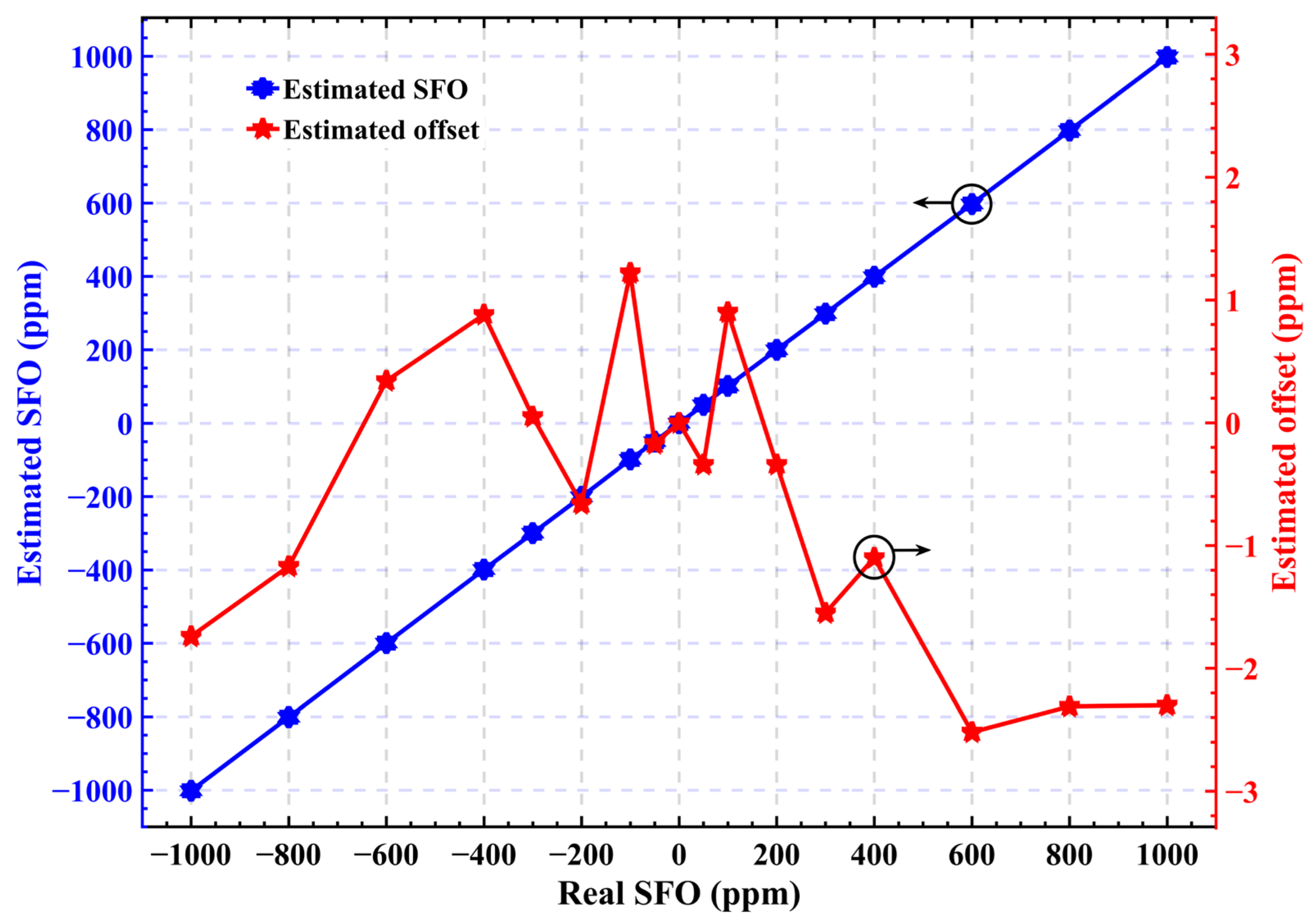
High accuracy and wide SFO compensation range. Up to ±1000 ppm SFO can be well-estimated with an accuracy of less than ±3 ppm after 1 m underwater transmission. Moreover, an estimation deviation within ±2 ppm can be achieved for the SFO below ±400 ppm;
(2)
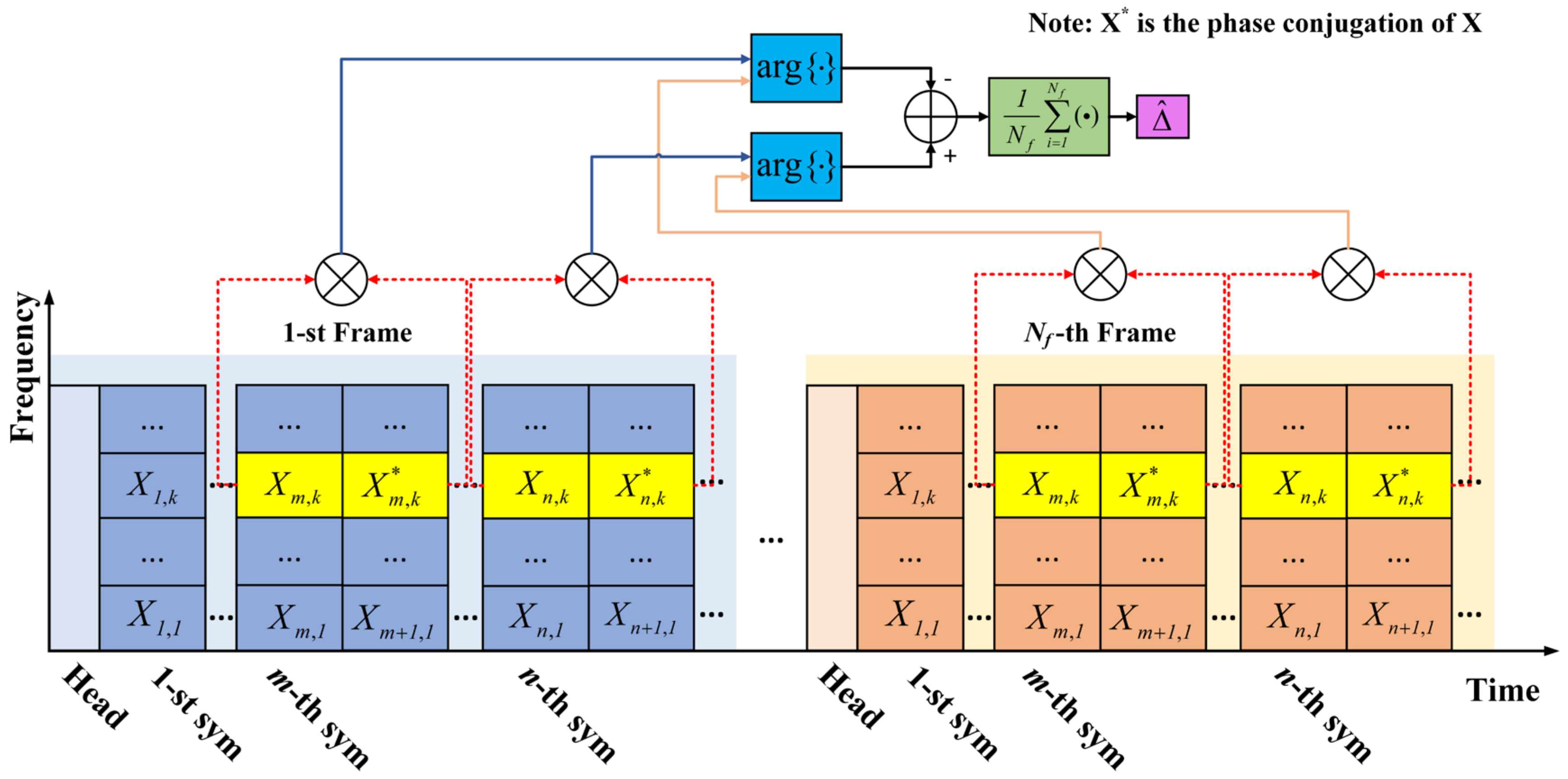
Low computational complexity. Unlike traditional pilot-aided schemes utilizing the least square (LS) method to fit the SFO slope curve, the proposed scheme utilizes two phase-conjugated pilots for SFO estimation in each OFDM frame and an averaging processor is designed to improve estimation accuracy. These cause the decrease in operational complexity.

2. The Principle of SFO Estimation and Compensation

The OFDM frame consists of one frame head and multiple data-carrying OFDM symbols. The frame head is composed of several training sequences. As illustrated in Figure 1, we assume that the phase-conjugated pilots are inserted after the m-th symbol and the n-th symbol on the k-th subcarrier. On the receiver side, the training sequences are used for symbol synchronization and channel estimation. When the system works in an asynchronous way, the m-th OFDM symbol of the k-th subcarrier in the frequency domain can be approximately written as:
R m , k = S m , k × H k e j ϕ m , k + W m , k , k = 0 , 1 , 2 , , N 1
where S m , k and R m , k are the transmitted and received frequency domain signal on the m-th OFDM symbol of the k-th subcarrier, H k is the channel response on the k-th subcarrier, W m , k represents the noise, ϕ m , k = 2 π m k N T Δ / N is the SFO-induced phase rotation for the m-th OFDM symbol of the k-th subcarrier, N is the FFT size, N T is the length of the OFDM symbol including CP, the SFO between transmitter and receiver is denoted by Δ = ( f t f r ) / f r , f t and f r represent the sampling frequency in the DAC and ADC, respectively.
After zero-forcing equalization, the equalized signal is expressed as:
R ^ m , k = S m , k e j ( ϕ m , k + θ k ) + W m , k
where θ k is the common phase error caused by inaccurate channel estimation. The OFDM symbols from the same subcarrier index are generally considered to have the same common phase error θ k [22]. Thus, the product of a pair of phase-conjugated OFDM symbols is followed as:
R ^ m , k × R ^ m + 1 , k = | S m , k | 2 e j ( ϕ m , k + ϕ m + 1 , k + 2 θ k ) + N m , k
where N m , k can be considered as additive noise.
Then, the superposition value of phase rotation on the phase-conjugated symbols can be given by:
φ ^ m , k = a r g { R ^ m , k × R ^ m + 1 , k } = 2 π N T k Δ ( 2 m + 1 ) / N + 2 θ k + ω k
where a r g { } stands for the angle operation, ω k represents the phase noise. As shown in Figure 1, a subtraction operation is performed to suppress the common phase error θ k , the difference of superposition values between two groups of phase-conjugated symbols in the i-th OFDM frame can be expressed as:
φ ^ i , k = φ ^ n , k φ ^ m , k = 4 π N T k × ( n m ) Δ / N + ω k
To further reduce the influence of the enhanced phase noise ω k and improve the estimation precision, the phase difference φ ^ k is obtained by the averaging processor of N f OFDM frames and can be expressed by:
φ ^ k = 1 N f i = 1 N f φ ^ i , k
In this way, the SFO can be accurately estimated as follows:
Δ ^ = φ ^ k × N / ( 4 π N T k × ( n m ) )
Finally, the m-th OFDM symbol on the k-th subcarrier should be multiplied by a compensation factor e x p ( j 2 π k m N T Δ ^ / N ) to correct the SFO-induced subcarrier phase rotation.

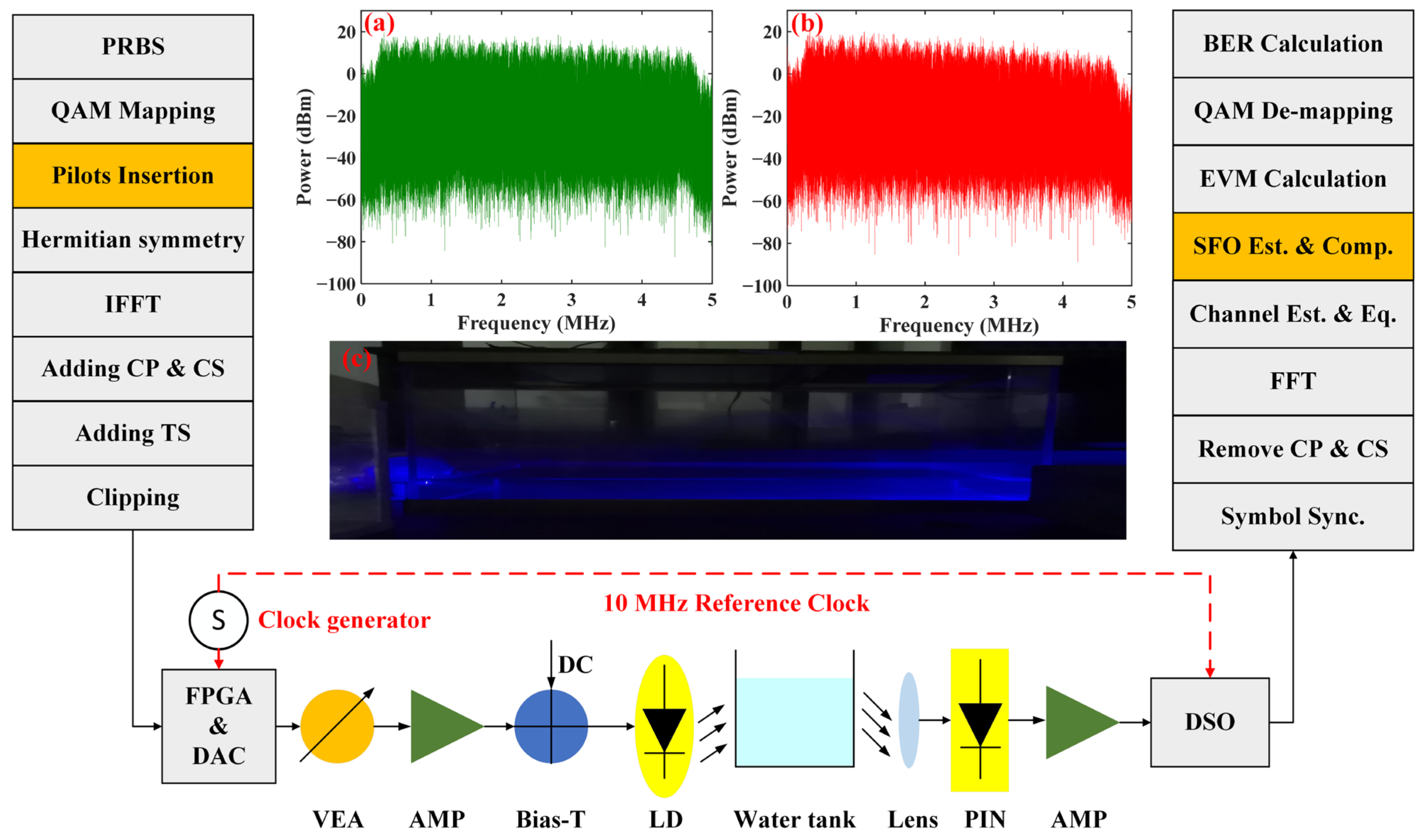
3. Experimental Setup

The experimental setup of the UWOC system based on direct current-biased optical OFDM (DCO-OFDM) is established and demonstrated in Figure 2. The key parameters of the system are listed in Table 1. On the transmitter side, the digital OFDM signal is generated offline with DSP algorithms in MATLAB. Firstly, the generated pseudo-random binary sequence (PRBS) of 217 − 1 is mapped into m-QAM symbols and two phase-conjugated pilots are inserted for SFO estimation. Then, Hermitian symmetry and inverse fast Fourier transform (IFFT) guarantee real signal transmission. The CP and CS are added for each OFDM symbol, and two training sequences (TSs) are added to realize symbol synchronization and channel equalization. Subsequently, the generated digital OFDM signal is loaded into the ROM of a Xilinx AX545 FPGA board and sampled by an 8-bit DAC (AD9280) with a 10 MS/s sampling rate. A variable electrical attenuator (VEA) is added to adjust the amplitude of the OFDM signal. The output analog signal is boosted by an electrical amplifier (AMP-OPA657) and is combined with direct current (DC) bias via a Bias-Tee to drive the blue LD (OSRAM, PL 450B), which can convert an electrical signal into an optical signal for underwater transmission.
On the receiver side, according to the divergence angle of LD and the attenuation coefficient of tap water in [31], the estimated receiving optical power after 1 m underwater transmission is approximately −22.59 dBm. To further improve the receiving optical power, the output beam is concentrated through the convex lens and fed into a commercial PIN (Hamamatsu, S10784). Then, the detected electrical signal is amplified by the amplifier (AMP-OPA656) and then captured by a digital storage oscilloscope (KEYSIGHT, DSO-S 804A, America). The DSO collects 5,000,000 sampling points each time for MATLAB offline processing. The main DSP flow sequentially includes symbol synchronization, CP and CS removal, 64-point FFT, channel estimation and equalization, SFO estimation and compensation, EVM calculation, QAM de-mapping and BER calculation. Due to the limitation of the receiving amplifier circuit, the 3 dB bandwidth of the system is 5.36 MHz. To investigate the SFO effect, the DAC and ADC are clocked by the same 10 MHz reference clock, which can avoid the difference between reference clocks. Different SFOs can be obtained by changing the frequency of the external clock source for the DAC.

4. Experimental Results and Discussion

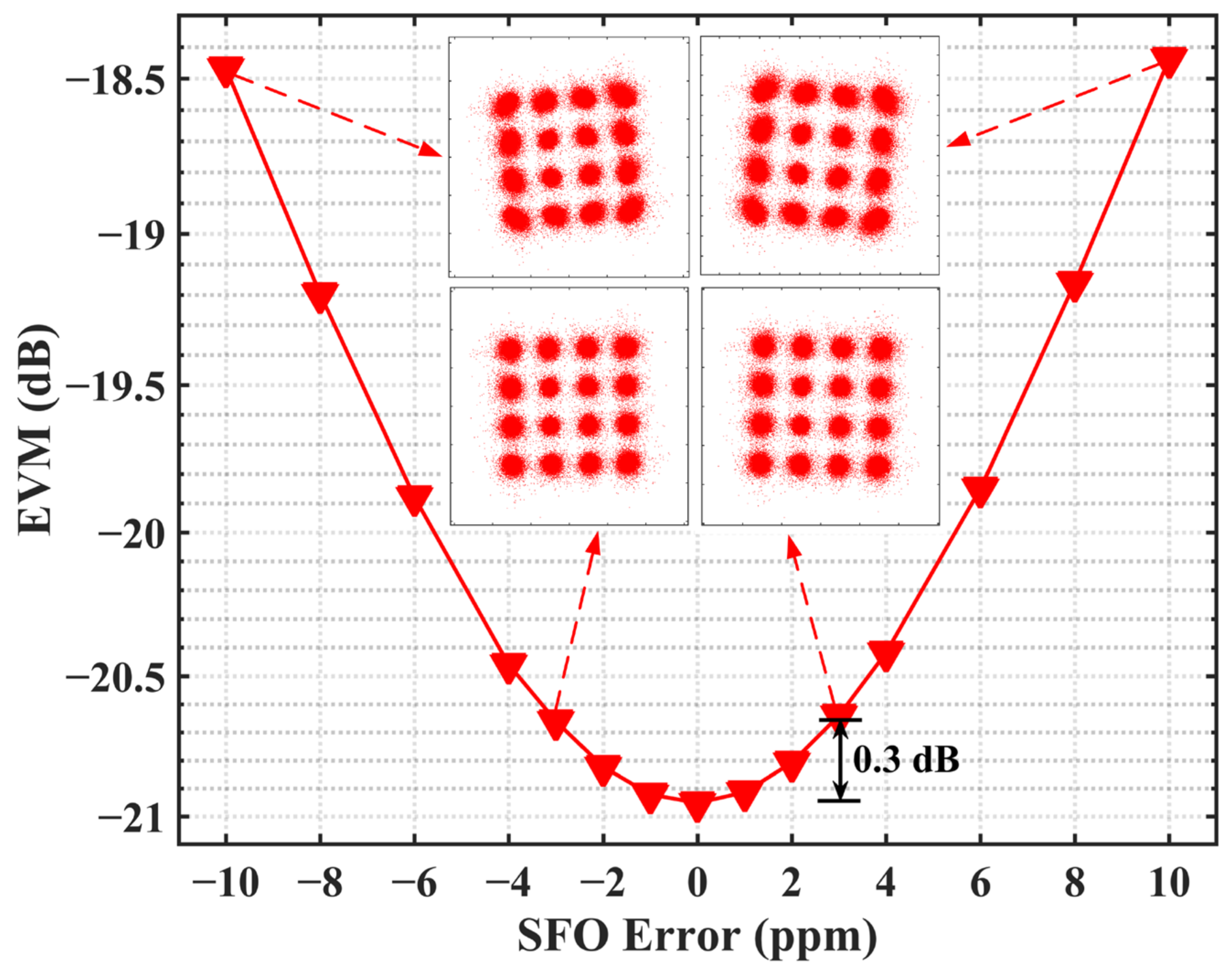
4.1. EVM Penalty in Terms of SFO Error

To investigate the effects of SFO estimation accuracy on EVM performance, we artificially set the SFO from −10 to 10 ppm to simulate the SFO error, and the corresponding experiments are carried out in a 1 m tap water channel. Figure 3 shows the measured EVM performance as a function of the SFO error, where the 16-QAM constellations are inserted when the SFO errors are ±3 ppm and ±10 ppm, respectively. As shown in Figure 3, with the increase in the SFO error, the EVM performance gradually declines. For the SFOs with opposite values, the EVM penalties are essentially the same due to the adding of CP and CS in each OFDM symbol. When the SFO error is up to ±10 ppm, the EVM performance has deteriorated significantly. Compared with the error-free case, the corresponding EVM penalties are approximately 2.5 dB. When the SFO errors are dipped to ±3 ppm, the EVM penalties are only 0.3 dB, and the phase rotations of the constellations are very slight, which has a negligible effect on the system performance. This is also supported by our previous work in real-time optical OFDM systems [32]. Therefore, we can take the estimated offset <±3 ppm as our accuracy target because it has little impact on the system performance.

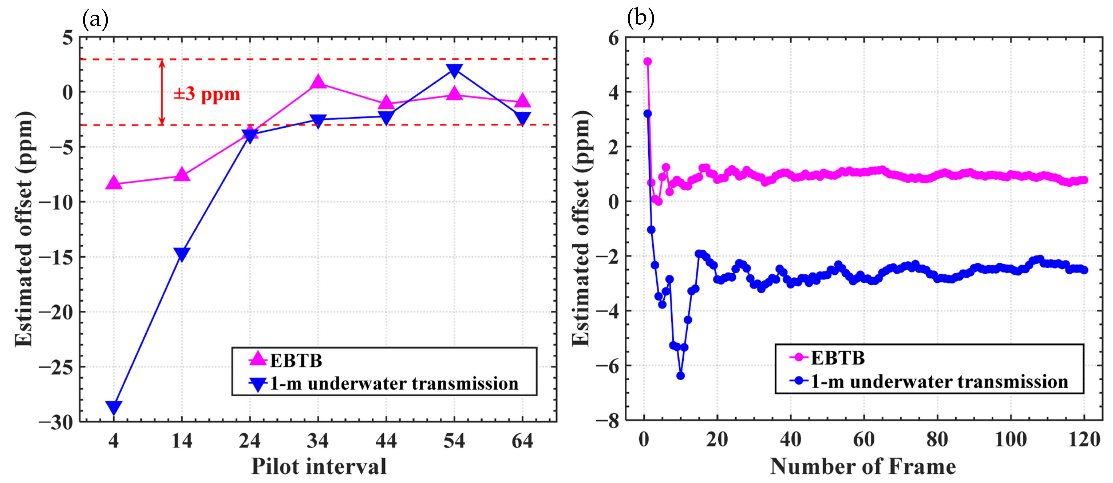
4.2. Influence of Frame Number and Pilot Interval on Estimation Accuracy

In order to further identify the optimal pilot interval and the convergence of multi-frame averaging, the comparison of estimation accuracy is implemented after electric back-to-back (EBTB) and 1 m tap water channel transmission when the SFO is 600 ppm. The pilot interval is defined as n-m in Equation (7). Figure 4a shows the estimated offset obtained from the average result of 120 frames at different pilot intervals. As shown in Figure 4a, when the pilot interval is 4, the estimated offset is too large and the impact of SFO cannot be well-alleviated. The reason is that the phase difference in Equation (5) is small and the estimated SFO value is more vulnerable to noise. Furthermore, the target accuracy can be successfully achieved as the pilot interval is up to 34. In such a case, the curve of estimated offset tends to be flat, and the further increase in the pilot interval will not improve the estimation accuracy. Moreover, since the signal after EBTB transmission is less affected by noise, the estimation accuracy of EBTB is more accurate and the estimated offset is less than ±1 ppm. Figure 4b demonstrates the corresponding estimated offset versus the frame number when the pilot interval is 34. It shows clearly that the SFO estimated offsets can all converge very fast, and the required frame numbers are approximately 40. The fast convergence of SFO estimation can further depress the computational complexity. In the following discussion, the pilot interval is fixed at 34 and the phase-conjugated pilots are inserted on the 22nd subcarrier in each frame. This is because the phase shift of high subcarriers rises faster as the symbol index increases. The large phase difference can achieve more precise estimation accuracy [27].

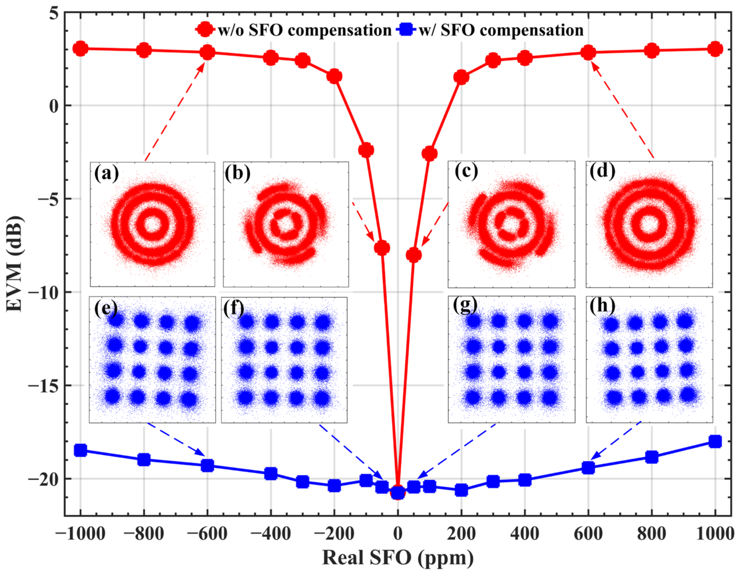
4.3. SFO Estimation Accuracy and Compensation Range

Following the convergence analysis, we investigate the estimation accuracy of the proposed scheme under a wide SFO range. Figure 5 shows the estimated SFO value and offset through a 1 m tap water channel in the IMDD-OFDM system. It can be seen that when the SFO varies from −1000 ppm to +1000 ppm, the estimated SFO values are very close to the real SFO, and the estimated offset is within ±3 ppm. In particular, when the SFO is less than ±400 ppm, an estimation deviation within ±2 ppm can be achieved. The results demonstrate that the proposed SFO estimation technique is capable of achieving high-accuracy SFO estimation in an asynchronous OFDM-based UWOC system.
Figure 6 shows the EVM performance of a system over different SFO after 1 m underwater transmission, where the 16-QAM constellations are also inserted in the presence of ±50 ppm and ±600 ppm SFO. It can be seen that the EVM performance without SFO compensation deteriorates rapidly with the increase in SFO. As shown in Figure 6a–d, the phase rotations can be observed in 16-QAM constellations without SFO compensation, and the constellations are hard to distinguish. In addition, the directions of phase rotation for the negative and positive SFO value are opposite and the rotation angle is proportional to the value of SFO. After using the proposed SFO compensation scheme, the system performance can be significantly improved. From Figure 6e–h, the constellations become much clearer because the phase rotations are corrected with SFO compensation. Compared with the SFO-free case, even if the SFO is up to ±1000 ppm, the EVM penalties after SFO compensation are less than 3 dB. Moreover, when the SFO is less than ±300 ppm, the EVM with compensation is very close to the case without SFO and the EVM penalty is below 1 dB.

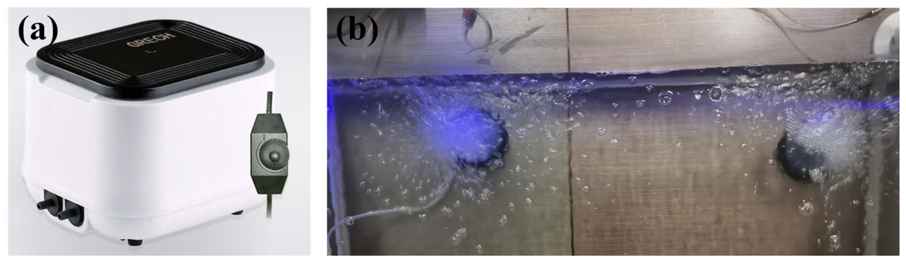
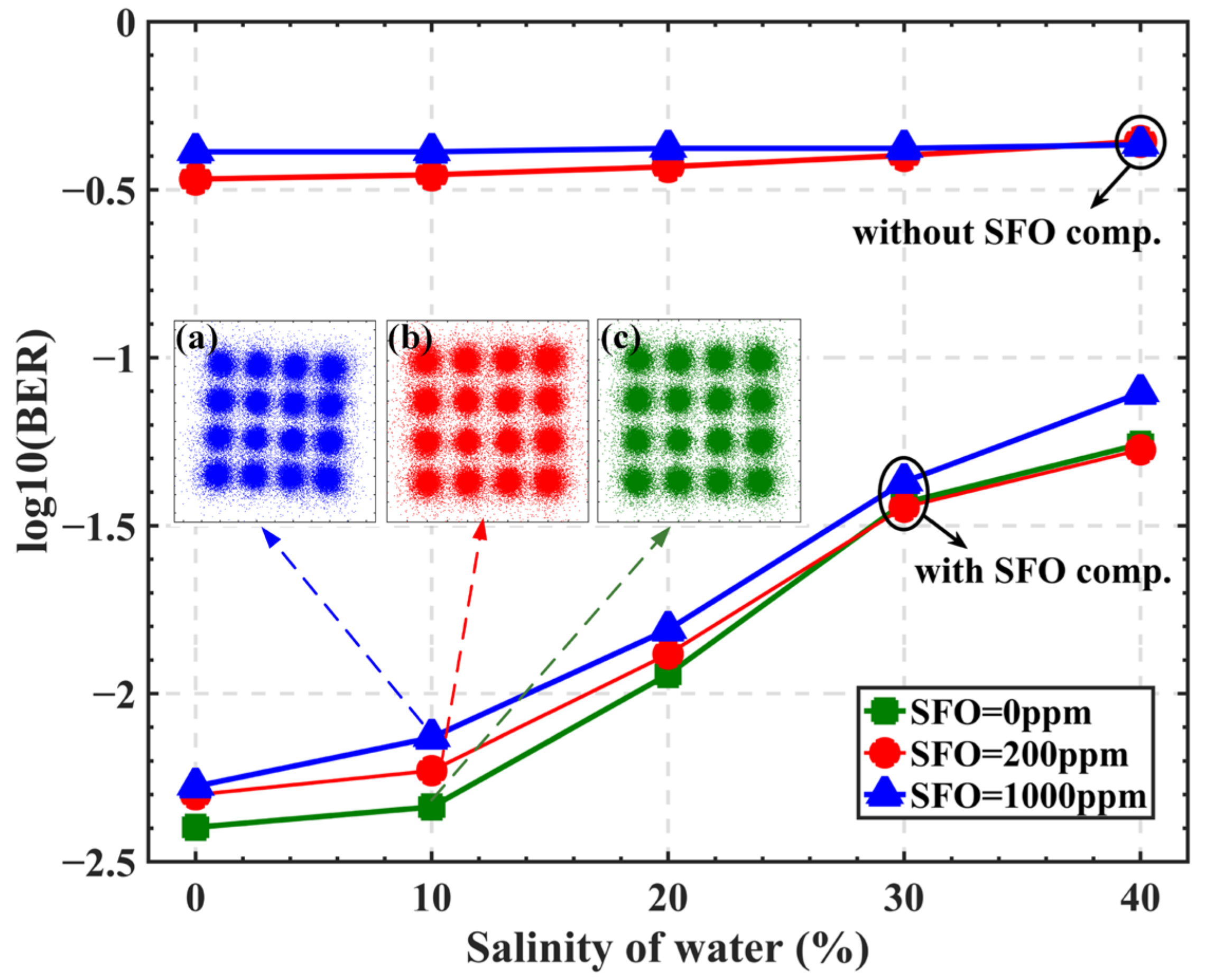
4.4. SFO Compensation Performance in Different Underwater Environments

Broken surface waves and rain produce air bubbles in the ocean. To evaluate the influence of air bubbles on the compensation performance of UWOC, we put the oxygen pump in the water tank to generate the bubbles and disturbances. The physical device diagram is shown in Figure 7. The exhaust volume is set to 16 L/min and the experiments are carried out under a 1 m tap water link. The EVM performance after SFO compensation is shown in Table 2. The results show that the EVM penalties are similar to the cases without bubbles. Compared with the SFO-free case, the EVM at 200 ppm has no loss after compensation. The EVM penalty is 2 dB in the presence of 1000 ppm SFO. It can prove that the air bubbles have little impact on SFO compensation performance, which shows the proposed SFO estimation and compensation method is robust.
Light propagation undergoes serious reduction due to the absorption and scattering in seawater [33]. Therefore, we add sea salt in the 0.5 m link to assess the system performance. Since a longer communication distance always means a lower received optical power and SNR, we move the condenser lens away from the direction perpendicular to the incident light to reduce the SNR of the receiver, which can show the potential of the UWOC system at low SNR or long-distance transmission. The BER performance over the different salinity of water is presented in Figure 8 and the corresponding receiving optical power (ROP) is listed in Table 3. It is worth noting that the transform model of BER and SNR/EVM based on Gaussian noise is still applicable in the underwater channel [11]. It can be found that the concentrations of sea salt-added water are dominated for the signal degradation when the SFO is 0 ppm. With the increase in salinity, the signal attenuation is more serious due to the scattering effect, which results in the deterioration of BER performance. In the presence of SFO, the main reason for the deterioration in system performance becomes the SFO-induced phase rotation. The BER is approximately 0.4 without SFO compensation. With the help of the proposed SFO compensation method, even if the SFO is up to 1000 ppm, the BER performance has been greatly improved and is very close to the ideal case without SFO. The constellation diagrams corresponding to 1000 ppm, 200 ppm and 0 ppm are inserted in Figure 8a–c, respectively. It can be seen from the constellation diagrams that up to 1000 ppm SFO can be well-compensated with slight BER penalty.

4.5. Algorithm Complexity Comparisons

Table 4 summarizes the complexity comparisons between the proposed SFO estimation method and some conventional SFO estimation algorithms. Since the SFO value is obtained by averaging multiple SFO estimation values in these schemes, and the computational complexity is mainly determined by a single SFO estimation, Table 4 lists the complexity of one SFO estimation. In Table 4, N d represents the number of data-carrying subcarriers and M is the number of the pilot symbols. In [26], the phase-shift slope on each OFDM symbol can be acquired by the least square (LS) method after extracting the phases on M pilot subcarriers, and the results of each OFDM symbol are averaged to obtain the accurate SFO value. In [30], the training sequences at the frame head and frame tail for SFO estimation are used, and the LS method is also applied to improve the estimation accuracy where the computational complexity depends on the number of data-carrying subcarriers. A blind SFO estimation scheme for QPSK and 16-QAM modulation is proposed in [22] by extracting two symbols in each frame to perform a fourth-power algorithm, which needs 4 multipliers. For the proposed SFO estimation method, we only need 2 multipliers in each frame for SFO estimation. Therefore, compared with the other SFO estimation and compensation methods, the proposed scheme has lower computational complexity.

5. Conclusions

In this paper, a simple SFO estimation and compensation scheme is proposed for the asynchronous OFDM-based UWOC system. The coarse phase shift is obtained by the product of two phase-conjugated pilots, and then an averaging processor of multi frames is used for accurate SFO estimation. The experimental results demonstrate that the proposed scheme can achieve an estimation accuracy within ±3 ppm under the SFO range of ±1000 ppm. A standard ±200 ppm SFO can be well-compensated with negligible EVM penalties after 1 m underwater transmission. Afterwards, the robustness is verified in the water with bubbles and sea salt, which shows the proposed algorithm has great application potential in a real underwater environment. Moreover, it can be concluded that our proposed scheme has low computational complexity and, thus, is a very promising solution for real-time OFDM-based UWOC systems. Our algorithm can also be extended to high-speed UWOC systems, and the corresponding experiments will be carried out the future work.

Author Contributions

Conceptualization, H.L.; methodology, H.L.; software, H.L. and J.Z.; validation, H.L. and T.C.; formal analysis, J.Z.; investigation, H.L. and J.Z.; resources, J.Z.; writing—original draft preparation, H.L.; writing—review and editing, H.L., J.Z., T.C., Z.W., B.C. and Y.L.; supervision, J.Z. All authors have read and agreed to the published version of the manuscript.

Funding

This work was supported in part by National Key Research and Development Program of China (2021YFB2900800), the Science and Technology Commission of Shanghai Municipality (Project No. 20511102400, 20ZR1420900) and 111 project (D20031).

Conflicts of Interest

The authors declare no conflict of interest.

References

  1. Shen, C.; Guo, Y.; Oubei, H.M.; Ng, T.K.; Liu, G.; Park, K.H.; Ho, K.T.; Alouini, M.S.; Ooi, B.S. 20-meter underwater wireless optical communication link with 1.5 Gbps data rate. Opt. Express 2016, 24, 25502–25509. [Google Scholar] [CrossRef] [PubMed]
  2. Chi, N.; Haas, H.; Kavehrad, M.; Little, T.D.; Huang, X.L. Visible light communications: Demand factors, benefits and opportunities [Guest Editorial]. IEEE Wirel. Commun. 2015, 22, 5–7. [Google Scholar] [CrossRef]
  3. Chi, N.; Zhou, Y.; Wei, Y.; Hu, F. Visible light communication in 6G: Advances, challenges, and prospects. IEEE Veh. Technol. Mag. 2020, 15, 93–102. [Google Scholar] [CrossRef]
  4. Wang, F.; Liu, Y.; Jiang, F.; Chi, N. High speed underwater visible light communication system based on LED employing maximum ratio combination with multi-PIN reception. Opt. Commun. 2018, 425, 106–112. [Google Scholar] [CrossRef]
  5. Ho, C.M.; Lu, C.K.; Lu, H.H.; Huang, S.J.; Cheng, M.T.; Yang, Z.Y.; Lin, X.Y. A 10m/10Gbps underwater wireless laser transmission system. In Proceedings of the Optical Fiber Communication Conference, Optical Society of America, Th3C-3, Los Angeles, CA, USA, 19–23 March 2017. [Google Scholar]
  6. Kaushal, H.; Kaddoum, G. Underwater optical wireless communication. IEEE Access 2016, 4, 1518–1547. [Google Scholar] [CrossRef]
  7. Zeng, Z.; Fu, S.; Zhang, H.; Dong, Y.; Cheng, J. A survey of underwater optical wireless communications. IEEE Commun. Surv. Tutor. 2016, 19, 204–238. [Google Scholar] [CrossRef]
  8. Chowdhury, M.Z.; Hossan, M.T.; Islam, A.; Jang, Y.M. A comparative survey of optical wireless technologies: Architectures and applications. IEEE Access 2018, 6, 9819–9840. [Google Scholar] [CrossRef]
  9. Oubei, H.M.; Duran, J.R.; Janjua, B.; Wang, H.Y.; Tsai, C.T.; Chi, Y.C.; Ng, T.K.; Kuo, H.C.; He, J.H.; Alouini, M.S.; et al. 4.8 Gbit/s 16-QAM-OFDM transmission based on compact 450-nm laser for underwater wireless optical communication. Opt. Express 2015, 23, 23302–23309. [Google Scholar] [CrossRef]
  10. Chen, Y.; Kong, M.; Ali, T.; Wang, J.; Sarwar, R.; Han, J.; Guo, C.; Sun, B.; Deng, N.; Xu, J. 26 m/5.5 Gbps air-water optical wireless communication based on an OFDM-modulated 520-nm laser diode. Opt. Express 2017, 25, 14760–14765. [Google Scholar] [CrossRef]
  11. Zou, P.; Zhao, Y.; Hu, F.; Chi, N. Underwater visible light communication at 3.24 Gb/s using novel two-dimensional bit allocation. Opt. Express 2020, 28, 11319–11338. [Google Scholar] [CrossRef]
  12. Wu, S.; Liu, P.; Bar-Ness, Y. Phase noise estimation and mitigation for OFDM systems. IEEE Trans. Wirel. Commun. 2006, 5, 3616–3625. [Google Scholar] [CrossRef]
  13. Schmidl, T.M.; Cox, D.C. Robust frequency and timing synchronization for OFDM. IEEE Trans. Commun. 1997, 45, 1613–1621. [Google Scholar] [CrossRef] [Green Version]
  14. Zhou, Z.; He, J.; Ma, J.; Chen, M. Experimental demonstration of an SFO-robustness scheme with fast OFDM for IMDD passive optical network systems. J. Lightwave Technol. 2020, 38, 5608–5616. [Google Scholar] [CrossRef]
  15. Chen, M.; Zhou, H.; Zheng, Z.; Deng, R.; Chen, Q.; Peng, M.; Tang, X. OLT-centralized sampling frequency offset compensation scheme for OFDM-PON. Opt. Express 2017, 25, 19508–19516. [Google Scholar] [CrossRef] [PubMed]
  16. Chen, M.; Liu, G.; Zhou, H.; Chen, Q.; He, J. Inter-symbol differential detection-enabled sampling frequency offset compensation for DDO-OFDM. IEEE Photonics Technol. Lett. 2018, 30, 2095–2098. [Google Scholar] [CrossRef]
  17. Xi, D.; Chen, M.; Zhang, L.; Wang, L.; Chen, G.; Zhou, H. Digital interpolation-based SFO compensation in OCT precoding-enabled NHS-OFDM transmission systems. Opt. Fiber Technol. 2021, 66, 102642. [Google Scholar] [CrossRef]
  18. Jin, X.Q.; Tang, J.M. Optical OFDM synchronization with symbol timing offset and sampling clock offset compensation in real-time IMDD systems. IEEE Photonics J. 2011, 3, 187–196. [Google Scholar] [CrossRef]
  19. Giddings, R.P.; Tang, J.M. Experimental demonstration and optimisation of a synchronous clock recovery technique for real-time end-to-end optical OFDM transmission at 11.25Gb/s over 25km SSMF. Opt. Express 2011, 19, 2831–2845. [Google Scholar] [CrossRef]
  20. Liu, Y.; He, J.; Chen, M.; Xiao, Y.; Cheng, Y. 64APSK constellation scheme for short-reach DMT with ISDD enabled SFO compensation. Opt. Commun. 2020, 467, 125689. [Google Scholar] [CrossRef]
  21. Xi, D.; Chen, M.; Tang, X.; Zhang, L.; Wang, L.; Chen, G.; Liu, G.; Zhou, H. Sampling frequency offset compensation in non-Hermitian symmetric optical OFDM. Opt. Commun. 2020, 472, 126048. [Google Scholar] [CrossRef]
  22. Wen, H.; Geng, K.; Chen, Q.; Deng, R.; Chen, M.; Zong, T.; Liu, F. A Simple Blind Sampling Frequency Offset Estimation Scheme for Short-Reach DD-OFDM Systems. IEEE Photonics J. 2020, 12, 1–10. [Google Scholar] [CrossRef]
  23. Luo, Z.; Chen, M.; Chen, Q.; Wen, H. Simple blind estimation of sampling frequency offset for real-time asynchronous DDO-OFDM system. Opt. Commun. 2021, 490, 126890. [Google Scholar] [CrossRef]
  24. Hu, Q.; Jin, X.; Xu, Z. Compensation of sampling frequency offset with digital interpolation for OFDM-based visible light communication systems. J. Lightwave Technol. 2018, 36, 5488–5497. [Google Scholar] [CrossRef]
  25. Hu, Q.; Jin, X.; Liu, W.; Guo, D.; Jin, M.; Xu, Z. Comparison of interpolation-based sampling frequency offset compensation schemes for practical OFDM-VLC systems. Opt. Express 2020, 28, 2337–2348. [Google Scholar] [CrossRef]
  26. Chen, M.; He, J.; Tang, J.; Chen, L. Pilot-aided sampling frequency offset estimation and compensation using DSP technique in DD-OOFDM systems. Opt. Fiber Technol. 2014, 20, 268–273. [Google Scholar] [CrossRef]
  27. Zhang, Z.; Zhang, Q.W.; Li, Y.C.; Song, Y.X.; Zhang, J.J.; Chen, J. A single pilot subcarrier based sampling frequency offset estimation and compensation algorithm for optical IMDD OFDM systems. IEEE Photonics J. 2016, 8, 1–9. [Google Scholar] [CrossRef]
  28. Deng, R.; He, J.; Chen, M.; Wei, Y.; Shi, J.; Chen, L. Real-time VLLC-OFDM HD-SDI video transmission system with TS-based SFO estimation. In Proceedings of the 2017 Optical Fiber Communications Conference and Exhibition (OFC), Los Angeles, CA, USA, 19–23 March 2017. [Google Scholar]
  29. Zhang, M.; Bi, M.; Xin, H.; Li, L.; Fu, Y.; He, H.; Hu, W. Low complexity and high accuracy sampling frequency offset estimation and compensation algorithm in IMDD-OFDM system. In Proceedings of the 2017 16th International Conference on Optical Communications and Networks (ICOCN), Wuzhen, China, 7–10 August 2017. [Google Scholar]
  30. Ma, J.; He, J.; Chen, M.; Zhou, Z.; Liu, Y.; Xiao, Y.; Cheng, Y. Cost-effective SFO compensation scheme based on TSs for OFDM-PON. J. Opt. Commun. Netw. 2019, 11, 299–306. [Google Scholar] [CrossRef]
  31. Oubei, H.; Durán, J.; Janjua, B.; Wang, H.; Tsai, C.; Chi, Y.; Ng, T.; Kuo, H.; He, J.; Alouini, M.; et al. Wireless optical transmission of 450 nm, 3.2 Gbit/s 16-QAM-OFDM signals over 6.6 m underwater channel. In Proceedings of the CLEO: Science and Innovations, San Jose, CA, USA, 5–10 June 2016. [Google Scholar]
  32. Zhang, J.J.; Tang, Z.H.; Giddings, R.; Wu, W.; Wang, W.L.; Cao, B.Y.; Zhang, Q.W.; Tang, J.M. Stage-Dependent DSP operation range clipping-induced bit resolution reductions of full parallel 64-Point FFTs incorporated in FPGA-Based optical OFDM receivers. J. Lightwave Technol. 2016, 34, 3752–3760. [Google Scholar] [CrossRef]
  33. Tian, P.; Chen, H.; Wang, P.; Liu, X.; Chen, X.; Zhou, G.; Zhang, S.; Lu, J.; Qiu, P.; Qian, Z.; et al. Absorption and scattering effects of Maalox, chlorophyll, and sea salt on a micro-LED-based underwater wireless optical communication. Chin. Opt. Lett. 2019, 17, 100010. [Google Scholar] [CrossRef]
Figure 1. Principle of the SFO estimation based on the phase-conjugated pilots.
Photonics 09 00216 g001
Figure 2. Experimental setup of the UWOC system based on DCO-OFDM. (a) The electrical spectra of the transmitted signal; (b) the electrical spectra of the received signal; (c) the transmission light path of the system.
Photonics 09 00216 g002
Figure 3. EVM performance versus SFO estimation error.
Photonics 09 00216 g003
Figure 4. (a) The estimated offset at different pilot intervals; (b) The convergence performance versus frame number when the pilot interval is 34.
Photonics 09 00216 g004
Figure 5. Estimated SFO value and estimation offset versus real SFO.
Photonics 09 00216 g005
Figure 6. EVM versus sampling clock frequency offset. Subfigures show the 16-QAM constellations (ad) without SFO compensation; (eh) with SFO compensation.
Photonics 09 00216 g006
Figure 7. Physical device diagram. (a) Oxygen pump; (b) Water surface with bubble volume of 16 L/min.
Photonics 09 00216 g007
Figure 8. BER performance versus water salinity under different SFO. Subfigures show the 16-QAM constellations when the SFO is (a) 1000 ppm; (b) 200 ppm; (c) 0 ppm.
Photonics 09 00216 g008
Table 1. Key parameters of the UWOC system.
ParametersValues
Physical dimensions of the tank1 m × 0.5 m × 0.5 m
Laser wavelength450 nm
LD output power30 mW
The divergence angles in the parallel/vertical direction6.5°/22.5°
DAC/ADC resolutions8/10 bits
DAC/ADC sampling rate10/50 MS/s
Underwater transmission distance0.5/1 m
IFFT/FFT size64
CP and CS length16
Data-carrying subcarriersFrom 3 to 30
Number of TS per OFDM frame2
Number of OFDM symbol100
Table 2. The EVM performance of different SFO.
SFO (ppm)02001000
EVM (dB)−21.4−21.9−19.4
Table 3. The receiving optical power at different salinities.
Salinity0%10%20%30%40%
ROP (dBm)−14.5−15.22−16.12−17.59−18.82
Table 4. Complexity comparisons of SFO estimation.
AlgorithmMultiply/DivideAdd/Subtract arg { }
[26]M/2 + 1M/2 − 1M
[30] N d + 1 N d 1 N d
[22]412
Proposed212
Publisher’s Note: MDPI stays neutral with regard to jurisdictional claims in published maps and institutional affiliations.

