Abstract
As an important structured beam, vortex beams have a wide range of applications in many fields. However, conventional vortex beam generators require complex optical systems, and this problem is particularly serious with regards to focused vortex beam generators. The emergence of metasurfaces provides a new idea for solving this problem; however, the accompanying chromatic dispersion limits its practical application. In this paper, we show that the dispersion characteristic of focused vortex beam generators based on metasurfaces can be controlled by simultaneously manipulating the geometric and propagative phases. The simulation results show that the transmission-type focused vortex beam generators exhibit positive dispersion, zero dispersion, and negative dispersion, respectively. This work paves the way for the practical application of focused vortex beam generators.
1. Introduction
Structured beams have unique amplitude, phase, and polarization distributions, which are extensively used in many fields and attract a lot of attention [1,2,3,4]. As an important structured beam, the vortex beam has a helical wavefront with a phase singularity in the center. Since it was first discovered by Allen et al. in 1992 [5], vortex beam has shown great application potential in optical tweezers technology [6], super-resolution imaging [7], space optical communication [8], quantum entanglement [9], and other fields. At present, there are many methods available for generating vortex beams, such as helical phase plates [10], mode conversion [11], and spatial light modulators [12]. However, these conventional methods require the construction of relatively bulky optical systems. In particularly, focused vortex beams require an additional converging optical system. This makes it difficult to miniaturize the system, which severely limits the application in integrated optics and other fields.
In recent years, the field of metasurfaces has attracted the interest of a large number of researchers and has become a research hotspot [13,14,15,16,17,18,19,20,21,22,23,24]. The metasurface is a two-dimensional planar structure, composed of periodically arranged meta-atoms and substrates. Benefiting from the different electromagnetic responses of meta-atoms with different structures, metasurfaces can arbitrarily manipulate the amplitude, phase, and polarization of the incident electromagnetic field. Therefore, novel optical elements based on metasurfaces have been widely studied, such as metalens [13,14], beam deflectors [15,16], holograms [17,18], and so on. In addition, the vortex beam generator based on metasurfaces has also been reported [19,20,21,22,23,24]. In 2011, N. Yu et al. demonstrated the generation of vortex beams based on “V”-shaped meta-atoms [15]. In 2015, Xiaoliang Ma et al. designed and fabricated a focused vortex beam generator (FVBG) based on metasurfaces at 633 nm [19]. In 2016, M. Q. Mehmood et al. used this method of spatial multiplexing to realize a multi-focus FVBG.
However, similar to other metasurface-based optical elements, the FVBG also suffers from chromatic aberration. According to Fresnel–Kirchhoff’s diffraction formula, the focal length of the vortex beam decreases with increasing wavelength, showing the opposite dispersion characteristics to traditional refractive lenses. This dispersion characteristic limits the application of metasurface-based FVBG in broadband systems. In this article, we show that the chromatic aberration of FVBGs can be eliminated. Furthermore, we are also able to achieve different kinds of dispersion characteristic, thereby broadening the application of FVBG in multispectral systems. The simulation results show that the designed FVBGs exhibit positive dispersion, zero dispersion, and negative dispersion, respectively. The focal length as a function of wavelength can be controlled artificially.
2. Method
First, we begin with the general form of FVBG based on metasurface, whose phase profile [25,26] follows
where r and θ are the polar diameter and polar angle in polar coordinates, respectively; f is the incident frequency; c is the speed of electromagnetic waves in vacuum; F is the focal length; and l is the topological charge. Compared to the general vortex beam generator [15], Equation (1) additionally provides a hyperbolic phase. In this case, the radius of the vortex beam reaches the minimum at a distance F from the metasurface when the parallel light is incidentally normal, assuming that the phase modulation capability of the metasurface is fixed within a certain waveband. At this time, with the gradual increase in the operating frequency, the focal length of the transmitted wave will gradually become further away, showing negative dispersion characteristics. In this paper, we refer to this kind of dispersion characteristic as regular negative dispersion.
In order to keep the focal length of the metasurface unchanged with the frequency of the incident light, an additional term can be added to Equation (1), modeled on the phase profile of an achromatic metalens [27,28],
where fref is the reference frequency, and F0 is the focal length at reference frequency. It can be seen that the focal length of the vortex beam will remain F0 among the entire waveband, showing zero dispersion characteristics.
In this case, Equation (2) can be regarded as consisting of three parts. Among them, the value of the first two parts does not change with the change in the working frequency. These two parts can be achieved by geometric phase (), also known as the Pancharatnam–Berry (PB) phase [29,30,31]. The PB phase is an additional phase, generated when the polarization state of the incident light changes along different paths on the Poincaré sphere. Its value has nothing to do with the frequency, but only with the rotation angle of the wave plate. It follows
where σ represents the chirality of the incident light and its value is ±1, θ is the rotation angle of the wave plate. In addition, when the phase difference between the fast axes and the slow axes of the wave plate is 180°, the proportion of the anomalous modes with changed polarization states reaches the maximum, i.e., 100%. When the phase difference is gradually away from 180°, the proportion of normal modes with unchanged polarization states will gradually increase.
The third part in Equation (2) is a function of the working frequency, and its value increases linearly with the increasing frequency. This part can be achieved by propagation phase. The propagation phase originates from the waveguide effect [14,32], and its magnitude is related to the shape, size, and material of the meta-atom. Different from the PB phase, the value of the propagation phase is also related to the frequency. In particular, we refer to the difference between the phase modulation capability of the meta-atoms at the maximum frequency and the minimum frequency among the entire operating waveband as phase dispersion value.
In design, we can first find the meta-atoms with suitable phase dispersion values at different radial positions according to the third part in Equation (2), and then obtain the rotation angles of these meta-atoms according to Equations (2) and (3). Thus, a FVBG with zero dispersion in the continuous waveband can be realized.
Further, in order to achieve more diverse dispersion characteristics, the first two parts of Equation (2) can remain unchanged, and the value of the third part can be more free [33,34]. Therefore, we can obtain [35]
The value of follows
where fmax and fmin are the boundaries of the working waveband; and Fmax and Fmin are the focal length of the vortex beam at fmax and fmin, respectively. By setting different Fmax and Fmin, it can be seen that FVBG with different dispersion characteristics can be obtained. When Fmax > Fmin, i.e., when the focal length increases with the increase in frequency, the FVBG exhibits negative dispersion. When Fmax = Fmin, Equation (4) degenerates into Equation (2), and the FVBG exhibits zero dispersion. When Fma x< Fmin, i.e., the focal length decreases with the increase in frequency, the FVBG exhibits positive dispersion. Similarly, when designing FVBG with different dispersion characteristics, the required phase dispersion value of meta-atoms at different radial positions can be obtained. Then, the rotation angle can be obtained according to Equation (4).
3. Meta-Atom
The designed metasurfaces for verification work in the mid-infrared waveband (4.0–5.0 μm). Therefore, the meta-atoms are silicon (Si) nanoposts with ellipse sections on calcium fluoride (CaF2) substrates, as shown in Figure 1. In the mid-infrared waveband, the optical absorption of Si and CaF2 is very weak, which can effectively reduce the ohmic loss. CaF2 has a low refractive index, and can reduce reflection loss when the light is incident from the substrate side. The high refractive index of Si can effectively confine the electromagnetic field in the nanoposts and can improve the manipulation efficiency of the electromagnetic field. Under the condition that the period and the height of the nanoposts remain unchanged, the meta-atoms have three adjustable parameters, i.e., the major and minor axes of the ellipses, and the rotation angle of the meta-atoms.
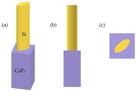
Figure 1.
Schematic diagram of the structure of a meta-atom. (a) Perspective view. (b) Front view. (c) Top view.
The electromagnetic responses of meta-atoms in the range of 4.0–5.0 μm are simulated by using the finite difference time domain (FDTD) method [36]. The FDTD method is proposed by Yee to solve Maxwell’s equations numerically. The basic idea is to make differential approximation of Maxwell’s curl equation:
where μ is the magnetic permeability, ε is the dielectric constant, ρ is the magnetoresistance, and σ is the conductivity. Then, the time domain response of materials under the electromagnetic pulses can be calculated [37,38,39]. In the simulation, the period of meta-atoms is set to be 1.9 μm, and the height of nanoposts and substrate are set to be 5 μm and 4 μm, respectively. The lengths of the major and minor axes of the ellipse are limited within the range of 0.2–1.8 μm. The electromagnetic wave is normally incident to the meta-atom from the substrate side along the Z-axis direction. The periodic boundary condition is used along the X-axis and Y-axis directions, and the perfectly matched layer (PML) is used along the Z-axis direction. After obtaining the responses of meta-atoms in the working waveband, we should filter them. First, structures with low transmittance should be avoided, which will reduce the working efficiency. Second, it can be known from Equation (5) that is a linear function of frequency. Therefore, the phase modulation ability of meta-atoms should be as close to linear as possible with frequency changing. After filtering, the range of the phase dispersion value of the meta-atoms reaches 270°.
4. Result and Discussion
4.1. Regular Negative Dispersion
First, we design a FVBG with regular negative dispersion as a comparison. Here, we only use the PB phase to satisfy Equation (1). The working waveband is 4.0–5.0 μm, and the reference wavelength is set to be 4.3 μm. The focal length at the reference wavelength is 70 μm with the topological charge of 1 and the diameter of 72.2 μm. The characteristic is also simulated using FDTD method, and PML is used in all the three axes. Figure 2 and Figure A1 show the simulated electric field intensity on the x-z plane. The intensities are normalized to their respective maximum. The value of focal length is shown in Figure A2.
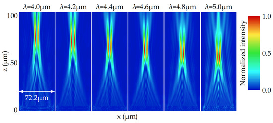
Figure 2.
The simulated electric field intensity on the x-z plane for the FVBG with regular negative dispersion between 4.0 and 5.0 μm.
It can be seen that the FVBG exhibits converging properties in the whole working waveband. At 4.3 μm, the focal length is 70.4 μm, close to the design value. In addition, in the entire waveband, the focal length decreases with increasing wavelength, and the change in focal length reaches 21.0 μm.
The electric field distribution on the respective focal plane between 4.0 and 5.0 μm is shown in Figure 3. Figure 3a is the normalized electric field intensity, and Figure 3b is the phase distribution. It can be seen that the intensity distribution at the focal plane is a ring, different from the focusing characteristics of metalenses. The wavefront is spirally distributed, and the phase change around the center is 360°, consistent with the topological charge of 1. In addition, the background noise gradually increases as it moves away from the reference wavelength. This phenomenon is due to the fact that the used meta-atom has the highest cross-polarization conversion ratio at 4.3 μm. As the working wavelength gradually moves away from 4.3 μm, the phase modulation difference to a set of orthogonal linear polarization states gradually deviates from 180°, which causes a decrease in the cross-polarization conversion ratio, resulting in a decrease in working performance.
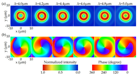
Figure 3.
The simulated electric field distribution for the FVBG with regular negative dispersion on the focal plane between 4.0 and 5.0 μm. (a) Normalized intensity. (b) Phase.
4.2. Zero Dispersion
Next, we design a FVBG with zero dispersion. The working waveband, diameter, topological charge, reference wavelength, and the focal length at the reference wavelength remain unchanged. Unlike the FVBG with regular negative dispersion, meta-atoms with different phase dispersion values are used. The meta-atoms with large phase dispersion values are placed in the center, while the meta-atoms with small phase dispersion values are placed at the edge. Figure 4 and Figure A1 show the simulated electric field intensity on the x-z plane, and the value of focal length is also shown in Figure A2.
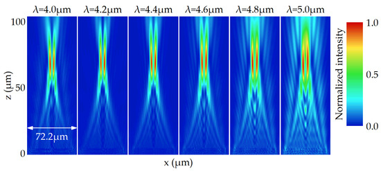
Figure 4.
The simulated electric field intensity on the x-z plane for the FVBG with zero dispersion between 4.0 and 5.0 μm.
It can be clearly seen that the focal position remains almost unchanged in the entire working waveband. At 4.3 μm, the focal length is 69.4 μm, close to the design value. Between 4.0 and 5.0 μm, the variation of focal length is only 2.3 μm, just 11 percent of that of FVBG with regular negative dispersion. The chromatic error is well suppressed. The electric field distributions at the focal plane between 4.0 and 5.0 μm are shown in Figure 5. The characteristic of the background noise is similar to that in Figure 3, and the reasons are the same. In addition, it can be seen that the radius of the focusing ring becomes significantly larger with the increasing working wavelength. This phenomenon is due to the fact that the radius of the focusing ring is related to the focal length and the working wavelength. Among the entire waveband, the focal length remains unchanged. As the wavelength increases, the diffraction effect will also increase, making the radius of focusing ring gradually larger, similar to the Airy disk.
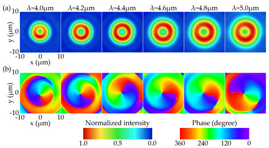
Figure 5.
The simulated electric field distribution for the FVBG with zero dispersion on the focal plane between 4.0 and 5.0 μm. (a) Normalized intensity. (b) Phase.
In order to further verify the generality of the method, we design a zero-dispersion FVBG with a topological charge of 2, and other parameters remain the same. The simulation results show that in the range of 4.0–5.0 μm, the change in focal length is 2.9 μm, i.e., slightly larger than that when l = 1. This difference can be considered as the simulation error. The simulated electric field distribution on the focal plane is shown in Figure A3. It can be seen that the radius of the focusing ring becomes larger, compared with Figure 5. However, it still maintains the trend that the focusing ring becomes larger as the wavelength increases. In the phase distribution diagram, the phase change around the center is 720°, consistent with the topological charge of 2.
4.3. Positive Dispersion
In this section, we design a FVBG with positive dispersion, and the parameters remain the same as that of FVBG with regular negative dispersion. Compared with the FVBG with zero dispersion, the meta-atom with a large phase dispersion value is still located in the center, and the meta-atom with a small phase dispersion value is located at the edge. However, the phase dispersion value of meta-atoms here has a larger gradient along the radial direction. Figure 6 and Figure A1 show the simulated electric field intensity on the x-z plane, and the value of focal length is also shown in Figure A2.
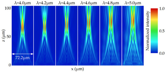
Figure 6.
The simulated electric field intensity on the x-z plane for the FVBG with positive dispersion between 4.0 and 5.0 μm.
As expected, the focal length increases with the increasing wavelength, similar to the conventional refractive lenses. Among the entire working waveband, the variation of the focal length reaches 14.2 μm. With the diameter, the focal length at the reference wavelength, and the working waveband fixed, the focal length variation is limited by the range of the phase dispersion value. Figure 7 shows the electric field distributions at the focal plane between 4.0 and 5.0 μm. It can be seen that the radius of the focusing ring varies with wavelength in a similar fashion to that of Figure 5a, but with a larger magnitude.
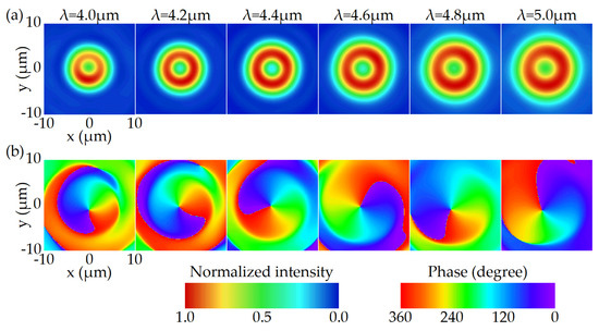
Figure 7.
The simulated electric field distribution for the FVBG with positive dispersion on the focal plane between 4.0 and 5.0 μm. (a) Normalized intensity. (b) Phase.
4.4. Hyper-Negative Dispersion
As for the FVBG with hyper-negative dispersion, the meta-atom with a small phase dispersion value is located in the center, and the meta-atom with a large phase dispersion value is located at the edge, demonstrating the opposite arrangement to the FVBG with zero dispersion. Figure 8 and Figure A1 show the simulated electric field intensity on the x-z plane, and the value of focal length is also shown in Figure A2.
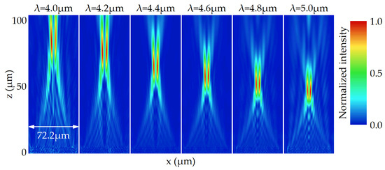
Figure 8.
The simulated electric field intensity on the x-z plane for the FVBG with hyper-negative dispersion between 4.0 and 5.0 μm.
We can see that the focal length decreases rapidly with the increasing wavelength, and the focal length variation reaches 38.3 μm, about 183 percent of that of FVBG with regular negative dispersion. Similar to the FVBG with positive dispersion, the focal length variation is also limited by the range of the phase dispersion value here. Figure 9 shows the electric field distributions at the focal plane between 4.0 and 5.0 μm. In contrast to Figure 5 and Figure 7, the radius of the focusing ring decreases with the increasing wavelength. This difference stems from the fact that the effects of shorter focal lengths outweigh the effects of the increasing wavelength.
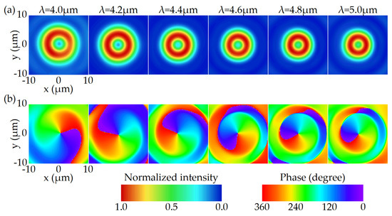
Figure 9.
The simulated electric field distribution for the FVBG with hyper-negative dispersion on the focal plane between 4.0 and 5.0 μm. (a) Normalized intensity. (b) Phase.
5. Conclusions
In conclusion, we show that the dispersion characteristic of a FVBG can be controlled using metasurfaces. When only the geometric phase is used, the FVBG exhibits regular negative dispersion characteristics, and its focal length decreases with the increase in the working wavelength. By using different arrangements of meta-atoms with different electromagnetic responses, the characteristics of zero dispersion, positive dispersion, and hyper-negative dispersion are achieved, respectively. In particular, the radius of the ring on the focal plane of a FVBG with zero dispersion or positive dispersion increases as the wavelength increases, while the radius of the ring on the focal plane of a FVBG with hyper-negative dispersion decreases as the wavelength increases. We believe that our work can play an important role in the practical application of metasurface-based structured beam generation.
Author Contributions
Conceptualization, Z.F.; Methodology, X.L.; Writing—original draft, X.L.; Writing—review and editing, Z.F. All authors have read and agreed to the published version of the manuscript.
Funding
This research received no external funding.
Conflicts of Interest
The authors declare no conflict of interest.
Appendix A
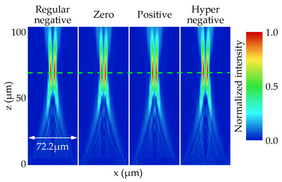
Figure A1.
The simulated electric field intensity on the x-z plane for the four FVBGs at 4.3 μm. The green line indicates 70 μm.
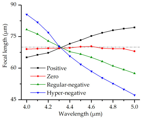
Figure A2.
The focal length of the four FVBGs as a function of wavelength. The dotted line indicates 70 μm.
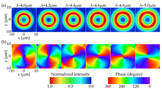
Figure A3.
The simulated electric field distribution for the FVBG with zero dispersion on the focal plane between 4.0 and 5.0 μm at l = 2. (a) Normalized intensity. (b) Phase.
References
- Zhao, D.; Jin, Y.; Wang, B.Z.; Zang, R. Time reversal based broadband synthesis method for arbitrarily structured beam-steering arrays. IEEE Trans. Antennas Propag. 2011, 60, 164–173. [Google Scholar] [CrossRef]
- Sharma, S.; Dey, T.N. Phase-induced transparency-mediated structured-beam generation in a closed-loop tripod configuration. Phys. Rev. A 2017, 96, 033811. [Google Scholar] [CrossRef] [Green Version]
- Auyeung, R.C.; Kim, H.; Mathews, S.; Piqué, A. Laser forward transfer using structured light. Opt. Express 2015, 23, 422–430. [Google Scholar] [CrossRef] [PubMed]
- Sharma, V.; Kumar, S.C.; Samanta, G.K.; Ebrahim-Zadeh, M. Multi-structured-beam optical parametric oscillator. Opt. Express 2020, 28, 21650–21658. [Google Scholar] [CrossRef] [PubMed]
- Allen, L.; Beijersbergen, M.W.; Spreeuw, R.J.C.; Woerdman, J.P. Orbital angular momentum of light and the transformation of Laguerre-Gaussian laser modes. Phys. Rev. A 1992, 45, 8185. [Google Scholar] [CrossRef] [PubMed]
- Ng, J.; Lin, Z.; Chan, C.T. Theory of optical trapping by an optical vortex beam. Phys. Rev. Lett. 2010, 104, 103601. [Google Scholar] [CrossRef] [PubMed] [Green Version]
- Liu, K.; Cheng, Y.; Gao, Y.; Li, X.; Qin, Y.; Wang, H. Super-resolution radar imaging based on experimental OAM beams. Appl. Phys. Lett. 2017, 110, 164102. [Google Scholar] [CrossRef]
- Shao, W.; Huang, S.; Liu, X.; Chen, M. Free-space optical communication with perfect optical vortex beams multiplexing. Opt. Commun. 2018, 427, 545–550. [Google Scholar] [CrossRef]
- Milione, G.; Nguyen, T.A.; Nolan, D.A.; Karimi, E.; Slussarenko, S.; Marrucci, L.; Alfano, R.R. Superdense coding with vector vortex beams: A classical analogy of entanglement. In Proceedings of the Frontiers in Optics 2013, Orlando, FL, USA, 6–10 October 2013. [Google Scholar] [CrossRef]
- Khonina, S.N.; Ustinov, A.V.; Logachev, V.I.; Porfirev, A.P. Properties of vortex light fields generated by generalized spiral phase plates. Phys. Rev. A 2020, 101, 043829. [Google Scholar] [CrossRef]
- Chen, R.; Wang, J.; Zhang, X.; Yao, J.; Ming, H.; Wang, A. Fiber-based mode converter for generating optical vortex beams. Opto-Electron. Adv. 2018, 1, 180003. [Google Scholar] [CrossRef] [Green Version]
- Khonina, S.N.; Karpeev, S.V.; Butt, M.A. Spatial-light-modulator-based multichannel data transmission by vortex beams of various orders. Sensors 2021, 21, 2988. [Google Scholar] [CrossRef] [PubMed]
- Aieta, F.; Genevet, P.; Kats, M.A.; Yu, N.; Blanchard, R.; Gaburro, Z.; Capasso, F. Aberration-free ultrathin flat lenses and axicons at telecom wavelengths based on plasmonic metasurfaces. Nano Lett. 2012, 12, 4932–4936. [Google Scholar] [CrossRef] [PubMed]
- Khorasaninejad, M.; Zhu, A.Y.; Roques-Carmes, C.; Chen, W.T.; Oh, J.; Mishra, I.; Devlin, R.C.; Capasso, F. Polarization-insensitive metalenses at visible wavelengths. Nano Lett. 2016, 16, 7229–7234. [Google Scholar] [CrossRef] [PubMed]
- Yu, N.; Genevet, P.; Kats, M.A.; Aieta, F.; Tetienne, J.P.; Capasso, F.; Gaburro, Z. Light propagation with phase discontinuities: Generalized laws of reflection and refraction. Science 2011, 334, 333–337. [Google Scholar] [CrossRef] [PubMed] [Green Version]
- Abdelsalam, M.; Mahmoud, A.M.; Swillam, M.A. Polarization independent dielectric metasurface for infrared beam steering applications. Sci. Rep. 2019, 9, 1–7. [Google Scholar] [CrossRef]
- Ni, X.; Kildishev, A.V.; Shalaev, V.M. Metasurface holograms for visible light. Nat. Commun. 2013, 4, 1–6. [Google Scholar] [CrossRef]
- Wen, D.; Yue, F.; Li, G.; Zheng, G.; Chan, K.; Chen, S.; Chen, M.; Li, K.F.; Wong, P.W.H.; Cheah, K.W.; et al. Helicity multiplexed broadband metasurface holograms. Nat. Commun. 2015, 6, 1–7. [Google Scholar] [CrossRef] [PubMed]
- Ma, X.; Pu, M.; Li, X.; Huang, C.; Wang, Y.; Pan, W.; Zhao, B.; Cui, J.; Wang, C.; Zhao, Z.; et al. A planar chiral meta-surface for optical vortex generation and focusing. Sci. Rep. 2015, 5, 1–7. [Google Scholar] [CrossRef] [PubMed] [Green Version]
- Mehmood, M.Q.; Mei, S.; Hussain, S.; Huang, K.; Siew, S.Y.; Zhang, L.; Zhang, T.; Ling, X.; Liu, H.; Teng, J.; et al. Visible-frequency metasurface for structuring and spatially multiplexing optical vortices. Adv. Mater. 2016, 28, 2533–2539. [Google Scholar] [CrossRef] [PubMed]
- Shi, Z.; Khorasaninejad, M.; Huang, Y.W.; Roques-Carmes, C.; Zhu, A.Y.; Chen, W.T.; Sanjeev, V.; Ding, Z.W.; Tamagone, M.; Chaudhary, K.; et al. Single-layer metasurface with controllable multiwavelength functions. Nano Lett. 2018, 18, 2420–2427. [Google Scholar] [CrossRef] [PubMed]
- Liu, X.; Deng, J.; Jin, M.; Tang, Y.; Zhang, X.; Li, K.F.; Li, G. Cassegrain metasurface for generation of orbital angular momentum of light. Appl. Phys. Lett. 2019, 115, 221102. [Google Scholar] [CrossRef]
- Ding, F.; Chen, Y.; Bozhevolnyi, S.I. Focused vortex-beam generation using gap-surface plasmon metasurfaces. Nanophotonics 2020, 9, 371–378. [Google Scholar] [CrossRef] [Green Version]
- Tang, S.; Ding, F. High-efficiency focused optical vortex generation with geometric gap-surface plasmon metalenses. Appl. Phys. Lett. 2020, 117, 011103. [Google Scholar] [CrossRef]
- Yuan, Y.; Ding, X.; Zhang, K.; Wu, Q. Planar efficient metasurface for vortex beam generating and converging in microwave region. IEEE Trans. Magn. 2017, 53, 1–4. [Google Scholar] [CrossRef]
- Ou, K.; Li, G.; Li, T.; Yang, H.; Yu, F.; Chen, J.; Zhao, Z.; Cao, G.; Chen, X.; Lu, W. High efficiency focusing vortex generation and detection with polarization-insensitive dielectric metasurfaces. Nanoscale 2018, 10, 19154–19161. [Google Scholar] [CrossRef] [PubMed]
- Wang, S.; Wu, P.C.; Su, V.C.; Lai, Y.C.; Chu, C.H.; Chen, J.W.; Lu, S.H.; Chen, J.; Xu, B.; Kuan, C.H.; et al. Broadband achromatic optical metasurface devices. Nat. Commun. 2017, 8, 1–9. [Google Scholar] [CrossRef] [PubMed]
- Chen, W.T.; Zhu, A.Y.; Sanjeev, V.; Khorasaninejad, M.; Shi, Z.; Lee, E.; Capasso, F. A broadband achromatic metalens for focusing and imaging in the visible. Nat. Nanotechnol. 2018, 13, 220–226. [Google Scholar] [CrossRef] [PubMed] [Green Version]
- Kang, M.; Feng, T.; Wang, H.T.; Li, J. Wave front engineering from an array of thin aperture antennas. Opt. Express 2012, 20, 15882–15890. [Google Scholar] [CrossRef] [PubMed]
- Khorasaninejad, M.; Chen, W.T.; Devlin, R.C.; Oh, J.; Zhu, A.Y.; Capasso, F. Metalenses at visible wavelengths: Diffraction-limited focusing and subwavelength resolution imaging. Science 2016, 352, 1190–1194. [Google Scholar] [CrossRef] [PubMed] [Green Version]
- Mueller, J.P.B.; Rubin, N.A.; Devlin, R.C.; Groever, B.; Capasso, F. Metasurface polarization optics: Independent phase control of arbitrary orthogonal states of polarization. Phys. Rev. Lett. 2017, 118, 113901. [Google Scholar] [CrossRef] [PubMed] [Green Version]
- Arbabi, A.; Horie, Y.; Ball, A.J.; Bagheri, M.; Faraon, A. Subwavelength-thick lenses with high numerical apertures and large efficiency based on high-contrast transmitarrays. Nat. Commun. 2015, 6, 1–6. [Google Scholar] [CrossRef] [PubMed]
- Khorasaninejad, M.; Shi, Z.; Zhu, A.Y.; Chen, W.T.; Sanjeev, V.; Zaidi, A.; Capasso, F. Achromatic metalens over 60 nm bandwidth in the visible and metalens with reverse chromatic dispersion. Nano Lett. 2017, 17, 1819–1824. [Google Scholar] [CrossRef] [PubMed]
- Arbabi, E.; Arbabi, A.; Kamali, S.M.; Horie, Y.; Faraon, A. Controlling the sign of chromatic dispersion in diffractive optics with dielectric metasurfaces. Optica 2017, 4, 625–632. [Google Scholar] [CrossRef]
- Li, L.; Yuan, Q.; Chen, R.; Zou, X.; Zang, W.; Li, T.; Zheng, G.; Wang, S.; Wang, Z.; Zhu, S. Chromatic dispersion manipulation based on metasurface devices in the mid-infrared region. Chin. Opt. Lett. 2020, 18, 082401. [Google Scholar] [CrossRef]
- Yee, K. Numerical solution of initial boundary value problems involving Maxwell’s equations in isotropic media. IEEE Trans. Antennas Propag. 1966, 14, 302–307. [Google Scholar] [CrossRef] [Green Version]
- Mur, G. Absorbing boundary conditions for the finite-difference approximation of the time-domain electromagnetic-field equations. IEEE Trans. Electromagn. Compat. 1981, 4, 377–382. [Google Scholar] [CrossRef]
- Chaudhury, B.; Boeuf, J.P. Computational studies of filamentary pattern formation in a high power microwave breakdown generated air plasma. IEEE Trans. Plasma Sci. 2010, 38, 2281–2288. [Google Scholar] [CrossRef]
- Moxley III, F.I.; Chuss, D.T.; Dai, W. A generalized finite-difference time-domain scheme for solving nonlinear Schrödinger equations. Comput. Phys. Commun. 2013, 184, 1834–1841. [Google Scholar] [CrossRef]
Publisher’s Note: MDPI stays neutral with regard to jurisdictional claims in published maps and institutional affiliations. |
© 2022 by the authors. Licensee MDPI, Basel, Switzerland. This article is an open access article distributed under the terms and conditions of the Creative Commons Attribution (CC BY) license (https://creativecommons.org/licenses/by/4.0/).