Communication

Dispersion Analysis of Twist-Symmetric Dielectric Waveguides

1
Division of Electromagnetic Engineering, KTH Royal Institute of Technology, 114 28 Stockholm, Sweden
2
Department of Applied Physics 1, E.T.S. de Ingeniería Informática, University of Seville, 41012 Seville, Spain
3
Faculty of Electrical Engineering and Computing, University of Zagreb, Unska 3, 10000 Zagreb, Croatia
*
Author to whom correspondence should be addressed.
Photonics 2021, 8(6), 206; https://doi.org/10.3390/photonics8060206
Submission received: 27 April 2021 / Revised: 1 June 2021 / Accepted: 3 June 2021 / Published: 8 June 2021
(This article belongs to the Special Issue Advances in Complex Media Electromagnetics)

Abstract

:
We propose a circular twist-symmetric dielectric waveguide that is polarization-selective. In the practical implementation of optical fibers, a selective circular polarization is more convenient than its linearly polarized counterpart where previous knowledge of the emitted polarization from the transmitter is unknown. The analysis of the waveguide was conducted with three methods: an eigenmode approach, simulation of a truncated structure, and the so-called multimodal transfer-matrix method (MMTMM). The presented simulations demonstrate that the operational band can be manipulated by tuning the parameters of the structure. Furthermore, the MMTMM allows for a direct and accurate calculation of the attenuation constant of the rejected circular polarization.

1. Introduction

The electromagnetic properties of periodic structures with higher symmetries were first studied in the 1960s and 1970s [1,2,3]. Their properties have recently been revisited after the discovery of novel and interesting characteristics in two-dimensional periodic structures [4,5,6]. Two types of spatial higher symmetries can be found in the literature: glide and twist symmetry. A periodic structure possesses glide symmetry if it is invariant after a translation and a mirroring [7,8]. Glide-symmetric structures have been demonstrated to exhibit lower dispersion and higher refractive indices than conventional structures [4], properties that are found useful when designing two-dimensional lens antennas [9,10,11,12]. Moreover, introducing glide symmetry in conventional electromagnetic band gap structures enables a broader rejection band and higher attenuation [13,14]. This characteristic has been exploited in the design of filters [15,16], components based on gap waveguide technology [17,18], and to avoid leakage in the interconnection of waveguides [19,20]. Other reported properties of glide symmetry include enhanced on-axis anisotropy [12,21] and magnetic permeability [22].
Twist-symmetric structures remain in turn invariant after N consecutive translations and rotations of 2 π / N rad [7]. Like glide symmetry, twist symmetry reduces the dispersion of periodic structures and increases its equivalent refractive index [23]. These properties were experimentally demonstrated in coaxial lines [24,25] and hollow waveguides [26]. Making use of a mode-matching technique, it was demonstrated in [27] that this reduction in dispersion is caused by the higher-order modal coupling between the sub-perturbations within the unit cell. The properties of twist symmetries have been used to produce reconfigurable stopbands [25] and phase shifts [26]. Metallic cylinders possessing twist symmetry were employed to produce filters in [28]. Moreover, the increase in the equivalent refractive index in twist-symmetric structures was used to reduce the size of helix antennas [29] and to produce compact lenses [30]. Twist symmetry was also proposed for stacked Frequency Selective Surfaces resulting in broadband polarizers for millimeter waves [31,32]. This kind of polarizers can also be found in the optical range [33], which can be useful for detection of enantiomers [34].
Most of the higher-symmetric structures studied in the literature are bounded structures and, specifically, all the twist-symmetric structures mentioned above were bounded, i.e., the structure was placed inside a PEC enclosure—the outside wall of the waveguide structure. So far, one case of an unbounded glide-symmetric dielectric waveguide was studied in [35]. In the present work, we analyze the propagation characteristics of an open fully dielectric structure with twist symmetry as illustrated in Figure 1. Here, a circular waveguide has twist-symmetric elliptic cylinders embedded.
The polarization selection exhibited by the structure with three-fold twist symmetry is of practical interest. This feature of mono-polarized propagation is desired in fibers since the feeding will be independent of the setup [36]. A similar feature was already proposed with the use of chiral fibers in [37] where a double helix was placed around a fiber. This helix could be seen as an infinite-fold twist-symmetric structure [38]. Another example can be found in [39], where a dielectric ribbon waveguide was proposed for sub-THz communications. Therefore, given the recent advances and development of additive manufacturing [40,41], twist-symmetric dielectric structures can be of interest for future wired communication systems allocated in the sub-THz frequency band.
Due to the geometric complexity and dielectric nature of the structure under study, as well as the strong mode coupling within it, its detailed analysis can only be carried by means of purely numerical approaches. It is well known that, in a conventional dielectric rod, the mono-modal operation is determined by the following V number condition: V 2.405 [42], which depends on the diameter and dielectric constant. In principle, this is the only parameter that can be known a priori and that gives us an approximation of the mono-modal operation frequency of our twist-symmetric dielectric waveguide. Hence, the three methods of analysis to be used in this work are: (1) the eigenmode solver of a commercial full-wave simulator (CST Microwave Studio in this work), (2) time-domain simulation of a truncated structure, and (3) the multimodal transfer-matrix method. In the next sections, some results and relevant features of these three approaches are reported.

2. Results and Discussion

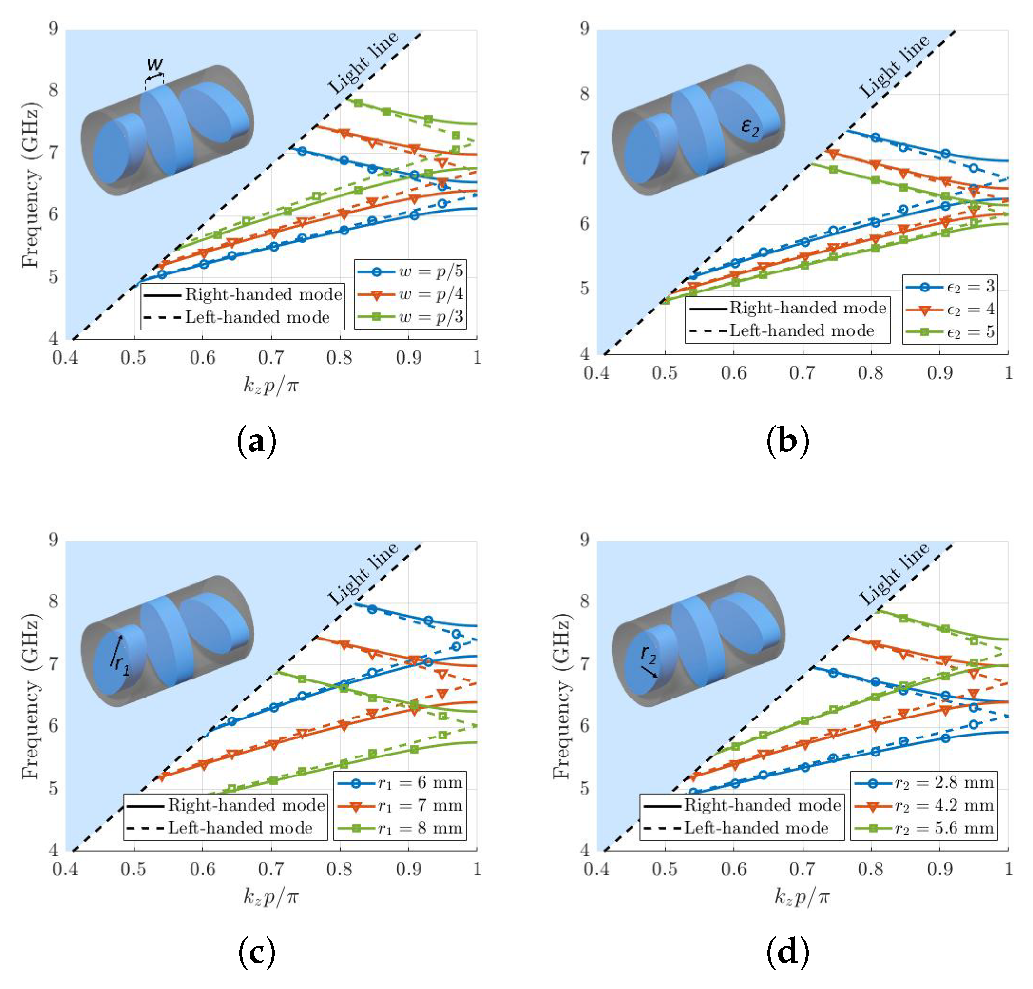
2.1. Eigenmode Solver

To conduct the simulations with the eigenmode solver in CST, a perfect electric conductor was introduced at an electrically large distance from the unit cell. In Figure 2a, the dispersion diagram of a two-fold structure is shown. This structure produces two linear polarized modes which are not identical. In Figure 2b, the dispersion diagram of two circularly polarized HE 11 modes are illustrated for the case of three-fold twist symmetry. The results provided by the eigenmode solver in CST reveal that, while the left-handed circularly-polarized (LCP) mode does not have a stop band in the first Brillouin zone, the right-handed (RCP) mode has a stopband between 6.4 and 7 GHz. This behaviour is not intrinsic to twist-symmetric structures, since it is found to depend on the order of symmetry. Another example is shown in Figure 2c, where we illustrate the dispersion diagram of two HE 11 modes for a four-fold twist-symmetric structure. In this case, the two modes are linearly polarized and identical since the periodicity of the protrusions are symmetric. Although the results are not presented here for the sake of brevity, a five-fold structure would again excite two circularly polarized HE 11 modes but without a polarization selection property.
In the three-fold case, there is a stopband in the clockwise direction since the protrusions rotate only π rad in one period. However, in the counterclockwise direction, they rotate 2 π rad, so there is no stopband. The rotation of the first three protrusions is illustrated in Figure 3, for both the clockwise and counterclockwise direction. Only in the counterclockwise case does the protrusion return to its original location in exactly one period.
In the rest of this manuscript we will focus on the case of order of symmetry N = 3 due to its polarization selection. The handedness of the propagating modes is illustrated in Figure 4 where the field distribution for different z-planes is plotted.
The first study carried out with the Eigenmode solver is a parametric study of some relevant geometrical features of the waveguide. The effects of different design parameters on the dispersion diagram are shown in Figure 5. The mode that propagates discordantly to the rotation of the protrusions (RCP in our case) has a stopband in the first Brillouin zone. Figure 5a shows that, when increasing the value of w, the stopband moves up in frequency and broadens its bandwidth. In Figure 5b, the effect of the inner material is studied. For lower values of the permittivity, the stopband moves up in frequency, and its bandwidth increases. Figure 5c shows the variations of the stopband for different values of r 1 . It can be appreciated that there is an optimal value for this parameter in terms of bandwidth. Finally, an increase in the value of r 2 also moves it up in frequency, however here its bandwidth is reduced (Figure 5d).

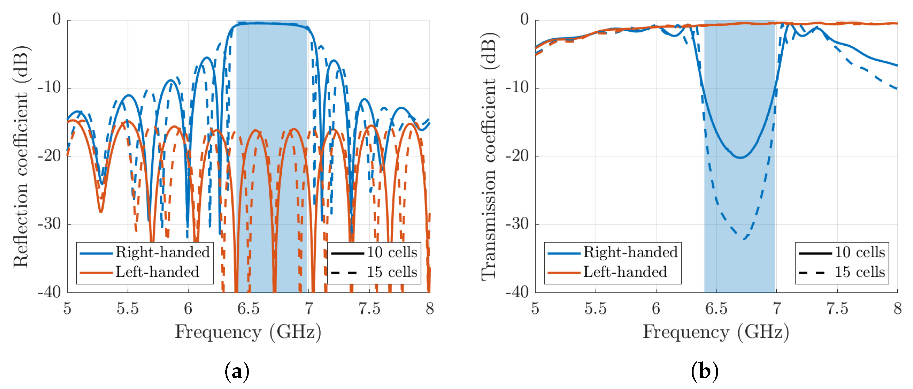
2.2. Frequency Domain Simulation of a Truncated Structure

The periodic dielectric waveguide is studied in this section by means of the Frequency Domain solver in CST through the simulation of finite structures that comprise 10 and 15 unit cells. In these simulations, perfect matching layers are used as boundary conditions. Since the software only provides directly the S-parameters of linearly-polarized modes ( [ S ] LP ), a transformation to circularly-polarized S-parameters ( [ S ] CP ) is needed. This transformation is given by the following operation [43]:
[ S ] CP = 1 2 1 j 0 0 1 j 0 0 0 0 1 j 0 0 1 j [ S ] LP 1 1 0 0 j j 0 0 0 0 1 1 0 0 j j
with the elements of matrices [ S ] CP and [ S ] LP arranged as
[ S ] CP = S 11 RR S 11 RL S 12 RR S 12 RL S 11 LR S 11 LL S 12 LR S 12 LL S 21 RR S 21 RL S 22 RR S 22 RL S 21 LR S 21 LL S 22 LR S 22 LL , [ S ] LP = S 11 XX S 11 XY S 12 XX S 12 XY S 11 YX S 11 YY S 12 YX S 12 YY S 21 XX S 21 XY S 22 XX S 22 XY S 21 YX S 21 YY S 22 YX S 22 YY
where the superscripts L,R and X,Y represent the left/right-handed and x / y -components, respectively.
In Figure 6, both the reflection and transmission coefficients are plotted. A good agreement between 10 and 15 unit cells is achieved confirming a good approximation of the truncation to the infinite periodicity. A high level of reflection is produced by the right-handed mode within the stopband, in which the left-handed mode is largely transmitted. This indicates that the attenuation is associated with the stopband rejection rather than leakage along the open waveguide. The low transmission in lower frequencies is due to the poor confinement of the modes in the waveguide.

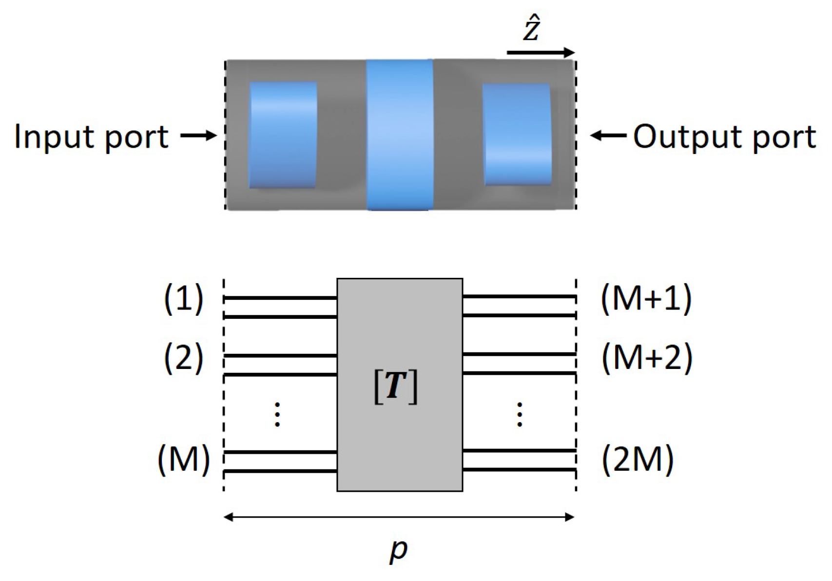
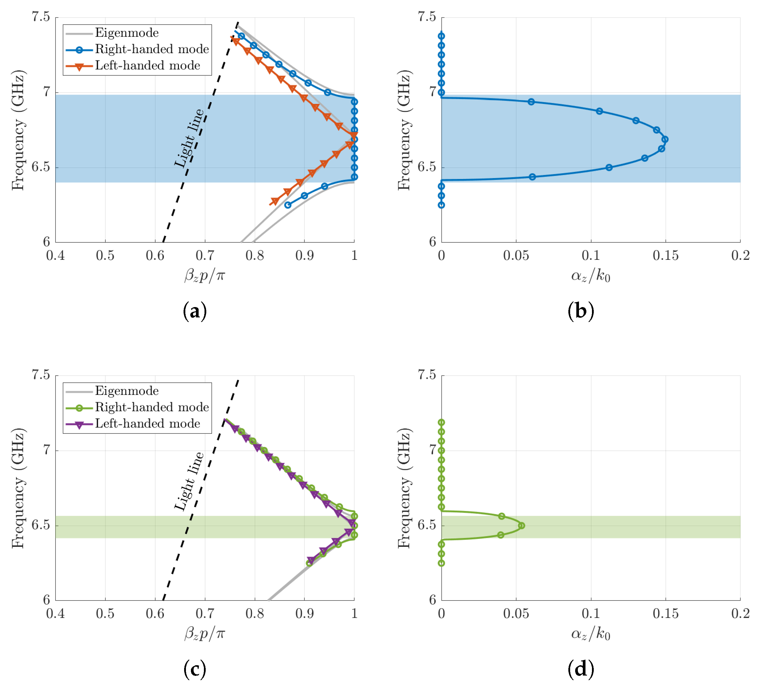
2.3. Multimode Transfer-Matrix Method (MMTMM)

The MMTMM is an efficient hybrid approach able to compute both the phase and attenuation constants of general periodic structures [44]. It links any unit cell with its equivalent transfer matrix [ T ] , which can be calculated by any appropriate commercial/in-house software. Multiple propagative and evanescent modes can be excited in the structure from its ports, as shown in Figure 7. The multimode method was previously validated in [45] for fully-metallic and bounded twist-symmetric structures, including a study on its convergence. Here, we use this method in a more challenging situation in which the configuration is unbounded and it is fully dielectric. Under these conditions, there are hybrid modes which are more difficult to evaluate with commercial software.
Our unit cell has periodicity (p) only in one direction (z), thus the computation of the associated wavenumbers ( k z ) of its different Bloch modes can be obtained after solving the following eigenvalue problem [46,47,48]:
[ T ] V 1 I 1 = e j k z p V 1 I 1
where V i , I i ( i = 1 , 2 ) are the equivalent voltages and currents associated with multiple port modes projected by the Bloch modes inside the unit cell. In the application of this method to the structure in Figure 1b, the transfer matrix is computed by means of the CST Frequency Domain Solver taking the first three excited modes in the ports of the unit cell. Although the three modes are linearly polarized, it is important to remark that a linear-to-circular post-processing of the resulting [ T ] matrix is not necessary. Since the outcome of (2) is the eigenvalues and eigenvectors of the structure, the method successfully finds the wavenumbers of both the LCP and RCP modes. In Figure 8a,c, the phase shifts resulting from the MMTMM and the CST Eigenmode solver are plotted for two different examples. A good agreement between both methods is found in the band of interest. The small disagreement in the width of the stopband can be attributed to the sensitivity of the CST Frequency Domain Solver to the size of the ports. At lower frequencies, the modes computed by CST in this band are not well confined, which also causes some disagreements between the Eigenmode Solver and the MMTMM. Different to the Eigenmode solver, the MMTMM does allow for the calculation of the attenuation constant in the stopband, as plotted in Figure 8b,d. This result is important because it informs of the actual rejection level of this stopband. Thus, Figure 8c,d show that the stopband in the second example is three times narrower than in the first example and its attenuation level is also about three times lower. The maximum value of α z in the first example corresponds to an attenuation of 2.8 dB per unit cell, whereas the results of the truncated structure simulation suggested a value of 2.6 dB per unit cell. The attenuation constant in the truncated structure is calculated by subtracting the transmission scattering parameters of two cases with 15 and 10 unit cells. With this method, we eliminate the effect of the reflections in the transitions.
Finally, a study of the losses was done when lossy materials were used. A value of tan δ = 0.004 is considered, which is a typical value for additive manufacturing ABS materials [49]. In Figure 9, the attenuation constant of the left-handed circular mode is plotted. Both the simulation of a truncated structure and the multimode method are included for comparison. The results of the simulation for the truncated structure were smoothed to remove numerical noise. In the multimode analysis, we found numerical problems to compute the material losses in a narrow band between 6.6 and 6.8 GHz, due to the presence of an spurious stopband attributed to not sufficiently accurate scattering parameters provided by the CST Frequency Domain solver. This stopband has been removed in the figure. Both methods agree well with a discrepancy of around 0.01 dB/m.

3. Conclusions

We proposed a dielectric waveguide embedded with twist-symmetric elliptic cylinders, which is polarization selective. A dispersion analysis was conducted using several different methods (Eigenmode, Time Domain Solver of a truncated structure and multimode transfer matrix method). This analysis revealed that the proposed structure permits the propagation of two circularly-polarized modes whose operational bands can be controlled by their structural parameters. Furthermore, we showed that the Bloch multimode transfer matrix method can be used to calculate the attenuation constant within the stopband of the rejected mode.

Author Contributions

Conceptualization, O.Q.-T.; formal analysis, P.C.-T., K.V.G. and Q.C.; writing—original draft preparation, P.C.-T.; writing—review and editing, K.V.G., Q.C., F.M., Z.S. and O.Q.-T.; visualization, P.C.-T.; supervision, F.M., Z.S. and O.Q.-T. All authors have read and agreed to the published version of the manuscript.

Funding

This article is based upon work from COST Action SyMat CA18223, supported by COST (European Cooperation in Science and Technology), www.cost.eu (accessed on 4 June 2021). The contribution of F. Mesa was also supported by the Spanish Research and Development National Program under Project TEC2017-84724-P.

Institutional Review Board Statement

Not applicable.

Informed Consent Statement

Not applicable.

Data Availability Statement

The data that support the findings of this study are available from the corresponding author upon reasonable request.

Acknowledgments

The authors would like to thank Guido Valerio for helpful discussions.

Conflicts of Interest

The authors declare no conflict of interest.

References

  1. Crepeau, P.J.; McIsaac, P.R. Consequences of symmetry in periodic structures. Proc. IEEE 1964, 52, 33–43. [Google Scholar] [CrossRef] [Green Version]
  2. Mittra, R.; Laxpati, S. Propagation in a wave guide with Glide refection symmetry. Can. J. Phys. 1965, 43, 353–372. [Google Scholar] [CrossRef]
  3. Kieburtz, R.; Impagliazzo, J. Multimode propagation on radiating traveling-wave structures with glide-symmetric excitation. IEEE Trans. Antennas Propag. 1970, 18, 3–7. [Google Scholar] [CrossRef]
  4. Quevedo-Teruel, O.; Ebrahimpouri, M.; Kehn, M.N.M. Ultrawideband metasurface lenses based on off-shifted opposite layers. IEEE Antennas Wireless Propag. Lett. 2016, 15, 484–487. [Google Scholar] [CrossRef]
  5. Quevedo-Teruel, O.; Valerio, G.; Sipus, Z.; Rajo-Iglesias, E. Periodic structures with higher symmetries: Their applications in electromagnetic devices. IEEE Microw. Mag. 2020, 21, 36–49. [Google Scholar] [CrossRef]
  6. Quevedo-Teruel, O.; Chen, Q.; Mesa, F.; Fonseca, N.J.G.; Valerio, G. On the Benefits of Glide Symmetries for Microwave Devices. IEEE J. Microw. 2021, 1, 457–469. [Google Scholar] [CrossRef]
  7. Hessel, A.; Chen, M.H.; Li, R.C.M.; Oliner, A.A. Propagation in periodically loaded waveguides with higher symmetries. Proc. IEEE 1973, 61, 183–195. [Google Scholar] [CrossRef]
  8. Valerio, G.; Ghasemifard, F.; Sipus, Z.; Quevedo-Teruel, O. Glide-symmetric all-metal holey metasurfaces for low-dispersive artificial materials: Modeling and properties. IEEE Trans. Microw. Theory Tech. 2018, 66, 3210–3223. [Google Scholar] [CrossRef] [Green Version]
  9. Quevedo-Teruel, O.; Miao, J.; Mattsson, M.; Algaba-Brazalez, A.; Johansson, M.; Manholm, L. Glide-symmetric fully metallic Luneburg lens for 5G communications at Ka-band. IEEE Antennas Wireless Propag. Lett. 2018, 17, 1588–1592. [Google Scholar] [CrossRef]
  10. Bantavis, P.; Gonzalez, C.G.; Sauleau, R.; Goussetis, G.; Tubau, S.; Legay, H. Broadband graded index Gutman lens with a wide field of view utilizing artificial dielectrics: A design methodology. Opt. Express 2020, 28, 14648–14661. [Google Scholar] [CrossRef]
  11. Fan, F.; Cai, M.; Zhang, J.; Yan, Z.; Wu, J. Wideband low-profile Luneburg lens based on a glide-symmetric metasurface. IEEE Access 2020, 8, 85698–85705. [Google Scholar] [CrossRef]
  12. Chen, Q.; Giusti, F.; Valerio, G.; Mesa, F.; Quevedo-Teruel, O. Anisotropic glide-symmetric substrate-integrated-holey metasurface for a compressed ultrawideband Luneburg lens. Appl. Phys. Lett. 2021, 118, 084102. [Google Scholar] [CrossRef]
  13. Ebrahimpouri, M.; Quevedo-Teruel, O.; Rajo-Iglesias, E. Design guidelines for gap waveguide technology based on glide-symmetric holey structures. IEEE Microw. Wireless Compon. Lett. 2017, 27, 542–544. [Google Scholar] [CrossRef]
  14. Chen, Q.; Mesa, F.; Yin, X.; Quevedo-Teruel, O. Accurate Characterization and Design Guidelines of Glide-Symmetric Holey EBG. IEEE Trans. Microw. Theory Tech. 2020, 68, 4984–4994. [Google Scholar] [CrossRef]
  15. Monje-Real, A.; Fonseca, N.J.G.; Zetterstrom, O.; Pucci, E.; Quevedo-Teruel, O. Holey glide-symmetric filters for 5G at millimeter-wave frequencies. IEEE Microw. Wireless Compon. Lett. 2020, 30, 31–34. [Google Scholar] [CrossRef]
  16. Palomares-Caballero, A.; Alex-Amor, A.; Padilla, P.; Valenzuela-Valdes, J.F. Dispersion and filtering properties of rectangular waveguides loaded with holey structures. IEEE Trans. Microw. Theory Tech. 2020, 68, 5132–5144. [Google Scholar] [CrossRef]
  17. Ebrahimpouri, M.; Rajo-Iglesias, E.; Sipus, Z.; Quevedo-Teruel, O. Cost-effective gap waveguide technology based on glide-symmetric holey EBG structures. IEEE Trans. Microw. Theory Tech. 2018, 66, 927–934. [Google Scholar] [CrossRef] [Green Version]
  18. Vosoogh, A.; Zirath, H.; He, Z.S. Novel air-filled waveguide transmission line based on multilayer thin metal plates. IEEE Trans. Terahertz Sci. Technol. 2019, 9, 282–290. [Google Scholar] [CrossRef]
  19. Ebrahimpouri, M.; Algaba Brazalez, A.; Manholm, L.; Quevedo-Teruel, O. Using glide-symmetric holes to reduce leakage between waveguide flanges. IEEE Microw. Wireless Compon. Lett. 2018, 28, 473–475. [Google Scholar] [CrossRef]
  20. He, Z.S.; An, S.; Liu, J.; Jin, C. Variable high precision wide D-band phase shifter. IEEE Access 2020, 8, 140438–140444. [Google Scholar] [CrossRef]
  21. Ebrahimpouri, M.; Quevedo-Teruel, O. Ultrawideband anisotropic glide-symmetric metasurfaces. IEEE Antennas Wireless Propag. Lett. 2019, 18, 1547–1551. [Google Scholar] [CrossRef]
  22. Ebrahimpouri, M.; Herran, L.F.; Quevedo-Teruel, O. Wide-angle impedance matching using glide-symmetric metasurfaces. IEEE Microw. Wireless Compon. Lett. 2020, 30, 8–11. [Google Scholar] [CrossRef]
  23. Dahlberg, O.; Ghasemifard, F.; Valerio, G.; Quevedo-Teruel, O. Propagation characteristics of periodic structures possessing twist and polar glide symmetries. EPJ Appl. Metamat. 2019, 6. [Google Scholar] [CrossRef] [Green Version]
  24. Dahlberg, O.; Mitchel-Thomas, R.C.; Quevedo-Teruel, O. Reducing the dispersion of periodic structures with twist and polar glide symmetries. Sci. Rep. 2017, 7, 1–6. [Google Scholar] [CrossRef]
  25. Ghasemifard, F.; Norgren, M.; Quevedo-Teruel, O. Twist and polar glide symmetries: An additional degree of freedom to control the propagation characteristics of periodic structures. Sci. Rep. 2018, 8, 11266. [Google Scholar] [CrossRef] [PubMed] [Green Version]
  26. Quevedo-Teruel, O.; Dahlberg, O.; Valerio, G. Propagation in waveguides with transversal twist-symmetric holey metallic plates. IEEE Microw. Wireless Compon. Lett. 2018, 28, 858–860. [Google Scholar] [CrossRef]
  27. Dahlberg, O.; Valerio, G.; Mesa, F.; Ghasemifard, F.; Norgren, M.; Quevedo-Teruel, O. Dispersion analysis of periodically loaded transmission lines with twist symmetry using the mode-matching technique. Appl. Sci. 2020, 10, 5990. [Google Scholar] [CrossRef]
  28. Bastioli, S.; Snyder, R.V. Nonresonating modes do it better!: Exploiting additional modes in conjunction with operating modes to design better quality filters. IEEE Microw. Mag. 2021, 22, 20–45. [Google Scholar] [CrossRef]
  29. Palomares-Caballero, A.; Padilla, P.; Alex-Amor, A.; Valenzuela-Valdés, J.; Quevedo-Teruel, O. Twist and glide symmetries for helix antenna design and miniaturization. Symmetry 2019, 11, 349. [Google Scholar] [CrossRef] [Green Version]
  30. Dahlberg, O.; Valerio, G.; Quevedo-Teruel, O. Fully metallic flat lens based on locally twist-symmetric array of complementary split-ring resonators. Symmetry 2019, 11, 581. [Google Scholar] [CrossRef] [Green Version]
  31. Wei, Z.; Cao, Y.; Fan, Y.; Yu, X.; Li, H. Broadband polarization transformation via enhanced asymmetric transmission through arrays of twisted complementary split-ring resonators. Appl. Phys. Lett. 2011, 99, 221907. [Google Scholar] [CrossRef] [Green Version]
  32. Alex-Amor, A.; Mesa, F.; Palomares-Caballero, Á.; Molero, C.; Padilla, P. Exploring the potentials of the multi-modal equivalent circuit approach for stacks of 2-D aperture arrays. IEEE Trans. Antennas Propag. Early access. [CrossRef]
  33. Zhao, Y.; Belkin, M.A.; Alù, A. Twisted optical metamaterials for planarized ultrathin broadband circular polarizers. Nat. Commun. 2012, 3. [Google Scholar] [CrossRef] [PubMed] [Green Version]
  34. Zhao, Y.; Askarpour, A.N.; Sun, L.; Shi, J.; Li, X.; Alù, A. Chirality detection of enantiomers using twisted optical metamaterials. Nat. Commun. 2017, 8. [Google Scholar] [CrossRef] [PubMed]
  35. Sipus, Z.; Bosiljevac, M. Modeling of glide-symmetric dielectric structures. Symmetry 2019, 11, 805. [Google Scholar] [CrossRef] [Green Version]
  36. Chiral Photonics. Available online: https://chiralphotonics.com/ (accessed on 1 June 2021).
  37. Kopp, V.I.; Genack, A.Z. Double-helix chiral fibers. Opt. Lett. 2003, 28, 1876–1878. [Google Scholar] [CrossRef] [PubMed]
  38. Sensiper, S. Electromagnetic Wave Propagation on Helical Structures (A Review and Survey of Recent Progress). Proc. IRE 1955, 43, 149–161. [Google Scholar] [CrossRef]
  39. Malekabadi, A.; Charlebois, S.A.; Deslandes, D.; Boone, F. High-Resistivity Silicon Dielectric Ribbon Waveguide for Single-Mode Low-Loss Propagation at F/G-Bands. IEEE Trans. Terahertz Sci. Technol. 2014, 4, 447–453. [Google Scholar] [CrossRef]
  40. Lugo, D.C.; Ramirez, R.A.; Wang, J.; Weller, T.M. Multilayer Dielectric End-Fire Antenna with Enhanced Gain. IEEE Antennas Wireless Propag. Lett. 2018, 17, 2213–2217. [Google Scholar] [CrossRef]
  41. Lugo, D.C.; Wang, J.; Weller, T.M. Analytical and Experimental Study of Multilayer Dielectric Rod Waveguides. IEEE Trans. Microw. Theory Tech. 2021, 69, 2088–2097. [Google Scholar] [CrossRef]
  42. Keiser, G. Optical Fiber Communications, 4th ed.; McGraw-Hill: New York, NY, USA, 2011. [Google Scholar]
  43. Ericsson, A.; Lundgren, J.; Sjöberg, D. Experimental characterization of circular polarization selective structures using linearly single-polarized antennas. IEEE Trans. Antennas Propag. 2017, 65, 4239–4249. [Google Scholar] [CrossRef]
  44. Mesa, F.; Valerio, G.; Rodriguez-Berral, R.; Quevedo-Teruel, O. Simulation-assisted efficient computation of the dispersion diagram of periodic structures: A comprehensive overview with applications to filters, leaky-wave antennas and metasurfaces. IEEE Antennas Propag. Mag. 2020. [Google Scholar] [CrossRef]
  45. Bagheriasl, M.; Valerio, G. Bloch analysis of electromagnetic waves in twist-symmetric lines. Symmetry 2019, 11, 620. [Google Scholar] [CrossRef] [Green Version]
  46. Valerio, G.; Paulotto, S.; Baccarelli, P.; Burghignoli, P.; Galli, A. Accurate Bloch analysis of 1-D periodic lines through the simulation of truncated structures. IEEE Trans. Antennas Propag. 2011, 59, 2188–2195. [Google Scholar] [CrossRef]
  47. Bagheriasl, M.; Quevedo-Teruel, O.; Valerio, G. Bloch analysis of artificial lines and surfaces exhibiting glide symmetry. IEEE Trans. Microw. Theory Tech. 2019, 67, 2618–2628. [Google Scholar] [CrossRef] [Green Version]
  48. Mesa, F.; Rodriguez-Berral, R.; Medina, F. On the computation of the dispersion diagram of symmetric one-dimensionally periodic structures. Symmetry 2018, 10, 307. [Google Scholar] [CrossRef] [Green Version]
  49. Premix Preperm Website. Available online: https://www.preperm.com/ (accessed on 31 May 2021).
Figure 1. Dielectric rod embedded with (a) 2-, (b) 3- and (c) 4-fold twist-symmetric elliptic cylinders.
Photonics 08 00206 g001
Figure 2. Dispersion diagram of a dielectric rod with (a) 2, (b) 3 and (c) 4 folds with parameters p = 15.4 mm, w = 3.85 mm, r 1 = 7 mm, r 2 = 4.2 mm, ϵ 1 = 10 and ϵ 2 = 3 .
Photonics 08 00206 g002
Figure 3. Dielectric rod with 3-fold twist symmetry. Rotation of the ellipses with (a) right handedness and (b) left handedness.
Photonics 08 00206 g003
Figure 4. Field distribution showing the rotation of the circularly polarized HE 11 modes computed by the Eigenmode solver at 7.2 GHz for p = 15.4 mm, w = p / 4 , r 1 = 7 mm, r 2 = 4.2 mm, ϵ 1 = 10 and ϵ 2 = 3 .
Photonics 08 00206 g004
Figure 5. Dispersion diagram computation of a twist-symmetric dielectric rod as a function of (a) w, (b) ϵ 2 , (c) r 1 , and (d) r 2 . Unless otherwise specified, the parameters are p = 15.4 mm, r 1 = 7 mm, r 2 = 4.2 mm, w = p / 4 , ϵ 1 = 10 , and ϵ 2 = 3 .
Photonics 08 00206 g005
Figure 6. Circular S-parameters of a truncated structure with 10 and 15 unit cells of a twist-symmetric dielectric rod with parameters: p = 15.4 mm, w = p / 4 , r 1 = 7 mm, r 2 = 4.2 mm, ϵ 1 = 10 and ϵ 2 = 3 . (a) Reflection coefficient. (b) Transmission coefficient. The shaded region indicates the bandgap calculated using the eigenmode solver.
Photonics 08 00206 g006
Figure 7. Top view of the unit cell and the transfer matrix of its equivalent network.
Photonics 08 00206 g007
Figure 8. Dispersion diagram computation using Bloch multimode for a twist-symmetric dielectric rod with parameters: p = 15.4 mm, w = p / 4 , r 1 = 7 mm and ϵ 1 = 10 . (a) Phase constant and (b) attenuation constant of the right-handed polarized mode with r 2 = 4.2 mm and ϵ 2 = 3 . (c) Phase constant and (d) attenuation constant of the right-handed polarized mode with r 2 = 6 mm and ϵ 2 = 5 . The shaded region indicates the bandgap calculated using the eigenmode solver.
Photonics 08 00206 g008
Figure 9. Attenuation constant using both the multimode analysis and the simulation of a truncated structure. The parameters are: p = 15.4 mm, w = p / 4 , r 1 = 7 mm, r 2 = 4.2 mm, ϵ 1 = 10 and ϵ 2 = 3 . Both materials are simulated with tan δ = 0.004 .
Photonics 08 00206 g009
Publisher’s Note: MDPI stays neutral with regard to jurisdictional claims in published maps and institutional affiliations.

