Article

Study of the Performance of Deep Learning-Based Channel Equalization for Indoor Visible Light Communication Systems

1
School of Electronic and Information Engineering, Qingdao University, Qingdao 266071, China
2
Department of Electrical Engineering and Information Systems, The University of Tokyo, Tokyo 1530041, Japan
3
Normal College, Qingdao University, Qingdao 266071, China
4
School of Information Engineering, East China Jiaotong University, Nanchang 330013, China
*
Author to whom correspondence should be addressed.
Photonics 2021, 8(10), 453; https://doi.org/10.3390/photonics8100453
Submission received: 31 August 2021 / Revised: 13 October 2021 / Accepted: 14 October 2021 / Published: 18 October 2021
(This article belongs to the Special Issue Optical Wireless Communication (OWC) Systems)

Abstract

:
The inherent impairments of visible light communication (VLC) in terms of nonlinearity of light-emitting diode (LED) and the optical multipath restrict bit error rate (BER) performance. In this paper, a model-driven deep learning (DL) equalization scheme is proposed to deal with the severe channel impairments. By imitating the block-by-block signal processing block in orthogonal frequency division multiplexing (OFDM) communication, the proposed scheme employs two subnets to replace the signal demodulation module in traditional system for learning the channel nonlinearity and the symbol de-mapping relationship from the training data. In addition, the conventional solution and algorithm are also incorporated into the system architecture to accelerate the convergence speed. After an efficient training, the distorted symbols can be implicitly equalized into the binary bits directly. The results demonstrate that the proposed scheme can address the overall channel impairments efficiently and can recover the original symbols with better BER performance. Moreover, it can still work robustly when the system is complicated by serious distortions and interference, which demonstrates the superiority and validity of the proposed scheme in channel equalization.

1. Introduction

Visible light communication (VLC) is a promising technique for indoor short-range wireless communications systems [1,2]. It has many advantages such as high anti-electromagnetic interference, low cost, good safety, and a rich and license-free spectrum. Compared with the single carrier modulation schemes, the optical orthogonal frequency division multiplexing (O-OFDM), which has a higher spectral efficiency and system capacity, attracted more and more attention from scholars [3,4,5]. Combining the low-cost structure of intensity modulation and direct detection (IM/DD), the direct current-biased (DC) O-OFDM has been widely deployed in the VLC system to achieve a high-speed rate [6], where the Hermitian symmetry is adopted to provide the real-valued signal and the DC bias is used to ensure the non-negativity constraint of light-emitting diode (LED). However, the modulated signal always suffers from the inherent VLC channel impairments, involving the LED nonlinearity and the optical diffuse propagation. Especially for the case of the signal with a large bandwidth and a high output power, the overall channel impairment is detrimental and will damage the system performance severely, which imposes a big challenge to existing transceiver designs [7].
In general, the nonlinear effect of the LED and the dispersive effect of the optical multipath channel can be handled independently or jointly. Various schemes have been investigated to overcome the channel impairments in VLC systems, such as the peak to average power ratio (PAPR) reduction associated with the OFDM system [8,9,10,11,12], predistortion technique [13,14], nonlinear post-equalizer (NPE) scheme [15,16,17,18], and bit-interleaved coding [19], etc. Although the PAPR is easily implemented at the transmitter, the memory effect of LED is neglected, which degrades the system performance in high-speed transmission [11,12]. The predistortion technique is an efficient way to mitigate the LED nonlinearity; however, the dispersive effect of the multipath VLC channel is not taken in account [13,14]. Thus, the specified equalizer should be employed at the receiver to maintain the overall performance, which inevitably increases the system cost. Unlike the predistortion at the front end, the NPE at the receiver end is cost-efficient and seems more competitive because it can mitigate the overall impairment from the cascade of the LED and the dispersive optical channel. At present, there are many methods to construct the NPE. As for polynomial model approaches, a complex mathematical expression must be always built first and employed as an equalizer model, which have a great effect on the modeling accuracy. As in the strong nonlinear and complex multipath scenario, the model coefficient identification is usually intractable for some conventional signal processing methods, which come across the computational complexity and storage problem. Moreover, machine learning (ML)-related algorithms have also demonstrated the ability to solve the nonlinear issues [20,21,22,23], e.g., support vector machine (SVM) and K-means algorithm, can be adopted to estimate various channel impairments and to accurately identify the complex mapping relationship between the input and output signals.
Deep learning (DL) has regained traction tremendously in recent years. Due to its strong ability to learn, recognize, and predict, DL has been regarded as a promising tool in solving the complex communication problems in unknown or complex channels. A comprehensive introduction and overview of the application of DL in wireless communications has been reported in [24,25,26,27,28,29,30,31,32,33], including the fully connected deep neural network (FC-DNN)-based channel estimation, nonlinearity compensation, signal detection, and decoding scheme. In addition, DL has also been applied in VLC to enhance the system performance. In [34], a DL-based approach is employed to design the multi-colored VLC system, where an unsupervised DL is used to train the end-to-end symbol recovery process including the transceiver pair and a channel layer. The results of the average symbol error probability demonstrate that the learned VLC outperforms existing techniques. A DL framework is proposed in [35] for the design of a binary signaling transceiver in dimmable VLC, where the optical channel layers and binarization techniques are introduced in DL to reflect the physical and discrete nature of the OOK-based VLC systems. In [36], a model-driven DL approach using an autoencoder (AE) network is proposed to mitigate the LED nonlinearity for DCO-OFDM-based VLC systems. The constellation mapping and de-mapping of the transmitted symbols are adaptively acquired and optimized through the DL technique. The results show that the proposed scheme exhibits better BER performance than some existing methods, and it can also further accelerate the training speed. Similar to [36], an end-to-end learning AE network is proposed in [37] to address the high PAPR and the LED nonlinearity problems in asymmetrically clipped (AC) O-OFDM. The results show that the hybrid AE achieves a distinct PAPR reduction and is more robustness to LED nonlinearities. To address real-life application constraints in VLC, the literature [38] considers that the input-dependent noise originated from the shot noise for the sake of generality and propose a VLCnet that uses flicker reducing activation units for error rate decreases. The simulation results show the performance superiority of the proposed VLCnet method in the case of input-independent and -dependent noise.
In this paper, inspired by the approaches in [26,27,28,29,30,31], we formulate the channel impairment mitigation problem as a learning task and propose a model-driven DL scheme, abbreviated as DL-NPE, for the DCO-OFDM-based VLC system. The underlying idea is that the traditional signal processing blocks in OFDM in terms of channel estimation and the constellation de-mapping module are denoted by two DL networks, respectively. With an efficient learning and performance optimization, the channel characteristics and symbol de-mapping relationship can be learned from the training data, and the proposed DL-NPE can reconstruct the original bit streams directly and accurately. The main contribution of this work can be summarized as follows:
It considers both the memory nonlinearity of the LED and the multipath optical channel during the training stage. Besides the line-of-sight (LOS) optical link, the non-LOS (NLOS) links are also simultaneously learned by the proposed scheme in the training stage. This is the main difference compared with the work in [29,30].
(1)
The overall network architecture is constructed by imitating the existing communication signal processing algorithm rather than treated as a black box without any expert knowledge. In addition, the initialization input of the network also contains the traditional solution instead of random numbers.
(2)
The refining layer with the simple Signum function is applied to the network output, which can refine the coarse bit stream and can improve the detection accuracy of the network.
(3)
The proposed scheme can still provide an excellent equalization performance even under cyclic prefix (CP) removal, which outperforms the traditional equalizers and demonstrates its powerful self-study and robustness ability of the DL approach.
In addition, compared with [31], this work has been significantly improved and the system performance is further evaluated. The simulation results show that the overall channel impairment is relieved and that the BER performance is improved by the proposed scheme effectively.
The remainder of this paper is organized as follows. In Section 2, an overview of the system model is given and the channel impairments of IM/DD channel are introduced. Section 3 presents the architecture of the proposed DL-NPE. Then, Section 4 demonstrates the simulation results and discussions. Finally, the conclusions are reported in Section 5.
Notations: Matrices and column vectors are denoted by upper and lower boldface letters (e.g., X and x ), respectively. x n denotes the n + 1 t h element of x . The set of real numbers is denoted by . In addition, E , , x T , x , x p , and x ^ are employed to represent expectation, the convolution operation, the transpose, the absolute operators, the l p norm, and the corresponding estimation, respectively. Let N μ , σ 2 be the Gaussian distribution with mean μ and variance σ 2 .

2. System Model

2.1. OFDM-Based VLC System

The basic block diagram of the DCO-OFDM system, including the channel estimation, equalization, and symbol de-mapping module, is shown in Figure 1. Assume that an OFDM symbol has N sub-carriers. First, the bit stream t is modulated on the frequency domain symbol vector X = X 0 , X 1 , , X N 1 T based on an M-ary quadrature amplitude modulation (M-QAM) constellation, where X 0 = 0 is the DC component. Then, Hermitian symmetry is imposed on X to form new symbols as follows:
C = X 0 , X 1 , , X N 1 , 0 , X * N 1 , , X * 1 T .
Subsequently, the time domain signal x is produced by 2N-point inverse discrete Fourier transform, defined as follows:
x n = 1 2 N k = 0 2 N 1 C n e j 2 π n k 2 N , n = 0 , 1 , , 2 N 1 .
In addition, a certain length of CP is inserted at the beginning of x n so as to combat the inter symbol interference (ISI). The PAPR of x is defined as follows:
ϒ d = max 0 n 2 N 1 | x n | 2 E | x n | 2 = max 0 n 2 N 1 | x n | 2 σ x 2 .
To modulate the power intensity of the LED (Cree® CR6-800L), the DC bias I D C is added to the bipolar OFDM signal and thus shifts the negative signal to positive values. The IM/DD structure is always used to deploy the signal propagation in VLC, where the amplitude of the electrical signal is used to modulate the information and then converted into optical signals. After a free-space propagation, the photodetector (PD) captures the optical intensity and converts them into electrical signals y n .

2.2. Inherent Impairment of an IM/DD Channel

In VLC system, the channel impairments are mainly introduced by the electrical-to-optical (E/O) conversion of the LED and the multipath propagation of optical link. The LED suffers from strong nonlinearity as it is driven by OFDM with high PAPR. Additionally, due to multiple reflections in the indoor environment, the dispersive channel leads to complicated ISI. In addition, the memory nonlinearity is more significant as the bandwidth of the driving signal is increased.
The Wiener model, which consists of a linear filter block and a memoryless nonlinear block, can be employed to model the LED nonlinear behavior. The first block is used to describe the memory effect of LED, which can be expressed by a low-pass finite impulse response (FIR) filter, shown as follows:
h L E D n = exp 2 π n f 0 ,
where f 0 is the 3 dB cut-off frequency of LED. The second nonlinear block is used to model the memoryless or static nonlinearity of LED, which can be represented by a polynomial function, expressed as follows:
f L E D x n = p = 0 P a p x p n ,
where a p and P are the coefficient and nonlinear order of f L E D x n . It should be noted that a p and P can be obtained by fitting with the actual measurement data of a commercially available LED [39]. For simplicity, P = 3 is employed in this paper and a p can be calculated as follows:
a p = 0 . 0003 , 2 . 0565 , 1 . 0886 , 0 . 2855 .
The multipath propagation effect in the VLC channel can be illustrated by the channel impulse response (CIR), which is usually adopted in the literature [16,39]. The corresponding CIR of VLC channel can be expressed by the following:
h v n = i = 1 N r P i δ n τ i ,
where P i and τ i are the optical power and propagation time of the i-th ray, respectively, and N r is the number of received rays at the PD. The parameters in (7) can be obtained using a ray-tracing-based approach [39]. Note that the time-dispersive properties of the optical link can be evaluated by the corresponding root mean square (RMS) delay spread of h v n . Moreover, the PD can be modeled by the Dirac channel due to the linear transformation. Let R P D denotes the responsivity, and the CIR of PD is given by the following:
h P D n = R P D δ n .
The dominant ambient noise can be modeled as additive white Gaussian noise (AWGN) and follows N 0 , σ ε 2 . Finally, the outputs of IM/DD channel can be calculated as follows:
y n = R P D f L E D x ¯ n + I D C h L E D n h v n + ε n .
However, the channel distortion involved in y n affects the demodulation quality. Therefore, the overall channel distortion should be well mitigated so as to recover the original information correctly. It is worth noting that the phase characteristics are not considered because only the real-valued intensity waveform is employed in IM/DD to carry useful information.
In order to intuitively illustrate the influence of channel impairment on the received signal in (9), the amplitude-to-amplitude (AM/AM) performance is evaluated and depicted in Figure 2 by comparing the original received and the ideal equalized signal over the IM/DD channel. The details of the two type of signals can be found in the following Section 4. We know that the ideal equalized signal is always expected to be the same as the original transmitted. It can be clearly seen from the figure that the received signal exhibits strong nonlinearity since its amplitude is distorted and divergent severely. Therefore, the overall channel impairment of the cascade of h L E D n , f L E D x , and h v n should be simultaneously compensated in order to achieve the high-speed data transmission.

3. The Proposed Scheme

In this section, the structure of the proposed scheme is first analyzed. Then, the training specification is presented. Finally, the computational complexity of the network is approximately estimated. In the following analysis, we assume that the system synchronization has been already achieved at the receiver.

3.1. System Architecture

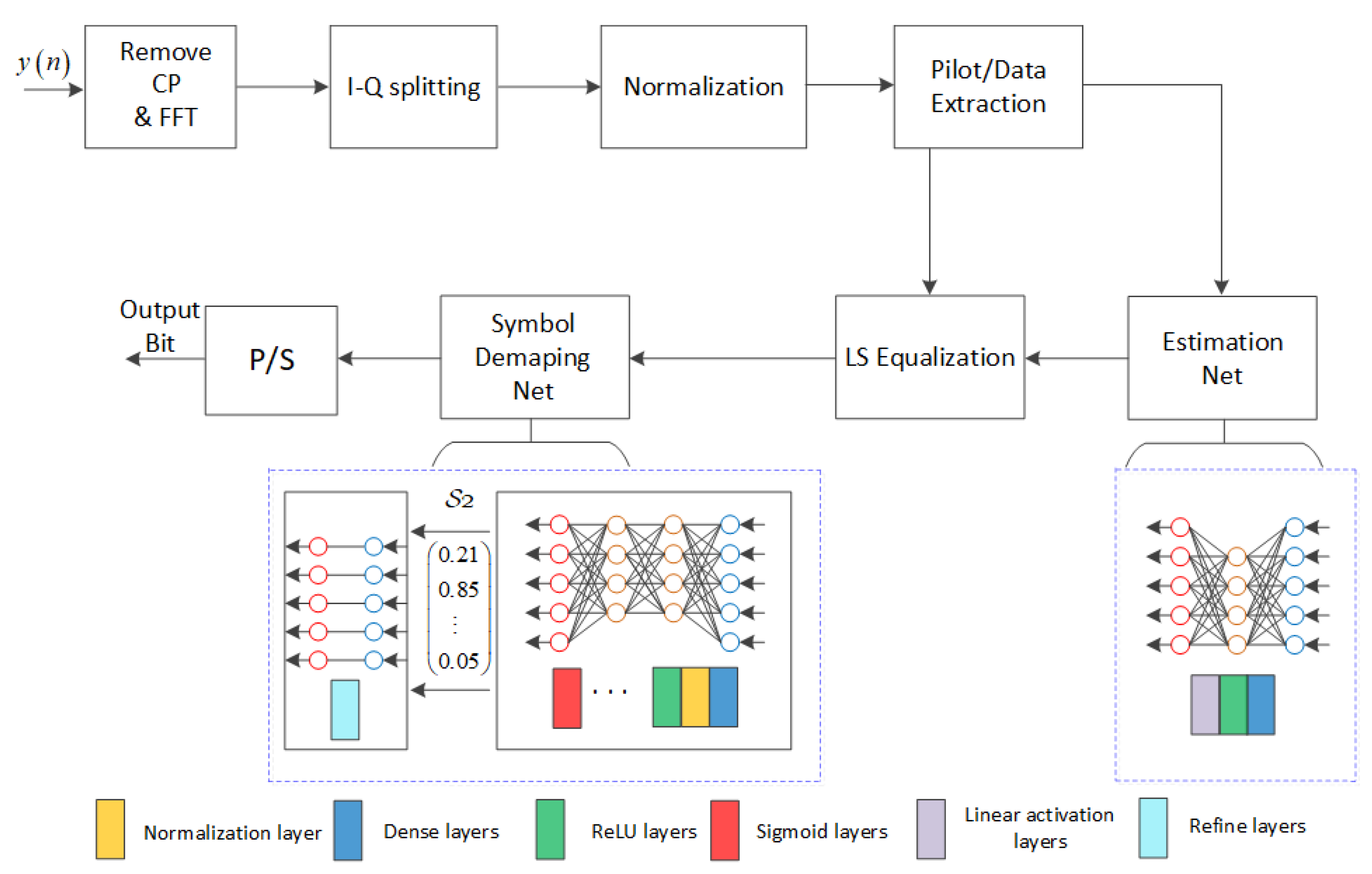
The diagram of the proposed DL-NPE for OFDM-based VLC system is shown in Figure 3. Compared with the conventional OFDM receiver in Figure 1, the DL-NPE replaces the traditional module, i.e., channel estimation and the constellation de-mapping, and employs two subnets, i.e., S 1 and S 2 , for channel impairment compensation and symbol detection, respectively. Note that the network S 1 is composed by the cascaded sub-layer block including dense layer and activation function. As for S 2 , it is made up by a cascaded sub-layer block containing dense layer, a normalization layer, and an activation function. In addition, different amounts of neurons can be used in different dense layers for both S 1 and S 2 . Furthermore, the proposed scheme incorporates the traditional solution of the channel estimation and symbol detection algorithm into the system architecture.
After CP removal, FFT calculation, and symmetric data removal, the time domain receiving y is transformed into the frequency domain Y . Since Y is the complex symbol and cannot be directly used for the NN input, the real and imaginary parts of Y should be split first and reformatted in a new symbol Y ¯ M , where M = 2 N 1 . In order to improve the convergence rate and the generalization ability of the DL-NPE, the min–max normalization is utilized to pretreat the Y ¯ , shown as follows:
Y ¯ = Y ¯ min Y ¯ max Y ¯ min Y ¯ .
During the training phase, the pilots are deployed in the first OFDM block within one frame of training set, and the remaining are used for the transmitted data. Based on this mapping, the distorted pilots Y p and useful data Y d can be easily extracted from Y ¯ . Instead of using a DNN to estimate the original data straightforwardly [29], the Y p and X p are first fed into the S 1 network for noise reduction and roughly estimating the channel state information. Assume that S 1 employs L 1 layers in FC-DNN. As for the first dense layer, let D 1 S 1 denote the number of neurons and t 1 S 1 M be the layer input. Then, the corresponding output can be expressed as follows:
h 1 S 1 = W 1 S 1 t 1 S 1 + b 1 S 1 ,
where W 1 S 1 D 1 S 1 × M and b 1 S 1 D 1 S 1 are the weight matrix and bias vector, respectively. Then, h 1 S 1 is fed into the activation function to improve the expression ability of S 1 to the true CIR. Note that the Relu function ρ R L is employed as the activation function for most layers. However, beyond that, the linear activation function is deployed in the last layer due to the main goal of S 1 being to learn the true CIR from the pilot symbols. In addition, the neuron number of the last layer should be set as M so that the dimension of final output of S 1 can keep consistent with that of the pilot. After an efficient learning, the estimated CIR h ^ can be obtained at the output of S 1 . Then, the data symbol can be roughly compensated within the compensation module using the traditional least-square (LS) solution, shown as follows:
X ¯ = h ^ 1 Y d .
After that, we feed X ¯ M into S 2 for further refining the results of (12) while recovering the original symbols. Assume that S 2 employs FC-DNN and contains L 2 layers. As for the first layer of S 2 , let D 1 S 2 denote the number of neurons, t 1 S 2 M is the layer input, and W 1 S 2 D 1 S 2 × M and b 1 S 2 D 1 S 2 are the weight matrix and bias vector, respectively. Then, the corresponding output h 1 S 2 can be similarly calculated using (11) and then passed through the normalization layer to keep the same distribution for the input of each sub-layer block. For simplicity, the Batch normalization is adopted and the outputs can be expressed as follows
h 1 S 2 B N = α 1 S 2 h 1 S 2 E h 1 S 2 σ h 1 S 2 2 + ϵ + β 1 S 2 ,
where B N denotes the Batch normalization function, and α 1 S 2 and β 1 S 2 are the scaling and shift factors, respectively. In order to prevent the denominator from being zero, a constant ϵ approaching zero is always added in the denominator term. Then, the h 1 S 2 B N is fed into ρ R L to make the data features nonlinear. However, the logistic Sigmoid function ρ s i g is employed as the activation function for the last dense layer. The reason is that the main goal of S 2 is to recover the original binary data; nevertheless, the logistic Sigmoid activation functions is very convenient for mapping the input values to the 0 , 1 range. Finally, the output of the last dense layer can be expressed by the following:
t ^ = ρ s i g W L 2 S 2 t L 2 S 2 + b L 2 S 2 B N ,
where t ^ P is the bit vector, P = N 1 log 2 Q , and Q denotes the modulation level. However, the output of the Sigmoid fluctuates in a certain range due to the influence of noise. In order to refine the coarse output, t ^ is sent into the refine layer to further improve the demodulation performance of original data. The refined bit stream t ^ 0 can be obtained as follows:
t ^ 0 = s g n t ^ 1 2 + s g n t ^ 1 2 2 ,
where s g n is the Signum function. Finally, the overall channel impairment can be mitigated and the original information can be recovered to the binary stream directly using the proposed S 1 and S 2 . As aforementioned, the proposed scheme combines the conventional signal processing algorithm and the DL approach together, which can achieve a relatively robust recovery performance under various scenarios.

3.2. Training Specification

Based on the IM/DD channel, the training set is obtained using a simulation under different system configurations in terms of training SNR, the CP usage, and the clipping effect. In each training epochs, 100 DCO-OFDM symbols are random generated and one of them is chosen to carry the pilots. After channel propagation, the received symbol and the original transmitted data are formed as the training set. In order to accelerate the network convergence rate, we should collect the diverse and abundant training set as much as possible, which are beneficial to the parameters learning. Note that the DC gain is removed from the training set so that we can evaluate the BER performance of the proposed scheme more fairly [31]. The full channel effect, which include the LED nonlinearity, multipath propagation of optical model, and the channel noise, is involved in the training procedure.
In the training phase, the proposed scheme is trained to optimize the equalization and demodulation performance by tuning the weights Θ = W S 1 , b S 1 , W S 2 , b S 2 so that the reconstructed t ^ 0 is closer to the original t . Therefore, we employ the mean squared error (MSE) between the original t and the estimated t ^ 0 as the training loss function, demonstrated by the following:
l o s s = t t ^ 0 2 2 .
The goal is to learn the optimized Θ ^ , which minimizes the objective MSE during each training epochs, shown as follows:
Θ ^ = arg min Θ t t ^ 0 2 2
Considering the computational efficiency and stability, the adaptive moment estimation (Adam) is used as the optimizer. Furthermore, the TensorFlow is adopted since it can easy implement and train the complex DL model on fast concurrent graphics processing unit (GPU) architectures. We train the DL model on a work station running with a GPU of NVIDIA GeForce 2080Ti driven by CUDA 10.0. As for the testing phase, each batch contain 100 DCO-OFDM symbols and 8000 batches are totally employed for each SNR values. Note that, the testing data should be set different from the training ones.

3.3. Complexity Analysis

With regard to the complexity of the proposed scheme, the S 1 and S 2 are dominant in the receiver. However, the computational complexity of the training stage is really hard to evaluate. We know that the DL network is always trained in offline ways. However, as long as the model is well-trained, it can be deployed with the optimized Θ ^ and the forward propagation is employed for signal calculation. Thus, only some additions and multipliers are needed in the testing stage. For simplicity, only the forward propagation is considered when quantifying the computational complexity. Considering that all of the hidden layers employ D neurons, the complexity of S 1 can be approximately expressed by O M D + L 1 2 D 2 . Similarly, the complexity of S 2 is denoted as O P D + L 2 2 D 2 .

4. Simulation Results

To show the feasibility of the proposed scheme in joint channel estimation and symbol detection, several simulations of the proposed scheme over the IM/DD channel are conducted under different training conditions to investigate the corresponding convergence and BER performance. For simplicity, the DCO-OFDM symbol containing total 128 subcarriers are employed, where the QPSK with Q = 4 are used as the modulation method. The CP with the ratio of 1 / 64 is adopted for mitigating ISI. In addition, we choose D C = 0.4 and f 0 = 20 MHz for a LED model in (4). For an empty room scenario, the indoor VLC channel following the model in [39] is used for training.
As can be seen from the above analysis, the S 1 network contains one hidden layer and the dimension of the input tensor is M , which is the combination of the real and imaginary parts for one DCO-OFDM symbol. As for the initialization, the input of S 1 can be set as the results of the traditional LS solution with the help of the arranged pilots, which improve the training speed to some extent. The S 2 network involves four layers with the neuron numbers of M , 256, 256, and P . At the end, the refine layer with the P Signum function is connected to further refine the data. It should be noted that the number of neurons in the input and output layers is determined by the subcarriers N and that of the output layer also depends on the modulation level Q . However, the number of neurons in the hidden layers is chosen based on an empirical trial. In the early training stages, the learning rate is fixed to a big value of 0.01 and then gradually decreased in the later training stage. The training specification and parameters of S 1 and S 2 are shown in Table 1.

4.1. The Convergence Performance

Choosing the appropriate training sets is very important in a DL training procedure since the channel noise within the training samples affects the learning ability and generalization ability of a customized DL model. Therefore, the favorable SNR of the training set should be investigated first; thus, both the S 1 and S 2 are trained under various training SNR λ .
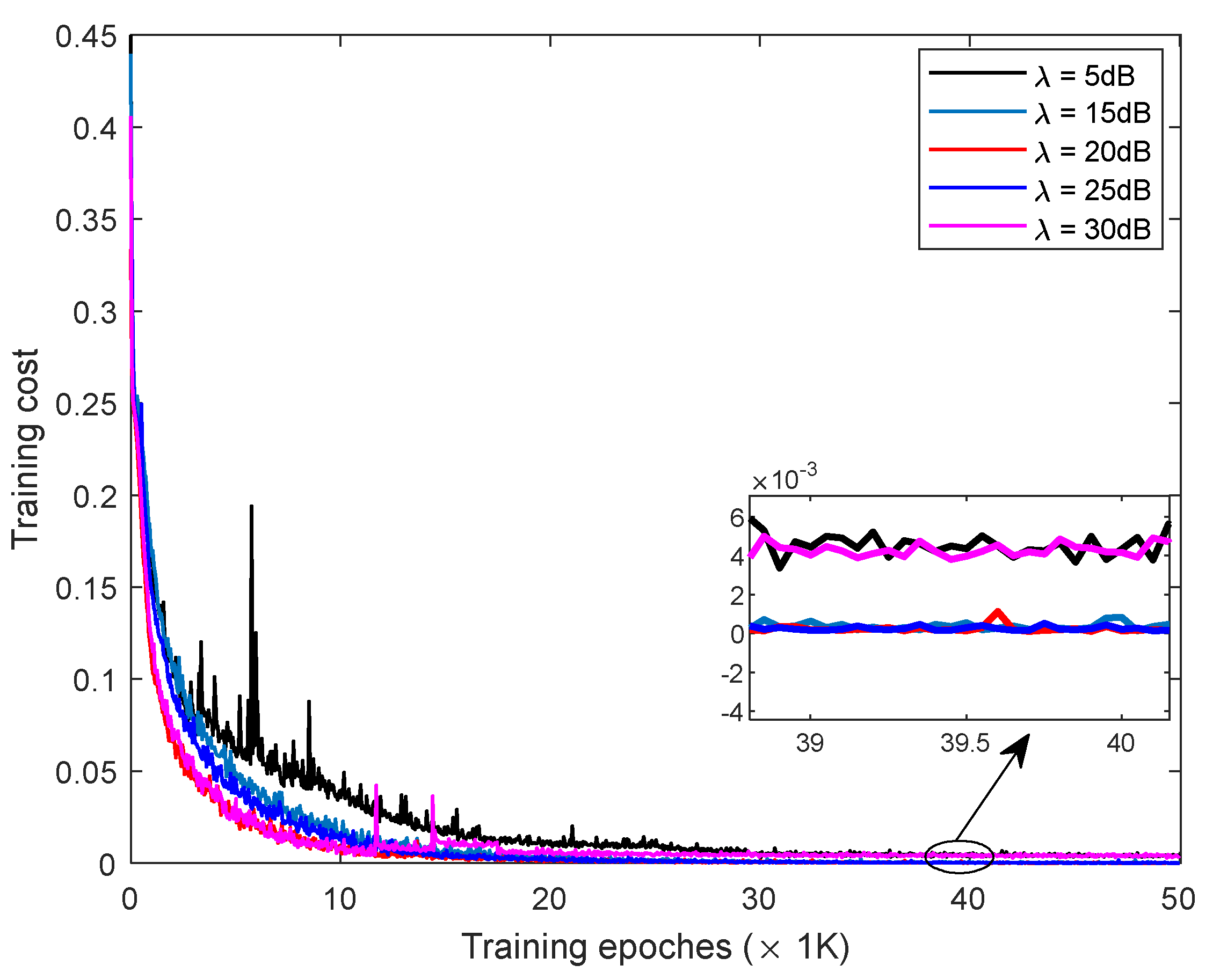
The training cost of the proposed scheme under the LOS link training is demonstrated in Figure 4, where the λ varies from 5 to 30 dB. In general, all of the five curves tend to be stable gradually as the training epoch increases. The final loss of the proposed scheme for λ = 5 dB remains around 0.005, which induces the barely satisfactory channel of learning and symbol detection. Moreover, we can find that the curve for λ = 30 dB has a similar final loss result with that of λ = 5 dB. The main reason is that the samples with high SNR reduce the learning ability of the DL model to channel noise. However, the final loss results for λ = 1 5 , 20, and 25 dB are about 1.79 × 10 4 , indicating excellent network training since it can meet the requirements of the symbol detection in QAM constellation. In addition, it can be also seen from the figure that the proposed scheme with a large λ converges faster than the one for a small λ , e.g., the curve with λ = 5 dB takes about 32,000 epochs to achieve convergence, whereas that for λ = 25 dB undergoes only 14,350 epochs.
The corresponding loss performance under the NLOS links for training are depicted in Figure 5. Similar conclusions can also be drawn to that of the LOS case. Although the corresponding convergence rate is slightly degraded compared with the one for the LOS case, it still can achieve the final stable state. However, the loss curve for λ = 5 dB has an apparent fluctuation when it undergoes 35,000 epochs. Generally, the training SNR, which can affect the convergence performance of the proposed scheme to a certain extent, is not as big. Therefore, the size of the required training overheads could be reduced significantly and the learning ability of the proposed scheme can be improved by selecting proper training sets.

4.2. The BER Performance

The BER performance of the proposed scheme based on different training SNRs are investigated in this section under the LOS and NLOS conditions, respectively. For simplicity, only the special optical links in terms of one LOS and three NLOS links are adopted in the testing stage to evaluate the system performance. For convenience, the three NLOS links with the root mean square (RMS) delaying the spread by 7.92, 8.2, and 8.9 ns are marked as U 1 , 5 , U 1 , 1 , and U 2 , 1 , respectively. In addition, the BER of the original received signal and the ideal equalized signal are also depicted here for the convenience of comparison. Note that the original case does not have any equalization, and the ideal case has the CSI perfectly known to a receiver that employs a zero-forcing (ZF) equalizer.
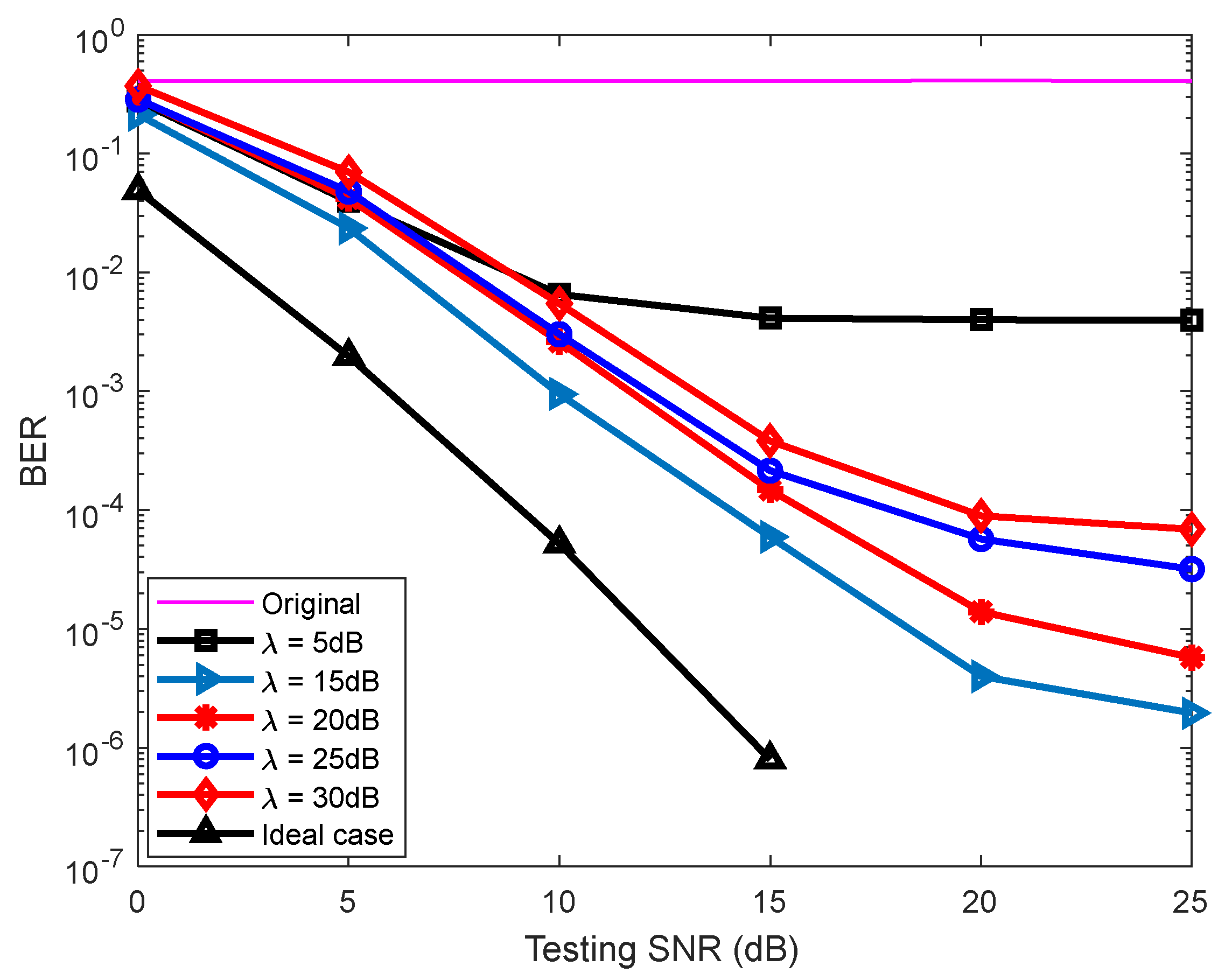
Figure 6 shows the BER performance comparison of the proposed DL-NPE over a LOS link with different λ . In general, we can observe from the figure that all of the BER curves have obvious performance improvements compared with the original case and can achieve an acceptable target BER of less than 1 × 10 3 . Nevertheless, the proposed scheme for λ = 5 and 30 dB can achieve similar BERs because they both converge to a similar loss in the training procedure. In addition, the BER curves of these two curves seem to be saturated when the testing SNR is above 20 dB. However, they still have the ability to reduce the BER with increasing testing SNR since the corresponding value is lower than 5.2 × 10 4 . Comparatively speaking, the proposed scheme for λ = 15 dB can provide the best BER performance, and the required power can be reduced by at least 2 dB compared with that of λ = 20 and 25 dB for the same BER level. If the DL-NPE was trained with a small noise level, the model only learns the small decision region near the original symbol location in the constellation plane, which is unfavorable for the learning of signal demapping. Note that the BER performance reaches the performance floor at high SNR levels, and the main reason is that the DL-NPE configured with this parameter reached their maximum performance capacity; thus, there is still residual nonlinear noise in the equalized signal. Although the BER curve for λ = 15 dB is not exactly the same as the ideal case, the power gap is small, e.g., 1.9 dB for a BER of 1 × 10 4 , which indicates that the overall channel nonlinearity can be compensated efficiently to a certain degree because the CSI of the IM/DD channel can be approximately learned by the DL approach from the training data.
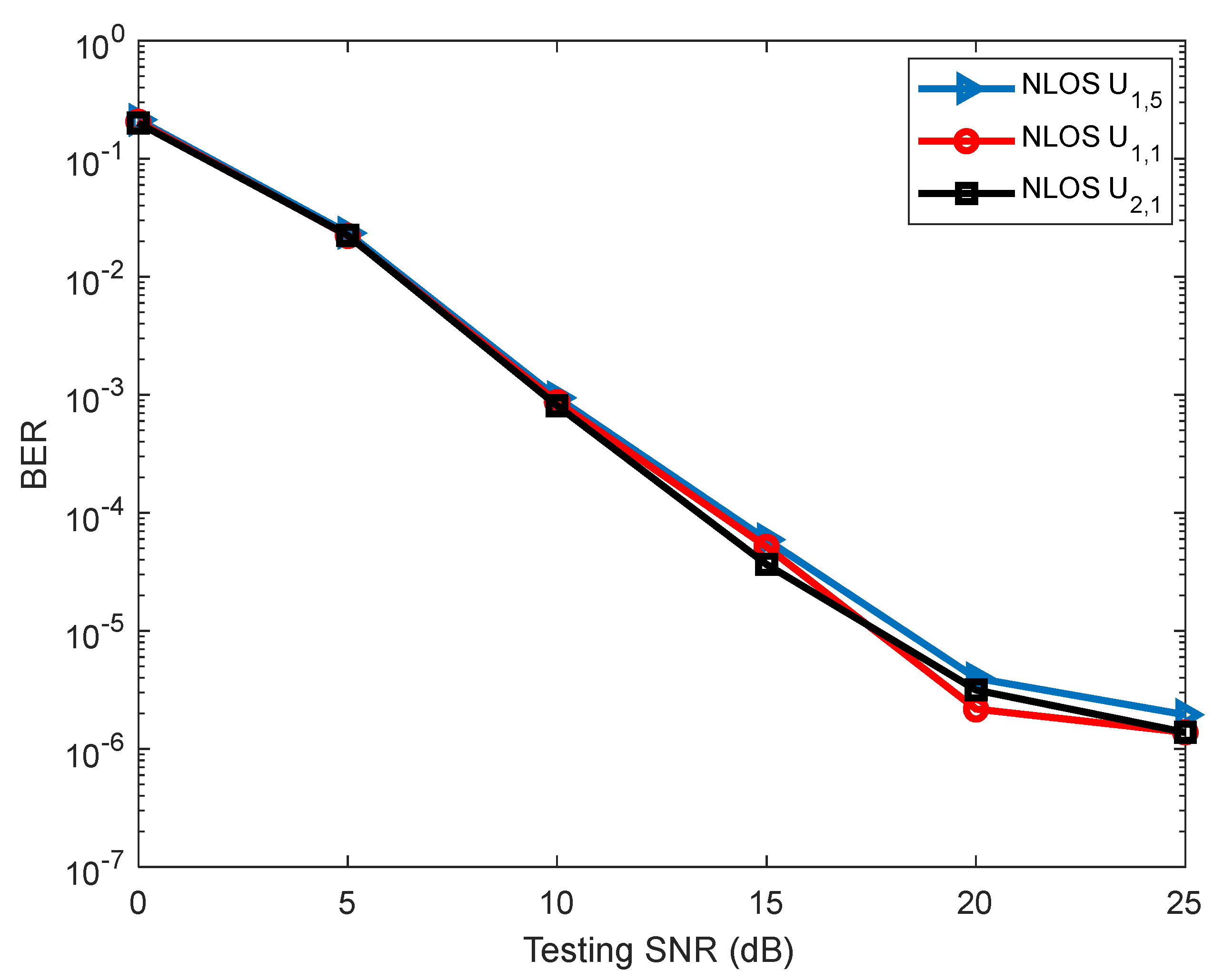
Figure 7 demonstrates the corresponding BERs for different λ under the NLOS case U 1 , 5 . As seen from the figure, the proposed scheme can still provide acceptable equalization as λ varied from 15 to 30 dB. Note the fact that the performance of the scheme with λ = 30 dB is improved compared with the results in Figure 6, whereas the others are degraded to a slight degree. This special phenomenon can be explained by the corresponding training loss shown in Figure 5. Moreover, as for a BER of 1 × 10 4 , the proposed scheme with λ = 15 dB can save the required power by 1.3 dB and 3.5 dB compared with that of λ = 20 and 25 dB, respectively. In addition, the well-trained model for λ = 15 dB is also evaluated under the NLOS U 1 , 1 and U 2 , 1 , and the corresponding results are shown in Figure 8. Clearly seen from the figure, the BER performance of these three cases are very similar for low SNRs and only have a slight difference at high SNRs, which indicates that the proposed scheme has robust equalization performance.
Combing the convergence performance shown in Figure 4 and Figure 5, although the proposed model trained at λ = 25 dB has relative fast convergence speed, it achieves a suboptimal BER compared with that of λ = 15 and 20 dB. This just shows the fact that the proposed scheme does not necessarily have robust generalization ability even if it has an excellent learning ability. This shows that we cannot select the learned DL model just only based on their learning ability. The optimal learned model should be the optimal trade-offs between the learning and the generalization ability. Under the consideration of convergence speed and training quality, the trained model with λ = 15 dB is employed in the following.

4.3. Impact of CP

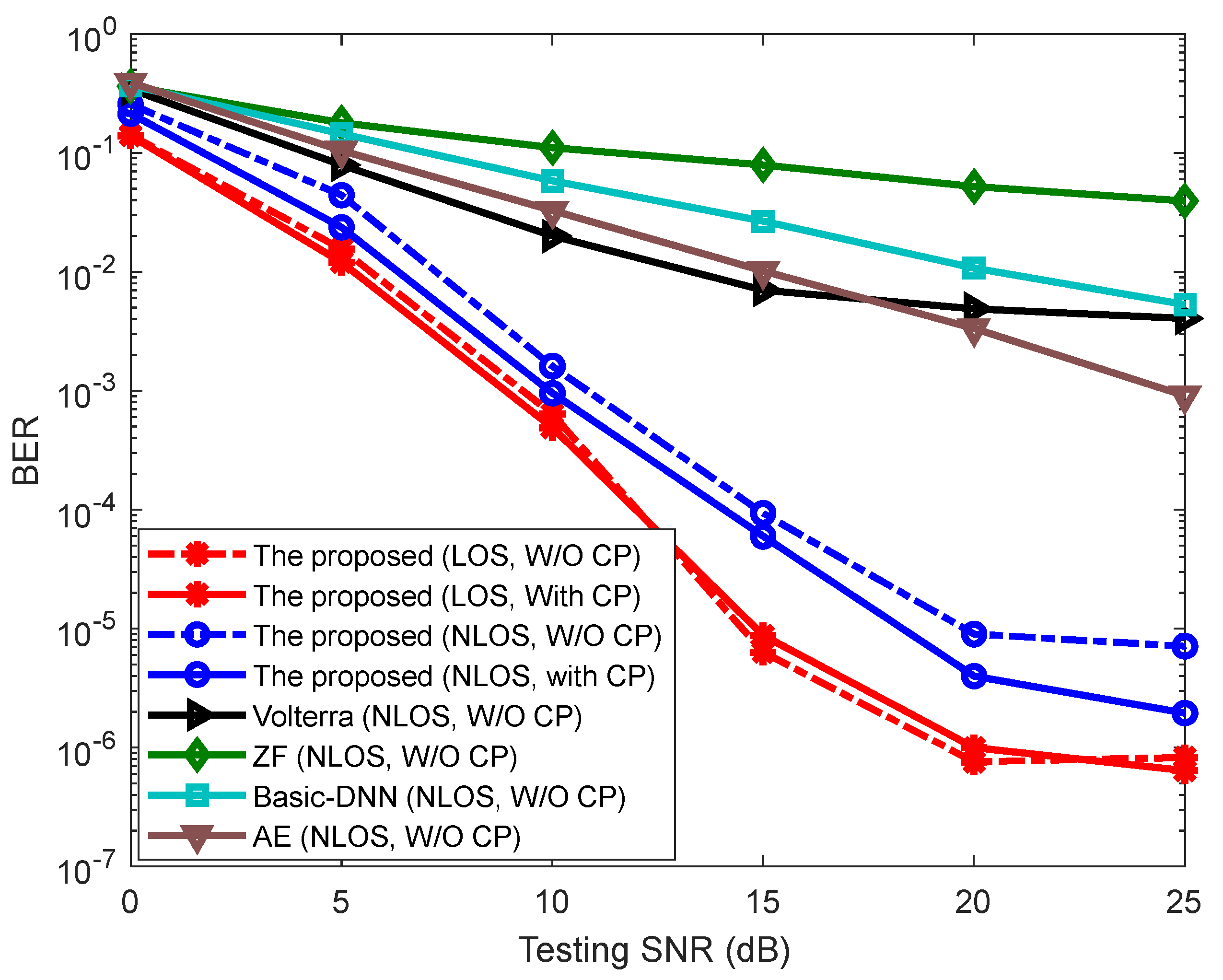
The CP used in OFDM systems can mitigate the ISI caused by optical multipath channels, but it degrades transmission efficiency and costs time and energy. As in the conditions of with-CP and CP-removal DCO-OFDM, the BER of the proposed scheme over LOS and NLOS U 1 , 5 are compared in Figure 9. In addition, as for the CP-removal NLOS case, the other four competitive approaches, in terms of the traditional ZF equalization with 32 comb-pilots, the Volterra equalizer based on recursive prediction error method (RPEM), the basic DNN with one hidden layer, and the AE based on two DNN, are also implemented for convenient analysis and comparison.
As for the other four competitive approaches, they suffer serious ISI from the diffuse optical channel in the case of CP removal, leading to severe BER performance degradation. However, for the LOS channel, the BER of the proposed scheme with CP is almost the same as the one without CP. As for NLOS U 1 , 5 , the BER is slightly decreased when the CP is omitted, but they still have high similarity. In general, compared with the traditional ZF and the Volterra equalizer, the proposed scheme can work well in resolving ISI even under the CP removal condition from the BER investigation of LOS and NLOS. Furthermore, it can still provide an excellent equalization performance, which indicates that the characteristics of IM/DD channel have been learned in the training stage by the proposed scheme. This mainly benefits from the fact that the DNN has a powerful self-study ability. Moreover, we can also infer that the selected model has good adaptability and generalization ability when the conditions of online deployment do not exactly agree with that of the training stage.

4.4. Impact of Clipping

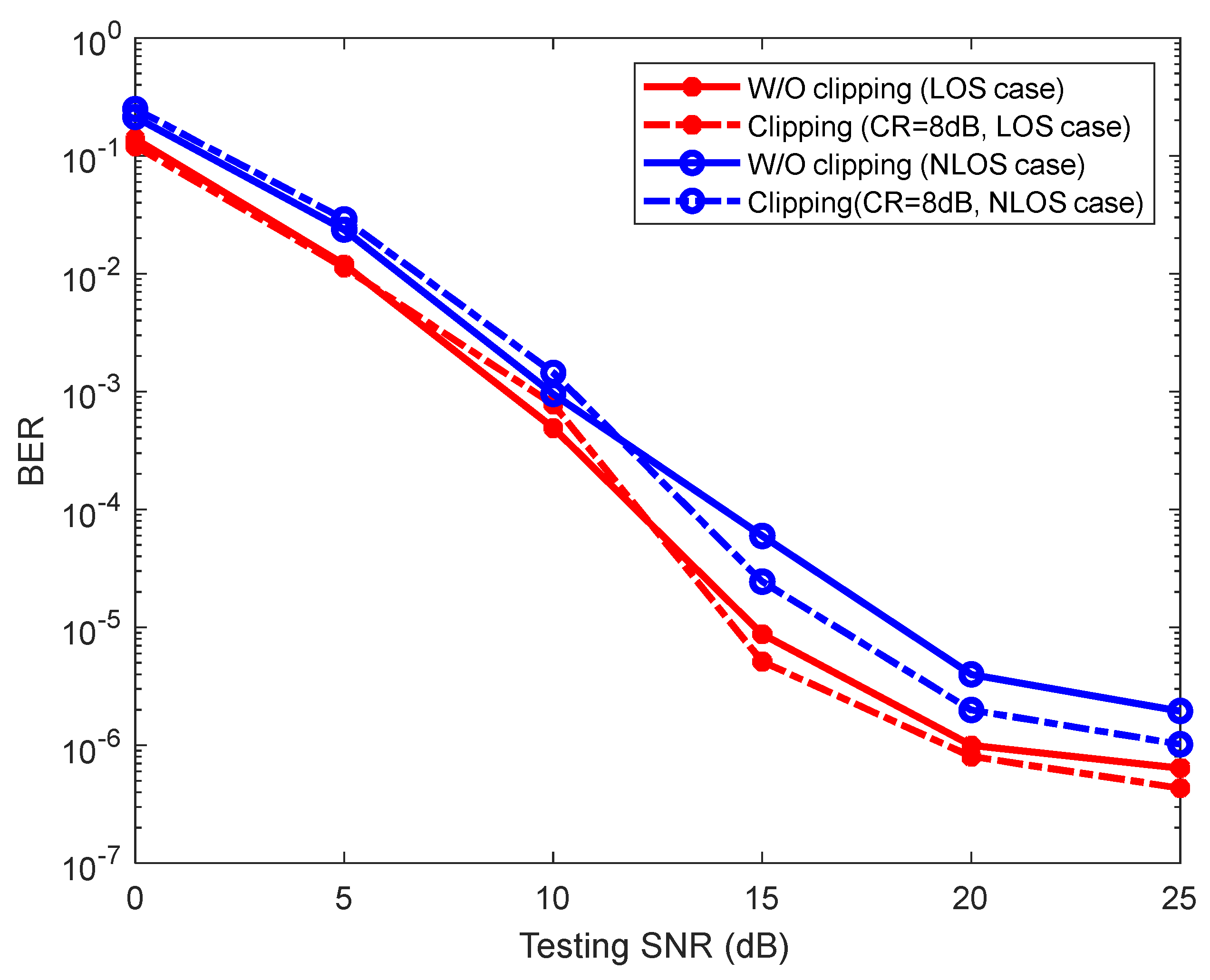
As aforementioned in the previous section, the high PAPR of DCO-OFDM leads more LED nonlinearity, thus drastically deteriorating the overall system performance. Clipping is favorable in LED non-linearity mitigation, which is an easy and simple approach and can be directly employed in time-domain DCO-OFDM signal. Nonetheless, the noise is accompanied by deep clipping, which deteriorates the BER performance and corrupts the signal spectrum. Figure 10 depicts the BER curves of the proposed scheme over LOS and NLOS U 1 , 5 when the clipping with CR = 8 dB is applied. When the tested SNR is greater than 10 dB, the advantage brought by clipping is dominant in the system compared with the disadvantage brought by the accompanied clipping noise because an appropriate clipping can relieve the nonlinear distortion caused by the LED. Therefore, the proposed scheme is more robust to the nonlinear clipping noise. The reason for the superior performance is that the clipping procedure is similar to the upper saturation effect of LEDs so that the characteristics of the nonlinear clipping can be also learned in the training stage, which suggests the robustness of the proposed scheme against nonlinear clipping distortions while the system could enjoy the benefits of clipping.
In summary, we can conclude that the proposed DL-NPE is beneficial to the channel impairment compensation and can achieve excellent BER performance improvement from the above simulations and discussions.

5. Conclusions

We demonstrate the architecture of the proposed model-driven DL-NPE for joint channel estimation and symbol detection in a VLC system. The simulation results show that the overall channel impairment of the IM/DD channel can be effectively compensate and the distorted symbols are demodulated to the bit stream efficiently, which show the unique benefits of the proposed scheme in feature learning of channel characteristics and the constellation de-mapping relationship. Moreover, it can still work effectively as the VLC system is complicated by serious distortions and interference, which proves the robustness and generalization ability of the proposed scheme. Nonetheless, it is quite important to collect the accurate and effective training data as much as possible and to select the appropriate well-trained DL-NPE from the perspective of balancing the learning and generalization abilities since the online deployment in practical scenario may be different from that in the training stage. In addition, the training accuracy also depends on the weight initialization of the network. A more rigorous analysis to optimize the proposed model for better performance is left for future work.

Author Contributions

Conceptualization, P.M. and W.Y.; methodology, P.M. and Y.Y.; software, P.M. and W.Y.; validation, W.Y. and H.P.; writing, P.M.; writing—review and editing, P.M. and H.P.; grammar check, H.P.; funding acquisition, P.M. and Y.Y. All authors have read and agreed to the published version of the manuscript.

Funding

This work is supported by the National Natural Science Foundation of China (NSFC) under grants 61801257 and 61761019, by the Shandong Provincial Natural Science Foundation under grant ZR2019BF001, and by the China Postdoctoral Science Foundation under grant 2019M652322. The APC was funded by NSFC, grant 61801257.

Institutional Review Board Statement

Not applicable.

Informed Consent Statement

Not applicable.

Data Availability Statement

The data presented in this study are available from the first author upon request.

Acknowledgments

The authors express their gratitude to the editors and the anonymous reviewers for their insightful suggestions and general assistance.

Conflicts of Interest

The authors declare no conflict of interest.

References

  1. Jia, L.; Shu, F.; Chen, M.; Zhang, J.; Wang, J. Joint constellation-labeling optimization for VLC-CSK systems. IEEE Wireless Commun. Lett. 2019, 8, 1280–1284. [Google Scholar] [CrossRef] [Green Version]
  2. Jia, L.; Shu, F.; Huang, N.; Chen, M.; Wang, J. Capacity and Optimum Signal Constellations for VLC Systems. J. Lightwave Technol. 2020, 38, 2180–2189. [Google Scholar] [CrossRef] [Green Version]
  3. Dai, L.; Fang, Y.; Yang, Z.; Chen, P.; Li, Y. Protograph LDPC-Coded BICM-ID with Irregular CSK Mapping in Visible Light Communication Systems. IEEE Trans. Veh. Technol. 2021, 70, 11033–11038. [Google Scholar] [CrossRef]
  4. Chen, C.; Nie, Y.; Liu, M.; Du, Y.; Liu, R.; Wei, Z.; Fu, H.Y.; Zhu, B. Digital Pre-Equalization for OFDM-Based VLC Systems: Centralized or Distributed? IEEE Photonics Technol. Lett. 2021, 33, 1081–1084. [Google Scholar] [CrossRef]
  5. Chen, S.; Liang, Y.; Sun, S.; Kang, S.; Cheng, W.; Peng, M. Vision, requirements, and technology trend of 6G: How to tackle the challenges of system coverage, capacity, user data-rate and movement speed. IEEE Wireless Commun. 2020, 27, 218–228. [Google Scholar] [CrossRef] [Green Version]
  6. Wang, J.; Liu, C.; Wang, J.; Wu, Y.; Lin, M.; Cheng, J. Physical layer security for indoor visible light communications: Secrecy capacity analysis. IEEE Trans. Commun. 2018, 66, 6423–6436. [Google Scholar] [CrossRef] [Green Version]
  7. Huang, N.; Wang, X.; Chen, M. Transceiver design for MIMO VLC systems with integer-forcing receivers. IEEE J. Sel. Areas Commun. 2018, 36, 66–77. [Google Scholar] [CrossRef]
  8. Miao, P.; Qi, C.; Fang, L.; Song, K.; Bu, Q. Deep clipping noise mitigation using ISTA with the specified observations for LED-based DCO-OFDM system. IET Commun. 2018, 12, 2582–2591. [Google Scholar] [CrossRef]
  9. Deng, L.; Fan, Y.; Zhao, Q. A novel PAPR reduction scheme for VLC DCO-OFDM systems. Opt. Commun. 2018, 426, 164–169. [Google Scholar] [CrossRef]
  10. Jawhar, Y.A.; Audah, L.; Taher, M.A.; Ramli, K.N.; Mohd, N.S.S.; Musa, M.; Ahmed, M.S. A review of partial transmit sequence for PAPR reduction in the OFDM systems. IEEE Access 2019, 7, 18021–18041. [Google Scholar] [CrossRef]
  11. Chen, H.; Chung, K.-C. A PTS technique with non-disjoint sub-block partitions in M-QAM OFDM systems. IEEE Trans. Broadcast. 2018, 64, 146–152. [Google Scholar] [CrossRef]
  12. Hou, J.; Zhao, X.; Gong, F.; Hui, F.; Ge, J. PAPR and PICR reduction of OFDM signals with clipping noise-based tone injection scheme. IEEE Trans. Veh. Technol. 2017, 66, 222–232. [Google Scholar] [CrossRef]
  13. Lu, H.; Jin, J.; Wang, J. Alleviation of LED nonlinearity impact in visible light communication using companding and predistortion. IET Commun. 2019, 13, 818–821. [Google Scholar] [CrossRef]
  14. Elgala, H.; Mesleh, R.; Haas, H. Non-linearity effects and predistortion in optical OFDM wireless transmission using LEDs. Int. J. Ultra Wideband Commun. Syst. 2009, 1, 143–150. [Google Scholar] [CrossRef]
  15. Mitra, R.; Bhatia, V. Low complexity post-distorter for visible light communications. IEEE Commun. Lett. 2017, 21, 1977–1980. [Google Scholar] [CrossRef]
  16. Miao, P.; Chen, G.; Wang, X.; Yao, Y.; Chambers, J.A. Adaptive Nonlinear Equalization Combining Sparse Bayesian Learning and Kalman Filtering for Visible Light Communications. J. Lightwave Technol. 2020, 38, 6732–6745. [Google Scholar] [CrossRef]
  17. Mitra, R.; Bhatia, V. Unsupervised multistage-clustering-based hammerstein postdistortion for VLC. IEEE Photon. J. 2016, 9, 1–10. [Google Scholar] [CrossRef]
  18. Jain, S.; Mitra, R.; Bhatia, V. KLMS-DFE based adaptive post-distorter for visible light communication. Opt. Commun. 2019, 451, 353–360. [Google Scholar] [CrossRef]
  19. Tan, J.; Wang, Z.; Wang, Q.; Dai, L. BICM-ID scheme for clipped DCO-OFDM in visible light communications. Opt. Express 2016, 24, 4573–4581. [Google Scholar] [CrossRef] [PubMed] [Green Version]
  20. Chi, N.; Jia, J.; Hu, F.; Zhao, Y.; Zou, P. Challenges and Prospects of Machine Learning in Visible Light Communication. J. Commun. Inform. Netw. 2020, 5, 302–309. [Google Scholar]
  21. Mitra, R.; Bhatia, V.; Jain, S. Performance Analysis of Random Fourier Features Based Unsupervised Multistage-Clustering for VLC. IEEE Wireless Commun. Lett. 2021, 25, 2659–2663. [Google Scholar] [CrossRef]
  22. Khan, F.N.; Lu, C.; Lau, A.P.T. Machine learning methods for optical communication systems. In Proceedings of the Signal Processing in Photonic Communications, Washington, DC, USA, 15 July 2017. [Google Scholar]
  23. Lu, X.; Wang, K.; Qiao, L.; Zhou, W.; Wang, Y.; Chi, N. Nonlinear compensation of multi-CAP VLC system employing clustering algorithm based perception decision. IEEE Photon. J. 2017, 9, 1–9. [Google Scholar] [CrossRef]
  24. Pham, T.L.; Shahjalal, M.; Bui, V.; Jang, Y. Deep Learning for Optical Vehicular Communication. IEEE Access 2020, 8, 102691–102708. [Google Scholar] [CrossRef]
  25. He, Y.; Jiang, M.; Ling, X.; Zhao, C. Robust BICM design for the LDPC coded DCO-OFDM: A deep learning approach. IEEE Trans Commun. 2019, 68, 713–727. [Google Scholar] [CrossRef]
  26. He, H.; Jin, S.; Wen, C.K.; Gao, F.; Li, G.Y.; Xu, Z. Model-driven deep learning for physical layer communications. IEEE Wireless Commun. 2019, 26, 77–83. [Google Scholar] [CrossRef] [Green Version]
  27. Wen, C.K.; Shih, W.T.; Jin, S. Deep Learning for Massive MIMO CSI Feedback. IEEE Wireless Commun. Lett. 2018, 7, 748–751. [Google Scholar] [CrossRef] [Green Version]
  28. Li, X.; Zhao, C.; Jiang, M. Neural network for demodulating the output signals of nonlinear systems with memory. In Proceedings of the 2017 9th IEEE International Conference on Wireless Communications and Signal Processing (WCSP), Nanjing, China, 23 October 2017; pp. 1–5. [Google Scholar]
  29. Ye, H.; Li, G.Y.; Juang, B.H. Power of deep learning for channel estimation and signal detection in OFDM systems. IEEE Wireless Commun. 2018, 7, 114–117. [Google Scholar] [CrossRef]
  30. Gao, X.; Jin, S.; Wen, C.K.; Li, G.Y. ComNet: Combination of deep learning and expert knowledge in OFDM receivers. IEEE Wireless Commun. 2018, 22, 2627–2630. [Google Scholar] [CrossRef] [Green Version]
  31. Miao, P.; Yin, W.; Peng, H.; Yao, Y. Deep Learning based Nonlinear Equalization for DCO-OFDM Systems. In Proceedings of the IEEE International Conference on Electrical Engineering and Mechatronics Technology, Qingdao, China, 2 July 2021; pp. 699–703. [Google Scholar]
  32. Ye, H.; Liang, L.; Li, G.Y.; Juang, B. Deep Learning-Based End-to-End Wireless Communication Systems with Conditional GANs as Unknown Channels. IEEE Trans. Wireless Commun. 2020, 19, 3133–3143. [Google Scholar] [CrossRef] [Green Version]
  33. Bai, Q.; Wang, J.; Zhang, Y.; Song, J. Deep Learning-Based Channel Estimation Algorithm Over Time Selective Fading Channels. IEEE Trans. Cogn. Commun. Netw. 2020, 6, 125–134. [Google Scholar] [CrossRef] [Green Version]
  34. Lee, H.; Lee, I.; Lee, H.S. Deep learning based transceiver design for multi-colored VLC systems. Opt. Express 2018, 26, 6222–6238. [Google Scholar] [CrossRef] [PubMed]
  35. Lee, H.; Lee, I.; Quek, T.Q.S.; Lee, H.S. Binary signaling design for visible light communication: A deep learning framework Visible Light Communication Using Deep Learning Techniques. Opt. Express 2018, 26, 18131–18142. [Google Scholar] [CrossRef] [PubMed]
  36. Miao, P.; Zhu, B.; Qi, C.; Jin, Y.; Lin, C. A model-driven deep learning method for LED nonlinearity mitigation in OFDM-based optical communications. IEEE Access 2019, 7, 71436–71446. [Google Scholar] [CrossRef]
  37. Hao, L.; Wang, D.; Cheng, W.; Li, J.; Ma, A. Performance enhancement of ACO-OFDM-based VLC systems using a hybrid autoencoder scheme. Opt. Commun. 2019, 442, 110–116. [Google Scholar] [CrossRef]
  38. Ulkar, M.G.; Baykas, T.; Pusane, A.E. VLCnet: Deep learning based end-to-end visible light communication system. J. Lightwave Technol. 2020, 38, 5937–5948. [Google Scholar] [CrossRef]
  39. Uysal, M.; Miramirkhani, F.; Narmanlioglu, O.; Baykas, T.; Panayirci, E. IEEE 802.15. 7r1 reference channel models for visible light communications. IEEE Commun. Mag. 2017, 55, 212–217. [Google Scholar] [CrossRef]
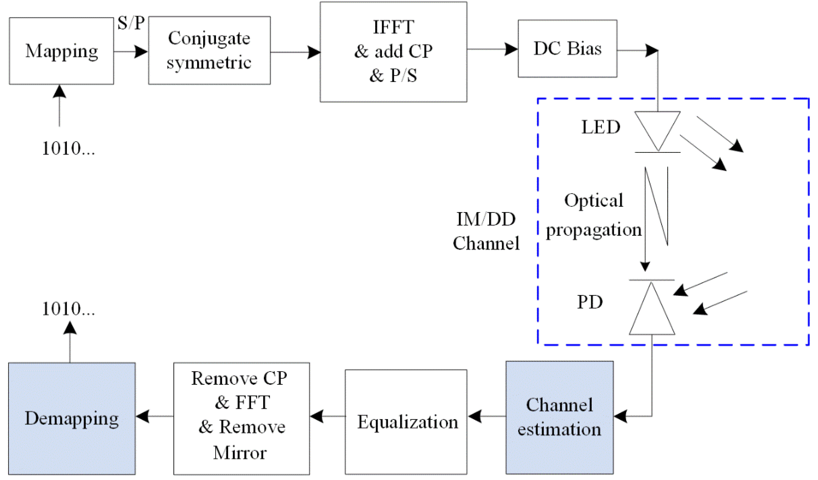
Figure 1. Block diagram of the DCO-OFDM system with an IM/DD channel.
Photonics 08 00453 g001
Figure 2. The memory effect of the channel impairments involving in the received signal.
Photonics 08 00453 g002
Figure 3. Diagram of the proposed DL-NPE scheme for the OFDM-based VLC receiver.
Photonics 08 00453 g003
Figure 4. The cost performance comparison for different training SNRs under the LOS case.
Photonics 08 00453 g004
Figure 5. The cost performance comparison for different training SNRs under the NLOS case.
Photonics 08 00453 g005
Figure 6. BER performance comparison of the proposed scheme under the LOS case.
Photonics 08 00453 g006
Figure 7. BER performance comparison of the proposed scheme under the NLOS U 1 , 5 .
Photonics 08 00453 g007
Figure 8. BER performance comparison of the proposed scheme under different NLOS cases.
Photonics 08 00453 g008
Figure 9. BER performance of the proposed scheme with/without CP.
Photonics 08 00453 g009
Figure 10. BER performance of the proposed scheme under clipping conditions.
Photonics 08 00453 g010
Table 1. Parameters and training of the proposed DL-NPE.
ParametersValues
Dimensions for S 1
Input M
Dense (ReLU)256
Dense (Linear) M
Dimensions for S 2
Input M
Dense (ReLU)256
Dense (ReLU)256
Dense (Sigmod) P
Refinesignum function
Training and Testing
OptimizerAdam
Learning Rate0.0001~0.01
Publisher’s Note: MDPI stays neutral with regard to jurisdictional claims in published maps and institutional affiliations.