Article

Coupled Chiral Optical Tamm States in Cholesteric Liquid Crystals

by
Maxim V. Pyatnov
1,*,
Ivan V. Timofeev
1,2,
Stepan Ya. Vetrov
1,2 and
Natalya V. Rudakova
1
1
Siberian Federal University, Institute of Engineering Physics and Radio Electronics, 660041 Krasnoyarsk, Russia
2
Kirensky Institute of Physics, Federal Research Center “Krasnoyarsk Scientific Center, Russian Academy of Sciences, Siberian Branch”, 660036 Krasnoyarsk, Russia
*
Author to whom correspondence should be addressed.
Photonics 2018, 5(4), 30; https://doi.org/10.3390/photonics5040030
Submission received: 29 August 2018 / Revised: 21 September 2018 / Accepted: 26 September 2018 / Published: 28 September 2018
(This article belongs to the Special Issue Nonlinear Dielectric Photonics and Metasurfaces)

Abstract

:
The modes formed by two coupled chiral optical Tamm states localized at the interfaces between a photonic cholesteric liquid crystal conjugated with polarization-preserving anisotropic mirrors have been analytically and numerically investigated. These modes are only excited at the diffracting polarization of incident light. As the cholesteric layer thickness decreases, the spectral splitting of the localized state frequency is predicted. The splitting value depends on the crystal layer thickness. At the nondiffracting circular polarization, the localized modes are not excited, and the system becomes similar to the Fabry–Pérot cavity containing an anisotropic helical structure.

Graphical Abstract

1. Introduction

The optical Tamm state (OTS) particularly attracts the attention of researches among various surface localized optical states. This is a mode localized at the interface between two highly reflecting media, which exponentially decays to both of them. Two photonic crystal media having overlapping band gaps can act as such media [1,2]. The existence of surface states in this case is a consequence of the fact that a photonic crystal can act as a medium with negative permittivity and permeability [3]. The field decay inside the photonic crystal is caused by the Bragg reflection condition. Such a localized mode at the interface between two materials can be excited by both TE and TM linear polarizations at any light incidence angle. The OTS manifests itself in experiments as a narrow resonance in the transmittance or reflectance spectrum of the sample [1]. If one of the media is a metal, the OTS is called a Tamm plasmon [4]. The interest in the OTSs and Tamm plasmons is due to their possible applications in lasers and emitters [5,6,7,8], sensors [9,10], photovoltaic devices [11], etc. Recently, Cheng et. al. demonstrated a liquid crystal-tuned Tamm-plasmon resonance device [12].
The OTSs can be strongly coupled with each other or with resonances of a different nature, including cavity modes, exciton polaritons and surface plasmons [13,14,15,16,17]. Such hybrid modes are characterized by anticrossing of the resonances upon tuning a position of one of them.
It seems promising to use a soft material as a photonic material. Cholesteric liquid crystals (CLCs) are the well-proven elements of optical systems. These are birefringent materials with the chirality property. The alignment of extended CLC molecules is characterized by a continuously-rotating director. Similar to one-dimensional photonic crystals, cholesterics have a photonic band gap [18]. However, the position and width of their band gap can be easily changed using external factors. In contrast to scalar photonic-crystal materials or distributed Bragg reflectors, CLCs have only band gap at the normal incidence of light. This band gap only exists for light with the diffracting circular polarization coinciding with the twisting of a cholesteric helix. The circularly-polarized radiation of the opposite direction (nondiffracting polarization) is not reflected from such a structure.
In contrast to the case of metals or conventional dielectrics, the circularly-polarized radiation reflected from the CLC preserves the sign of its polarization handedness. Therefore, obtaining a Tamm plasmon localized between the CLC and metallic layer or the OTS localized between the CLC and distributed Bragg reflector is a challenging problem. It can be solved in two ways. The first way is to use an additional anisotropic layer, e.g., a quarter-wave phase plate [19,20], an oppositely-twisted CLC [21] or a planar anisotropic defect in the CLC [22]. In this case, however, the observed localized states are not called Tamm states. The other way is to use a polarization-preserving (handedness-preserving or chiral) mirror instead of a conventional one. These mirrors retain not only the handedness, but also the ellipticity magnitude upon reflection. The state at the polarization-preserving mirror-CLC interface was described in the low [23] and finite [24] anisotropy approximations of a cholesteric crystal and named a chiral OTS. The metasurfaces can have the properties of handedness-preserving mirrors [25].
In this work, we examine the coupling between two chiral OTSs localized at both CLC boundaries.

2. Model Description

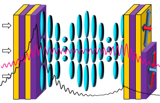
The system under study is presented in Figure 1. The right-handed CLC is sandwiched between two identical polarization-preserving anisotropic mirrors (PPAMs). The CLC parameters used in the simulation were ordinary and extraordinary refractive indices of n o = 1.54 and n e = 1.71 and a helix pitch of p = 0.4 μ m.These parameters are typical of the mixture of a Merck S-811 chiral additive and a nematic liquid crystal [26]. The CLC layer thickness is specified by parameter d. To meet the boundary conditions, we hereinafter assume the CLC to have an integer number of periods (the period is a distance of the director rotation by angle π ). The PPAMs consist of alternating uniaxial dielectric layers with refractive indices n e m and n o m . Each layer is rotated relative to the previous one by 90 . The mirrors contain N = 10 periods. The PPAM period thickness is 2 a = 0.2 μ m. As was shown previously, such anisotropic mirrors can preserve the polarization of the radiation falling onto them [27]. This is a necessary condition for forming the OTS at the CLC boundary. In [28], a chiral OTS was described at the CLC and PPAM interface. The angles between the CLC optical axes and adjacent mirror layers are hereinafter referred to as ψ and φ , respectively. Below, we assume ψ = π / 4 . The structure is surrounded by a medium with the refractive index equal to the averaged CLC refractive index n = ( n e + n o ) / 2 .
We assumed the refractive indices to be n e = n e m and n o = n o m ; i.e., the CLC refractive indices are equal to the corresponding refractive indices of the PPAM layers. At these parameters, the centers of the CLC and PPAM band gaps coincide. As was demonstrated in [23,24], under this condition at ψ = π / 4 , the OTS manifests itself in the spectrum exactly at the band gap center. At φ = ψ = π / 4 , the boundary conditions are satisfied, which leads to the possibility of exciting two OTSs localized at both boundaries of a confined CLC. Both OTSs are symmetric and therefore should appear in the spectrum at the same frequency; however, since these states are coupled through a finite CLC layer, the frequency degeneracy is eliminated, and two peaks arise in the spectrum at similar frequencies. At the integer number of CLC periods, the angle between the optical axes of the PPAM layers adjacent to the CLC from the left and right is φ + ψ = π / 2 . These layers are shown by different colors in Figure 1.

3. Results and Discussion

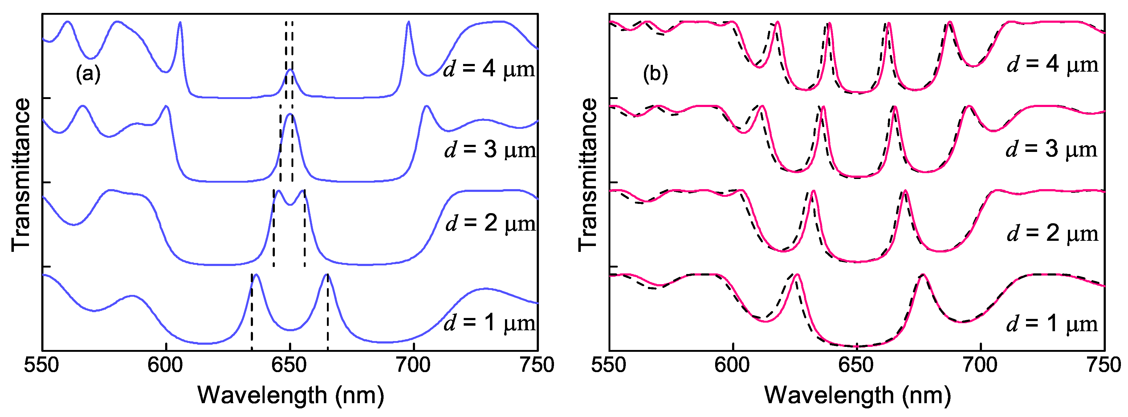
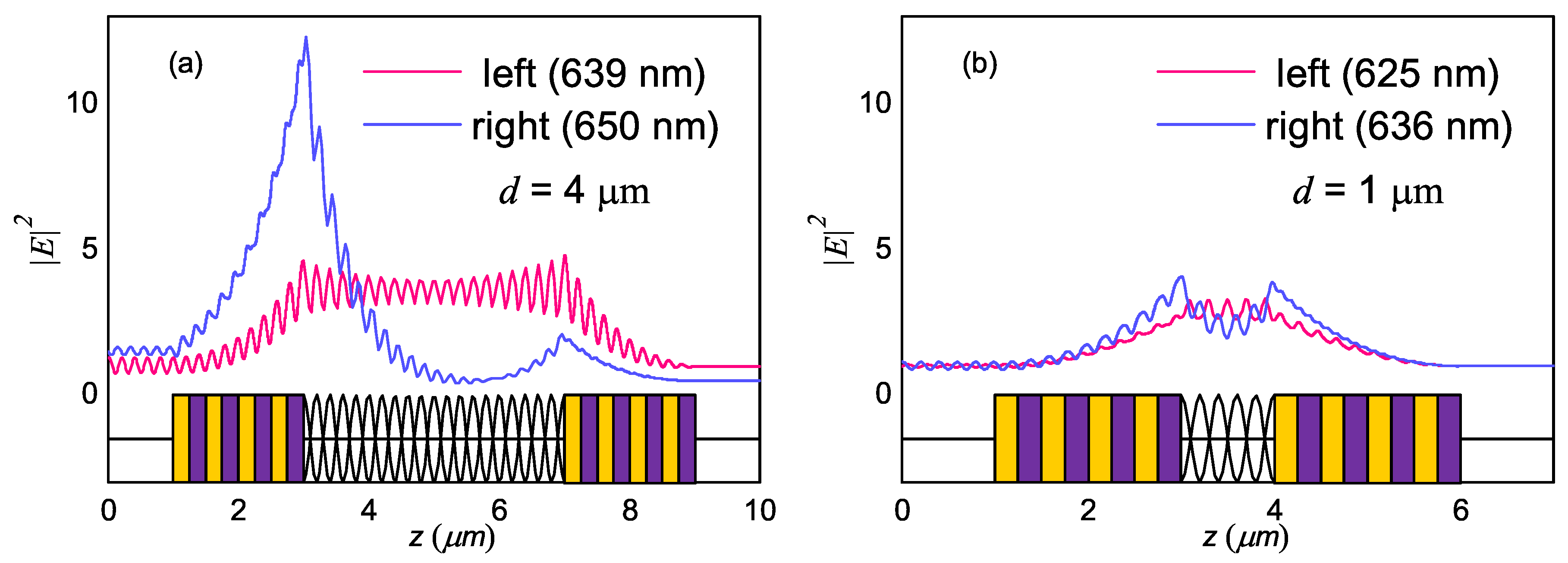
Figure 2 shows the transmittance spectra for the circular polarizations of incidence light as a function of the CLC width, which were simulated using the 4 × 4 Berreman matrix [29]. One can see the behavior of the spectrum at the right-handed circular polarization of the incident light. At the large CLC thicknesses, the transmittance peak corresponding to the OTS was observed for this polarization. This fact was confirmed by the spatial distribution of the squared absolute value of electric field | E | 2 ( z ) at a wavelength of 650 nm (the blue line in Figure 3a). The field was localized with the maxima at the CLC boundary. Since the light fell from the left and the CLC had a high reflectivity, the field was localized stronger on the left CLC boundary. As the distance to the boundary increased, the fields exponentially decayed. The presence of a wave exciting the mode gave an insignificant deviation from the exponential law. However, the applied Berreman method did not allow us to exclude the exciting wave and to construct a pure mode as in [30] and for hybrid modes in CLC [31].
A decrease in the CLC layer thickness led to the overlap of the OTS electromagnetic fields (Figure 3b), which eliminated the degeneracy. The frequency split, and two transmittance peaks arose in the spectrum, which corresponded to symmetric and antisymmetric modes (Figure 4), similar to the modes studied in [16,32].
The specific feature of the CLC was the dependence of the spectrum on the polarization of the incident light. The nondiffracting polarization opposite to the CLC twisting direction was not reflected from the cholesteric. Since the investigated system contained a right-handed CLC, the OTS did not occur for the left-handed circular polarization. At this polarization, the structure under study became similar to the Fabry–Pérot cavity, and resonances arose in its transmittance spectrum. The number of these resonances depended on the distance between the mirrors (Figure 2b). The | E | 2 ( z ) dependence for such a circular polarization of the incident light (the red line in Figure 3) confirmed that the peaks for the left-handed circular polarization corresponded to the cavity modes. Thus, the transmittance spectra for the circular polarizations of the incident light were different. At the non-circular polarizations of the incident light, the peaks arose at all frequencies.
To ascertain the validity of the obtained results in addition to the numerical simulation, we developed the analytical description of the system. For the scalar systems, the equation for a single OTS localized at the interface between two media has the following form for the arbitrary wave polarization [4]:
r L r R e 2 i Φ = 1 .
Here, r L and r R are the amplitude reflectances of the left and right mirrors, respectively, and Φ is the phase variation for the wave transmitted through the layer separating the mirrors. Let us consider the occurrence of a single chiral OTS at the CLC/PPAM interface. We assumed Equation (1) to be valid at the normal incidence for the diffracting circular polarization, if the relation to the nondiffracting polarization is ignored. Therefore, for the chiral OTS, Φ should be replaced by φ .
The amplitude reflectance of the left mirror, which is a CLC, is [33]:
r L = r C L C = i δ sin q d ( ( q τ / κ 2 ) cos q d + i ( ( τ / 2 κ ) 2 + ( q / κ ) 2 1 ) sin q d .
Here, δ = ( n e 2 n 0 2 ) ( n e 2 + n 0 2 ) , κ = ω ( ( n e 2 + n 0 2 ) / 2 ) c , and τ = 4 π p is the CLC reciprocal lattice vector. The vector of the wave diffracting in the CLC is:
q = κ 1 + ( τ / 2 κ ) 2 ( τ / κ ) 2 + δ 2 .
For the right mirror, the reflectance of the layered structure with N periods is determined as [34]:
r R = r P P A M = C U N 1 A U N 1 U N 2 ,
where U N = sin 2 a N 1 K sin 2 a K , K = 1 2 a arccos ( A + D 2 ) is the Bloch wavenumber.
Since we only investigate the case of the normal incidence, elements A, B, C and D of the transfer matrix for one cell, which relate the plane wave amplitudes in the first unit cell layer to the amplitudes in the neighboring unit cell, can be written in the form:
A = e i k 1 z a cos k 2 z a + 1 2 i k 2 z k 1 z + k 1 z k 2 z sin k 2 z a ; B = e i k 1 z a 1 2 i k 2 z k 1 z k 1 z k 2 z sin k 2 z a ; C = e i k 1 z a 1 2 i k 2 z k 1 z k 1 z k 2 z sin k 2 z a ; D = e i k 1 z a cos k 2 z a 1 2 i k 2 z k 1 z + k 1 z k 2 z sin k 2 z a ,
where k 1 z = ( ω / c ) n e 2 , k 2 z = ( ω / c ) n o 2 are the wave vectors for the first and second media, respectively, and 2a is the PPAM period. The resulting equation for the chiral OTS localized at the interface between two media with reflectances r P P A M and r C L C and the angle φ between the optical axes is:
r P P A M r C L C e 2 i φ = 1 .
The solution of this equation at the center of the Bragg reflection of the mirrors leads to the result, in which at the angle φ = π / 4 , the single chiral OTS is excited exactly at the CLC band gap center, which is consistent with the predictions from [23,24]. The equation for the coupled chiral OTSs should contain a term responsible for the coupling value. Obviously, it should be proportional to the CLC thickness and reflectance. We suggested that it can be written in the form ± t C L C r C L C , as was done for scalar structures in [13,32]. The amplitude transmittance of the CLC is determined as [33]:
t C L C = e i τ d / 2 ( ( q τ / κ 2 ) ( ( q τ / κ 2 ) cos q d + i ( ( τ / 2 κ ) 2 + ( q / κ ) 2 1 ) sin q d .
Thus, for the coupled chiral OTSs, we have:
1 ± t C L C r C L C = r P P A M r C L C e 2 i φ .
Near the Bragg frequency, the amplitudes r P P A M and r C L C are almost unity. We denote the phase of expression ± t C L C r C L C by θ ± and the phases of the waves reflected from the PPAM and CLC by φ P P A M and φ C L C and write Equation (8) in the form:
θ ± = φ P P A M + φ C L C + 2 φ .
This equation allowed us to determine the eigenfrequencies of the coupled chiral OTSs. The frequencies calculated in this manner at different CLC thicknesses d (dashed lines in Figure 2a) were consistent with the simulation data (the solid line in Figure 2a).
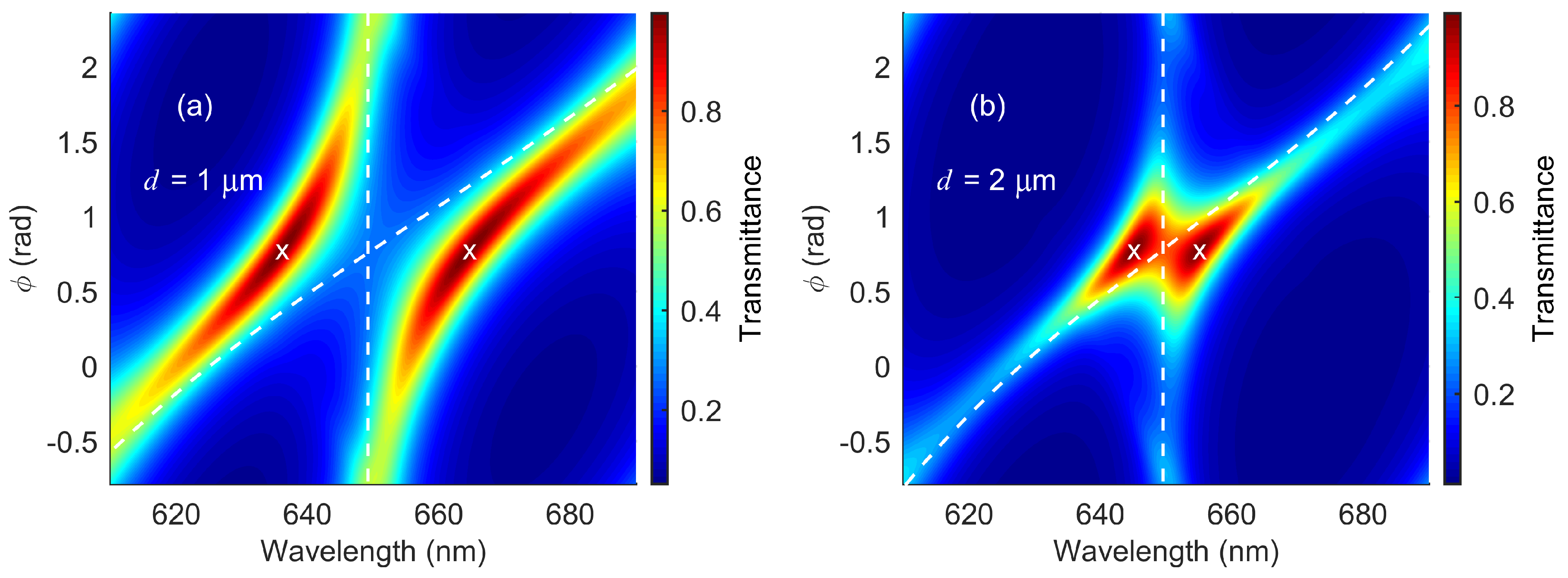
If the CLC layer was thick and the angles ψ and φ were equal to π / 4 , two OTSs were excited in the system, which occurred in the spectrum at the same frequency. Varying one of the angles, one could tune a spectral position of one of the OTSs. We numerically investigated the interaction between the OTSs localized at both CLC boundaries as a function of the angle φ (Figure 5). The peak corresponding to the OTS localized at the left CLC boundary did not change its wavelength. At φ = π / 4 , the two frequencies coincided and the splitting occurred. Upon variation in φ , the spectrum demonstrated anticrossing typical of the bound states. White lines in the figures show the solution of Equation (6) for single OTSs.
The transmittance spectrum at the normal incidence of the left-handed nondiffracting polarization, at which the OTSs are not excited (Figure 2b), can be found using the well-known expression for the transmittance of the Fabry–Pérot cavity [35]:
T F P = ( 1 | r P P A M | 2 ) 2 ( 1 | r P P A M | 2 ) 2 + 4 | r P P A M | 2 sin 2 ( δ / 2 )
In the investigated model, δ / 2 should be written in the form:
δ / 2 = φ P P A M π / 2 ω n d / c
where n is the average refractive index of the CLC. The transmittance spectra for the structure with the left-handed nondiffracting polarization calculated using Equation (10) are shown by dashed lines in Figure 2b.
An important advantage of the CLC as a photonic material is its high sensitivity to external fields. The electromagnetic field and temperature [36] can change the CLC helix pitch or even transform it to another aggregate state. As the helix pitch changes, the peaks shift, and the CLC and PPAM band gaps no longer overlap. Thus, the OTSs will not be excited for the diffracting polarization, and the system will turn to the Fabry–Pérot cavity filled with anisotropic helical structures [37,38]. The spectra for both circular polarizations will become identical, and doublets will arise in them. After the phase transition of the CLC to the isotropic state, the system transforms to a conventional Fabry–Pérot cavity.

4. Conclusions

We demonstrated the existence of the modes caused by coupling of two chiral optical Tamm states localized at the interface between the CLC and anisotropic mirrors. The mirrors represent uniaxial layered structures, in which each layer is rotated by 90 relative to the previous one. Such a structure is polarization-preserving. The need for these mirrors is caused by the polarization properties of the CLC. The investigated modes are only excited at the diffracting polarization of the incident light. As the CLC layer thickness decreases, the OTS frequency spectral split is predicted. The split value depends on the layer thickness. We found analytically and numerically the frequencies of the spectral manifestation of the chiral OTSs. Varying the angle between the CLC and PPAM optical axes, one can control the OTS coupling value, thereby tuning the transmittance spectrum of the structure. At the opposite circular polarization, which does not reflect from the CLC, the OTSs are not excited, and the system becomes analogous to a Fabry–Perot cavity filled with an anisotropic helical structure. The possible tuning of the spectra by external factors was discussed.

Author Contributions

M.V.P. performed the calculations, visualized the results and drafted the manuscript. I.V.T. and N.V.R. helped with the software and methods and checked the analytical expressions. S.Ya.V. supervised the whole study and finalized the manuscript

Funding

This research was funded by the Russian Foundation for Basic Research, Government of Krasnoyarsk Territory, Krasnoyarsk Region Science and Technology Support Fund, to the research Project Nos. 17-42-240464 and 18-42-243025.

Conflicts of Interest

The authors declare no conflict of interest.

References

  1. Goto, T.; Dorofeenko, A.V.; Merzlikin, A.M.; Baryshev, A.V.; Vinogradov, A.P.; Inoue, M.; Lisyansky, A.A.; Granovsky, A.B. Optical Tamm states in one-dimensional magnetophotonic structures. Phys. Rev. Lett. 2008, 101, 113902. [Google Scholar] [CrossRef] [PubMed]
  2. Kavokin, A.V.; Shelykh, I.A.; Malpuech, G. Lossless interface modes at the boundary between two periodic dielectric structures. Phys. Rev. B 2005, 72, 233102. [Google Scholar] [CrossRef] [Green Version]
  3. Vinogradov, A.P.; Dorofeenko, A.V.; Merzlikin, A.M.; Lisyansky, A.A. Surface states in photonic crystals. Phys. Uspekhi 2010, 53, 243–256. [Google Scholar] [CrossRef]
  4. Kaliteevski, M.A.; Iorsh, I.; Brand, S.; Abram, R.A.; Chamberlain, J.M.; Kavokin, A.V.; Shelykh, I.A. Tamm plasmon-polaritons: Possible electromagnetic states at the interface of a metal and a dielectric Bragg mirror. Phys. Rev. B 2007, 76, 165415. [Google Scholar] [CrossRef] [Green Version]
  5. Symonds, C.; Lheureux, G.; Hugonin, J.-P.; Greffet, J.-J.; Laverdant, J.; Brucoli, G.; Lemaitre, A.; Senellart, P.; Bellessa, J. Confined Tamm plasmon lasers. Nano Lett. 2013, 13, 3179–3184. [Google Scholar] [CrossRef] [PubMed]
  6. Jiménez-Solano, A.; Galisteo-López, J.F.; Míguez, H. Flexible and adaptable light-emitting coatings for arbitrary metal surfaces based on optical tamm mode coupling. Adv. Opt. Mater. 2017, 6, 1700560. [Google Scholar] [CrossRef]
  7. Yang, Z.-Y.; Ishii, S.; Yokoyama, T.; Dao, T.D.; Sun, M.-G.; Pankin, P.S.; Timofeev, I.V.; Nagao, T.; Chen, K.-P. Narrowband wavelength selective thermal emitters by confined tamm plasmon polaritons. ACS Photonics 2017, 4, 2212–2219. [Google Scholar] [CrossRef]
  8. Zhang, X.-L.; Feng, J.; Han, X.-C.; Liu, Y.-F.; Chen, Q.-D.; Song, J.-F.; Sun, H.-B. Hybrid Tamm plasmon-polariton/microcavity modes for white top-emitting organic light-emitting devices. Optica 2015, 2, 579–584. [Google Scholar] [CrossRef]
  9. Huang, S.-G.; Chen, K.-P.; Jeng, S.-C. Phase sensitive sensor on Tamm plasmon devicess. Opt. Mater. Express 2017, 72, 1267–1273. [Google Scholar] [CrossRef]
  10. Kumar, S.; Maji, P.S.; Das, R. Tamm-plasmon resonance based temperature sensor in a Ta2O5/SiO2 based distributed Bragg reflector. Sens. Actuators A Phys. 2017, 260, 10–15. [Google Scholar] [CrossRef]
  11. Zhang, X.-L.; Song, J.-F.; Li, X.-B.; Feng, J.; Sun, H.-B. Optical Tamm states enhanced broad-band absorption of organic solar cells. Appl. Phys. Lett. 2012, 101, 243901. [Google Scholar] [CrossRef]
  12. Cheng, H.-C.; Kuo, C.-Y.; Hung, Y.-J.; Chen, K.-P.; Jeng, S.-C. Liquid-crystal active tamm-plasmon devices. Phys. Rev. Appl. 2018, 9, 064034. [Google Scholar] [CrossRef]
  13. Kaliteevski, M.; Brand, S.; Abram, R.A.; Iorsh, I.; Kavokin, A.V.; Shelykh, I.A. Hybrid states of Tamm plasmons and exciton polaritons. Appl. Phys. Lett. 2009, 95, 251108. [Google Scholar] [CrossRef] [Green Version]
  14. Rahman, S.K.S.-U.; Klein, T.; Klembt, S.; Gutowski, J.; Hommel, D.; Sebald, K. Observation of a hybrid state of Tamm plasmons and microcavity exciton polaritons. Sci. Rep. 2016, 6, 34392. [Google Scholar] [CrossRef] [PubMed] [Green Version]
  15. Afinogenov, B.I.; Bessonov, V.O.; Nikulin, A.A.; Fedyanin, A.A. Observation of hybrid state of Tamm and surface plasmon-polaritons in one-dimensional photonic crystals. Appl. Phys. Lett. 2013, 103, 061112. [Google Scholar] [CrossRef]
  16. Vetrov, S.Ya.; Bikbaev, R.G.; Timofeev, I.V. Optical Tamm states at the interface between a photonic crystal and a nanocomposite with resonance dispersion. J. Exp. Theor. Phys. 2013, 117, 988–998. [Google Scholar] [CrossRef]
  17. Pankin, P.S.; Vetrov, S.Ya.; Timofeev, I.V. Tunable hybrid Tamm-microcavity states. J. Opt. Soc. Am. B: Opt. Phys. 2017, 34, 2633–2639. [Google Scholar] [CrossRef]
  18. Blinov, L.M. Structure and Properties of Liquid Crystals; Springer: Berlin, Germany, 2011; ISBN 978-90-481-8829-1. [Google Scholar]
  19. Vetrov, S.Y.; Pyatnov, M.V.; Timofeev, I.V. Surface modes in “photonic cholesteric liquid crystal—Phase plate—Metal” structure. Opt. Lett. 2014, 39, 2743–2746. [Google Scholar] [CrossRef] [PubMed]
  20. Vetrov, S.Ya.; Pyatnov, M.V.; Timofeev, I.V. Spectral and polarization properties of a ‘cholesteric liquid crystal—Phase plate—Metal’structure. J. Opt. 2015, 18, 015103. [Google Scholar] [CrossRef]
  21. Pyatnov, M.V.; Vetrov, S.Ya.; Timofeev, I.V. Localised optical states in a structure formed by two oppositely handed cholesteric liquid crystal layers and a metal. Liq. Cryst. 2017, 44, 674–678. [Google Scholar] [CrossRef]
  22. Pyatnov, M.V.; Vetrov, S.Ya.; Timofeev, I.V. Localized optical modes in a defect-containing liquid-crystal structure adjacent to the metal. J. Opt. Soc. Am. B: Opt. Phys. 2017, 34, 2011–2017. [Google Scholar] [CrossRef]
  23. Timofeev, I.V.; Vetrov, S.Ya. Chiral optical Tamm states at the boundary of the medium with helical symmetry of the dielectric tensor. JETP Lett. 2016, 104, 380–383. [Google Scholar] [CrossRef] [Green Version]
  24. Timofeev, I.V.; Pankin, P.S.; Vetrov, S.Ya.; Arkhipkin, V.G.; Lee, W.; Zyryanov, V.Ya. Chiral optical Tamm states: Temporal coupled-mode theory. Crystals 2017, 7, 113. [Google Scholar] [CrossRef]
  25. Ding, F.; Wang, Z.; He, S.; Shalaev, V.M.; Kildishev, A.V. Broadband high-efficiency half-wave plate: A supercell-based plasmonic metasurface approach. ACS Nano 2015, 9, 4111–4119. [Google Scholar] [CrossRef] [PubMed]
  26. Matsuhisa, Y.; Ozaki, R.; Yoshino, K.; Ozaki, M. High Q defect mode and laser action in one-dimensional hybrid photonic crystal containing cholesteric liquid crystal. Appl. Phys. Lett. 2006, 89, 101109. [Google Scholar] [CrossRef]
  27. Rudakova, N.V.; Timofeev, I.V.; Pankin, P.S.; Vetrov, S.Y. Polarization-preserving anisotropic mirror on the basis of metal–dielectric nanocomposite. Bull. Russ. Acad. Sci. Phys. 2017, 81, 5–9. [Google Scholar] [CrossRef] [Green Version]
  28. Rudakova, N.V.; Timofeev, I.V.; Bikbaev, R.G.; Pyatnov, M.V.; Vetrov, S.Ya.; Lee, W. Chiral Optical Tamm states at the interface between a cholesteric and an all-dielectric polarization-preserving anisotropic mirror. arXiv 2018, arXiv:1808.06243. [Google Scholar]
  29. Berreman, D.W. Optics in stratified and anisotropic media: 4 × 4-matrix formulation. J. Opt. Soc. Am. 1972, 62, 502–510. [Google Scholar] [CrossRef]
  30. Belyakov, V.A.; Semenov, S.V. Optical defect modes in chiral liquid crystals. J. Exp. Teor. Phys. 2011, 112, 694–710. [Google Scholar] [CrossRef]
  31. Avendano, C.G.; Ponti, S.; Reyes, J.A.; Oldano, C. Multiplet structure of the defect modes in 1D helical photonic crystals with twist defects. J. Phys. A Math. Gen. 2005, 38, 8821–8840. [Google Scholar] [CrossRef]
  32. Iorsh, I.; Panicheva, P.V.; Slovinskii, I.A.; Kaliteevski, M.A. Coupled Tamm plasmons. Tech. Phys. Lett. 2012, 38, 351–353. [Google Scholar] [CrossRef]
  33. Belyakov, V.A. Diffraction Optics of Complex-Structured Periodic Media; Springer: Berlin, Germany, 1992; ISBN 978-1-4612-4396-0. [Google Scholar]
  34. Yariv, A.; Yeh, P. Optical Waves in Crystals; John Wiley & Sons: New York, NY, USA, 1984; ISBN-13: 978-0471430810, ISBN-10: 0471430811. [Google Scholar]
  35. Haus, H.A. Waves and Fields in Optoelectronics; Prentice-Hall: Upper Saddle River, NJ, USA, 1984; ISBN-13: 9780139460531, ISBN-10: 0139460535. [Google Scholar]
  36. Dolganov, P.V.; Gordeev, S.O.; Dolganov, V.K.; Bobrovsky, A.Y. Photo- and thermo-induced variation of photonic properties of cholesteric liquid crystal containing azobenzene-based chiral dopant. Mol. Cryst. Liq. Cryst. 2016, 633, 14–22. [Google Scholar] [CrossRef]
  37. Zhuang, Z.; Patel, J.S. Behavior of cholesteric liquid crystals in a Fabry-Perot cavity. Opt. Lett. 1999, 24, 1759–1761. [Google Scholar] [CrossRef] [PubMed]
  38. Abdulhalim, I. Unique optical properties of anisotropic helical structures in a Fabry-Perot cavity. Opt. Lett. 1999, 31, 3019–3021. [Google Scholar] [CrossRef]
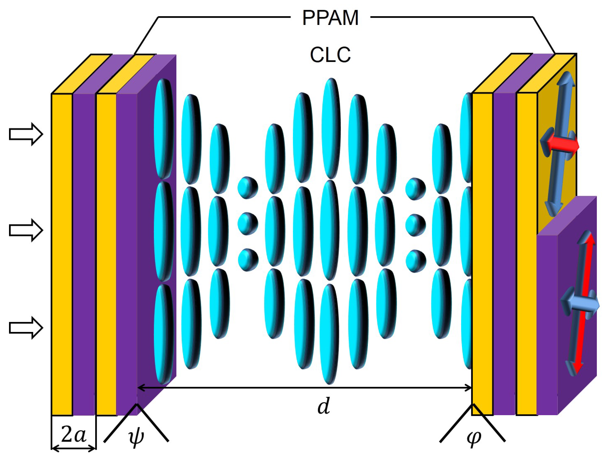
Figure 1. Schematic of the structure. Color arrows show the direction of optical axes of the polarization-preserving anisotropic mirror (PPAM) layers. Each PPAM consists of 10 periods. CLC, cholesteric liquid crystal.
Photonics 05 00030 g001
Figure 2. Dependence of the transmittance spectrum for (a) the right- and (b) left-handed circular polarizations of the incident light on CLC layer thickness d. Dashed lines in Figure 2a show the optical Tamm state (OTS) spectral positions calculated using Formula (9) and dashed lines in Figure 2b the transmittance spectra for the nondiffracting polarization analytically calculated using Formula (11); φ = π / 4 .
Photonics 05 00030 g002
Figure 3. Spatial distribution of the local electric field intensity in the structure for the circular polarizations of incidence light. (a) d = 4 μ m and (b) d = 1 μ m. Each PPAM consists of 10 periods; φ = π / 4 .
Photonics 05 00030 g003
Figure 4. Spatial distribution of the local electric field in the structure for the right circular polarizations of incidence light. Each PPAM consists of 10 periods; d = 1 μ m, φ = π / 4 .
Photonics 05 00030 g004
Figure 5. Transmittance of the structure from Figure 1 as a function of angle φ at different CLC widths d. (a) d = 1 μ m and (b) d = 2 μ m. White lines show the positions of single OTSs calculated using Equation (6). The crosses correspond to OTS wavelengths for φ = π / 4 .
Photonics 05 00030 g005