1. Introduction
The breach of time-reversal symmetry and reciprocity in engineered photonic structures has garnered an immense attention in the community, partly due to optical information processing and communications based on integrated photonic devices demanding on-chip nonreciprocal light transport. It is known that time-reversal symmetry is a useful notion in non-dissipative systems, while reciprocity is more general in the sense of the invariance of photon transmission amplitudes under exchange of source and detector [
1]. On a fundamental level, optical nonreciprocity is very challenging, even in theory [
2], as breaking the time-reversal symmetry in light-matter interactions allows the production of new photonic states, such as quantum Hall states and topological states. On the practical level, nonreciprocal devices are not only crucial for a number of signal processing applications but also desirable for simplifying the construction of photonic networks.
To break reciprocity, the conventional solution is to guide light through a material exhibiting strong magneto-optical effects (Faraday rotation) [
2,
3,
4]. This method has been generally adopted in commercial optical isolators and circulators. However, unfortunately these bulky components are difficult to be implemented with the existing complementary metal-oxide-semiconductor (CMOS) processing, and the use of external magnetic fields is also deleterious to the functionalities of nearby devices [
5,
6]. The quest for on-chip optical nonreciprocal devices has recently spawned a number of strategies beyond the Faraday effect. Among them include optical nonlinearity [
7,
8,
9,
10,
11,
12,
13,
14], optical-thermo effect [
15], interband photonic transitions [
16,
17], parity-time symmetric optics [
18,
19,
20], and interfering parametric processes [
21,
22]. Despite these isolation mechanisms could be in principle used for optical circulation, yet, to date functional circulators are mainly implemented with the common Faraday rotation. To be compatible with the current CMOS technology, recent efforts have been made on the reduction of the size of these circulators by resonantly enhancing the interaction between light fields and magneto-optically active media. This leads to the concepts for on-chip circulators using photonic crystal [
23] or microring resonators [
24,
25,
26]. Thus far, there are limited experimental realizations for magneto-optical microring resonators [
5] but none for photonic-crystal microresonators. It is, thus, intriguing to know whether a simpler scheme, relying only on existing components that are readily fabricated in the CMOS, can be developed to attain both optical isolation and circulation in a silicon photonic platform.
In contrast to previous proposals, in our recent experiment [
27] we employ a novel, yet much simpler, architecture using only one active whispering-gallery-mode (WGM) microtoroid cavity [
28] to realize on-chip optical asymmetric transmission which could be potentially useful for isolation and circulation. The scheme explores gain-saturation nonlinearity, and shows incredible asymmetric light transmission performance within telecom bands. Not only compatible with the current CMOS technique, our compact device works for a very broad range of input power levels, and exhibits remarkable isolation performance with substantial reductions of technological complexity and achievable footprint. These features make our system serve as a promising fundamental building block for future integrated photonic networks.
Here, we would like to provide detailed analysis on this work and investigate the observed asymmetric light transmission from the theoretical point of view. Although our developed theory is simply the standard coupled-mode theory, it agrees with the experiment and gives an intuitive picture of the nonreciprocity observed in this system. Additionally, we further briefly discuss no violation of the second law of thermodynamics. In addition to being nonreciprocal, we expect this system to have significant impacts on both fundamental physics and device applications.
2. Gain-Saturation Induced On-Chip Optical Nonreciprocity
Figures of Merit of On-Chip Optical Nonreciprocal Devices. Before discussing our recent work on the realization of on-chip light asymmetric transmission [
27], it would be instructive to give a brief summary of figures of merits for evaluating nonreciprocal functionalities of chip-size devices. To be a good on-chip nonreciprocal device, it usually should more or less possess the following properties:
- (1)
Be compatible with current CMOS process;
- (2)
Exhibiting sufficiently high isolation ratios;
- (3)
Showing sufficiently low insertion losses;
- (4)
Allowing a broad range of input light power levels;
- (5)
Working for a broad range of wavelengths; ……
Abiding by this analysis, our scheme well satisfies the properties (1−4) and displays superior asymmetric light transport under a controllable and engineering way. Similar to all resonance-enhanced optical devices, although our system is bandwidth-limited, its operation wavelengths can be thermally tuned or be inhomogeneously broadened by anisotropic doping of rare-earth ions, and should work across a large wavelength band.
Our nonreciprocal device explores the strong gain-saturation nonlinearity existing in a high-quality (
Q) active WGM microtoroid resonator, fabricated from an erbium-doped silica sol-gel film [
28]. As sketched in
Figure 1, our scheme consists of a microtoroid coupled with two tapered fibers (labeled as fibers 1 and 2). The active microcavity produces an effective gain (
) at the 1550 nm band by optical pumping with a 1480 nm narrow-linewidth tunable laser. To catch the essential physics behind but without introducing further complication into the problem, a simple model based on the coupled-mode theory [
20,
29] is developed to describe the signal dynamics and solved under the steady-state condition by neglecting the backscattering-induced mode splitting [
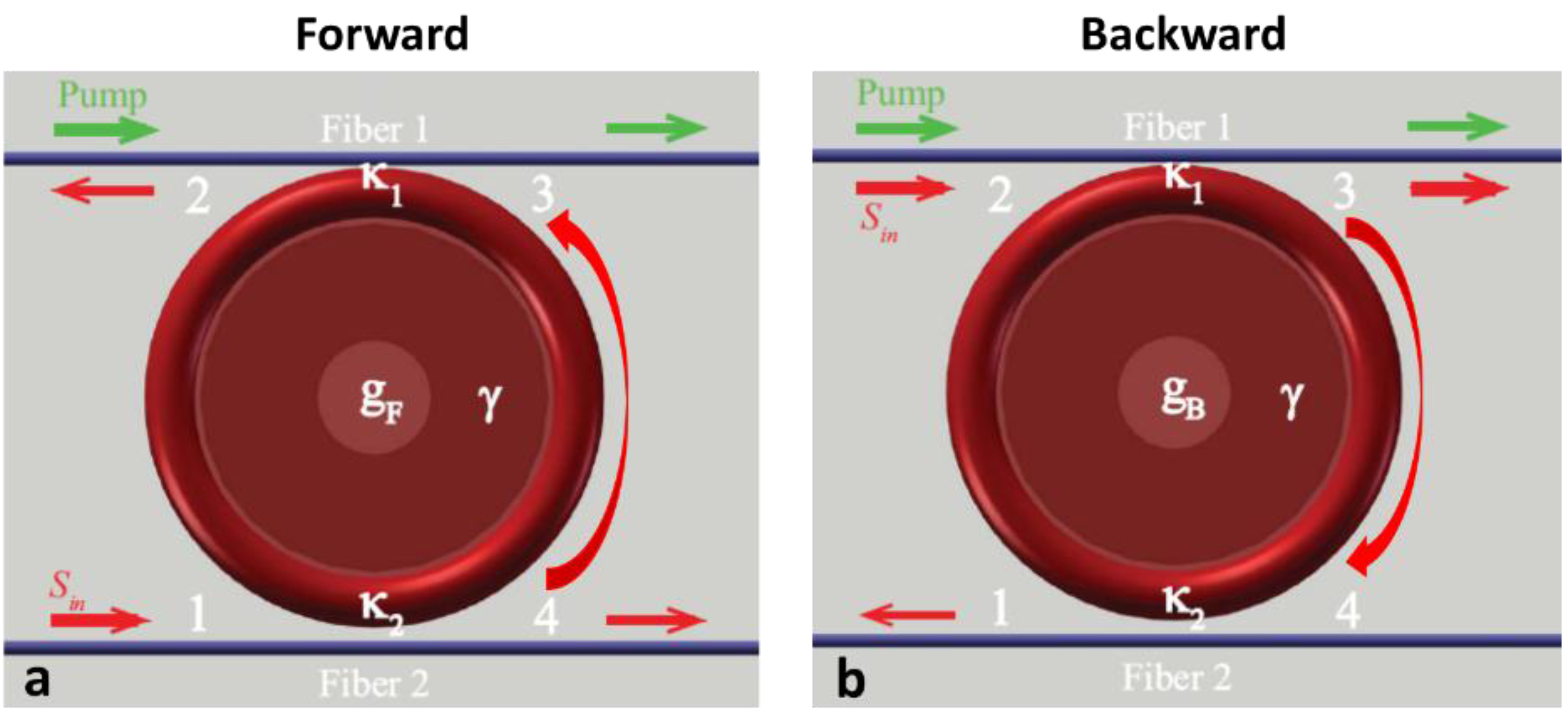
30]. For the forward (backward) light propagation configuration (
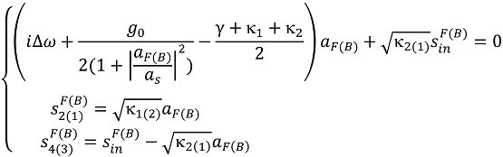
Figure 1), the signal transmittances at ports 2 (1) and 4 (3) are, respectively, described by:
Here, denotes the signal-field amplitude inside the cavity for the forward (backward) light transport configuration; is the cavity intrinsic decay rate; κ1,2 represent the coupling strength between the toroid and fiber 1 (2); is the cavity frequency detuning; represents the gain as ; stands for the gain-saturation threshold; and is the amplitude of the forward (backward) input signal field. The forward (backward) effective gain takes the form of with , where is the real gain provided by the doped erbium ions. The coupled Equation (1) is the basic starting point for us to theoretically analyze the signal nonreciprocal transport in such a system.
Figure 1.
An active WGM microtoroid resonator coupled to two tapered optical fibers for the experimental realizations of on-chip asymmetric light transmission. The signal laser is tuned to be resonant with the cavity resonant frequency (). The pump field is used to produce an effective gain () in the forward propagation and in the backward) for the signal wave through optically pumping doped erbium-doped ions. κ1 and κ2 represent the coupling strengths of toroid-fiber 1 and toroid-fiber 2, respectively. is the cavity intrinsic decay rate. Light transports are examined by measuring transmittance spectra in the forward (a) and backward (b) propagation configurations. stands for the amplitude of the input signal field.
Gain-Saturation Induced Optical Isolation. Optical isolation would be possible for blocking light in one direction but allowing light to pass in the opposite direction. This is important, say, if one wants to protect a laser from back reflections, as they may disturb the laser operation or cause undesired multipath interference in an optical communication system. Moreover, the use of an isolator can suppress spurious interactions between different devices and unwanted light routing. Thus, isolation imposes a specific requirement on the elements of the scattering matrix that connects its two ports. As emphasized by Jalas and his colleagues [2], there needs to be a pair of modes, one belonging to each port, such that the transmission from mode m in port 1 to mode n in port 2 is essentially nonzero, whereas the transmission from mode n in port 2 to mode m in port 1 is close to zero. It is yet unimportant in the latter case where the energy goes—it can be dissipated into the device, transmitted to a third port or emitted away. The corresponding asymmertic scatterting matrix for such a two-port isolator takes the form of , which indicates the breach of the Lorentz reciprocity and allows only one-way transmission.
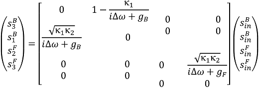
In the light of this definition, we can recast Equation (1) into the following matrix form
It becomes now apparent from Equation (2) that the realization of
would enable breaking the symmetry between forward and backward signal transmissions. To meet this condition, it requires strong asymmetric coupling (
) to smash the optical reciprocity as readily observed from the definition of
. In the presence of the gain saturation effect, such asymmetric couplings will result in different
and
even with the same input signal powers (
). Consequently, this leads to the forward gain
be different from the backward gain
. Theoretically, by tuning the coupling strengths the scheme admits highly directional transmission in a controllable and switchable manner, depending on how much
can be largely made different from
. For optical isolation, a very useful concept—Isolation ratio (IR)—has been extensively adopted in the society as a figure of merit for quantitatively characterizing their asymmetric transmission performance, and it is defined as
where the normalized signal output transmittances at ports 2 and 1 for forward and backward propagation configurations are given by
The physics becomes clear from Equation (3): a positive IR means more forward output transmission than backward output, while a negative IR implies the opposite outcome. As being a simpler architecture (beyond the Faraday rotation), the current scheme contains several adjustable degrees of freedom—
,
,
, input signal power, dropped pump power,
etc.—for systematic manipulations. Although these degrees of freedom offer us a broad range of the parameter space to tune the achievable IRs, such flexibilities bring up certain difficulty and complexity in the real experimental implementations. To reduce the experimental complexity, in our recent demonstrations we chose one degree of freedom as a variable by making all the others constant. This strategy allows us to carefully study the isolation performance as a function of either
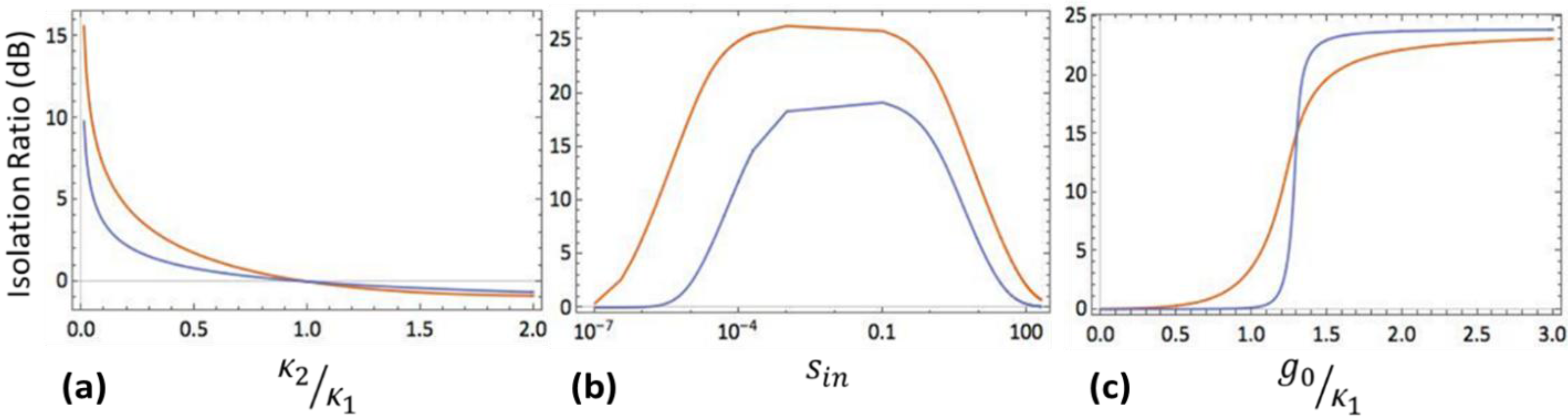
, the input signal power, or the dropped pump power. Albeit the one-cavity configuration makes the scheme simple and elegant, the involved gain-saturation nonlinearity in fact brings rich physics into this system. As shown in
Figure 2, without taking into account back-scattering due to the surface roughness of the microcavity, our simple theory still can correctly predicts the trends of isolation performance in corresponding to the experiment reported in [
27], and also sketch a more complete picture for evaluating this nonreciprocal device. From these figures, one can easily identify the optimal operating range. Of course, the inclusion of back-scattering would provide more accurate description on the dynamics of the system in a quantitative way as illustrated in [
27], and we will not reproduce those results here.
Figure 2.
Superior asymmetric light transmission performance of the system as a function of (a) the coupling strength κ2 (with (, ) for the orange line and (, ) for the blue line); (b) the input signal power (with (, ) for the orange line and (, ) for the blue line); and (c) the dropped pump power (with (, ) for the orange line and (, ) for the blue line). Other parameter: .
Gain-Saturation Induced Optical Bidirectional Transmission. Optical circulators are nonreciprocal optics, which are used to separate light signals that travel in opposite directions in an optical system, analogous to the operations of electronic circulators. In our recent experiment, we choose ports 1, 2, and 3 (
Figure 1) to form a three-port pseudo-circulator, whose power flow direction is determined by the coupling strengths. Port 4 is not relevant in the demonstration. For simplicity, we focus mainly on the circulation scenario considered in the work [
27]. That is, if the signal enters port 1, it is emitted from port 2; but if part of the emitted light is reflected back to the system or the signal is launched from port 2, it drops out from port 3 instead of port 1. In our proof-of-principle experiment [
27], the first step requires the realization of the asymmetric transmission with a high isolation ratio. Then, by adjusting the coupling strengths the system is gradually transformed to operate in the optical pseudo-circulation mode for certain parameter values with a low insertion loss and high directivity. We notice that the performance of a real circulator is mostly characterized by evaluating IRs among different port combinations. Interestingly, in the reported circulation work we introduced another helpful concept—directivity—as another figure of merit to measure the signal power flow in the direction of its strongest emission versus the opposite direction.
In terms of the scattering matrix, we reformulate Equation (1) at the following format:
To describe the power flow direction as the signal is injected from ports 1 or 2, the corresponding forward or backward directivities are, respectively, defined as:
By combining Equations (5) and (6), one can immediately deduce that, as no backscattering [
30] exists in the ideal case, the forward directivity is always infinite. In practice, because of the surface roughness, the Mie scattering causes part of the reflected signal field to exit from port 3 as shown in the experiment. As the signal is incident from port 2, thanks to the gain amplification, the signal output from port 3 is actually larger than its original input power. Recall that in the proposed chip-based optical circulators with ring resonators [
24,
25,
26] and photonic-crystal [
23] resonators, both approaches still employ the magneto-optically induced frequency splitting between the clockwise and counter-clockwise travelling modes. In contrast to those methods, our work exploit the gain-saturation nonlinearity in an active WGM microtoroid through asymmetrical coupling between the cavity and two tapered photonic optical fibers. Although the optical circulator is also one type of one-way light transport device, apparently it has more constraints than an optical isolator. Here, we want to make few remarks on the concept of directivity. We notice that in electromagnetics [
31], as a figure of merit for an antenna directivity has been broadly applied to measure the power density the antenna radiates in the direction of its strongest emission versus the power density radiated by an ideal isotropic radiator emitting the same total power. In the field of microwave circuits [
32], the concept of directivity has been used to characterize the bidirectional amplification of distributed amplifiers. Acoustics [
31] also widely adopts the term directivity as a measure of the radiation pattern from a source to quantify how much of the total energy from the source is radiating in a particular direction. In addition, we become aware that in optical fiber networks [
33], directivity is commonly introduced to describe the transmission in an optical coupler between ports. The qualitative interpretations on the experimental results reported in [
27] go as follows. For the case of the forward/backward directivities studied as a function of the separation distance between the microtoroid and tapered fiber 2 (
i.e., changing
), by gradually decreasing
the output forward signal power at port 2 drops nearly exponentially while the output backward signal at port 3 starts growing nearly exponentially. For the case as a function the dropped pump power, however, the increase of the power is equivalent to linearly increase the bare gain factor
before the saturation occurs. This results in the growth of both forward and backward directivities at first and then reaches steady-state values eventually.
