Research on the Detection of Middle Atmosphere Temperature by Pure Rotating Raman–Rayleigh Scattering LiDAR at Daytime and Nighttime

 , , ,
, , ,
Abstract
1. Introduction
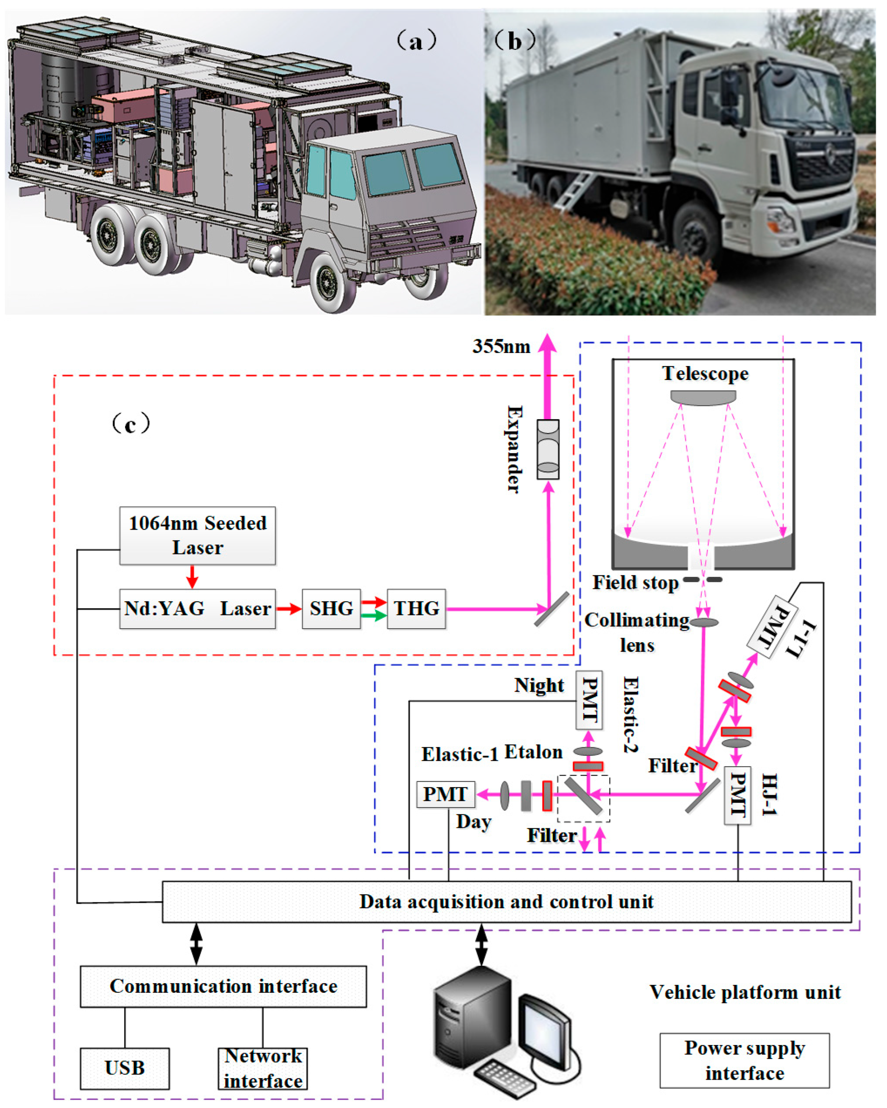
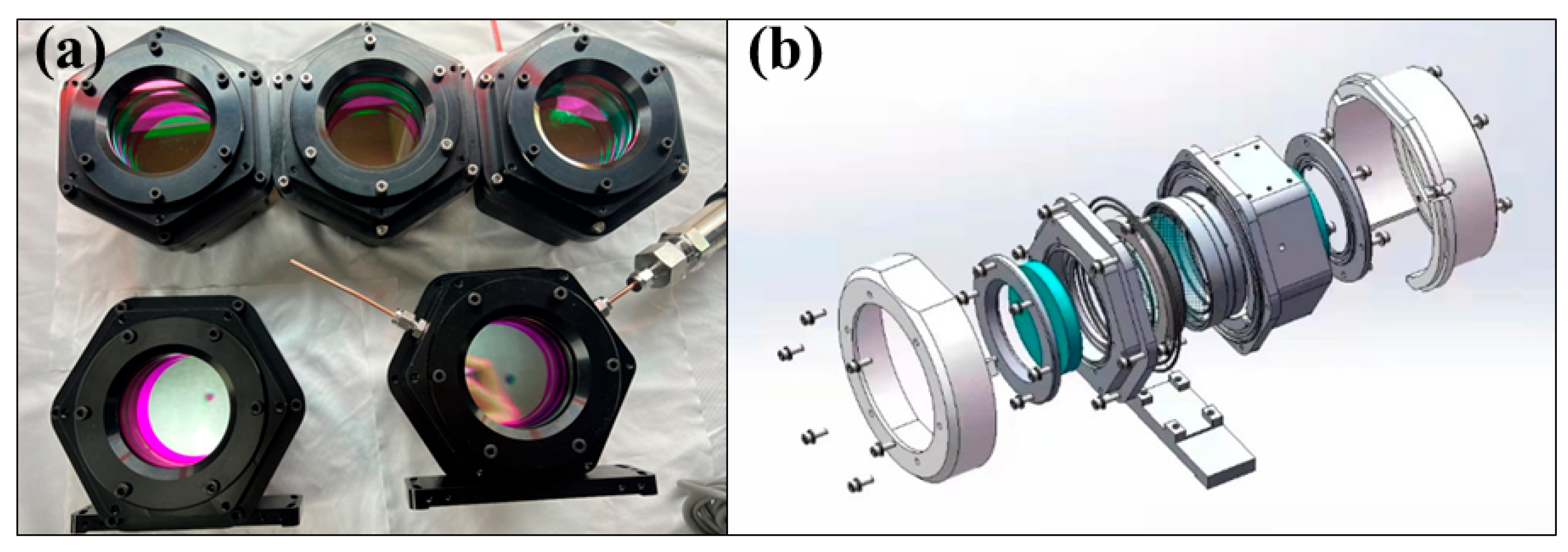
2. Instrument
3. Methodology
4. Results and Analysis
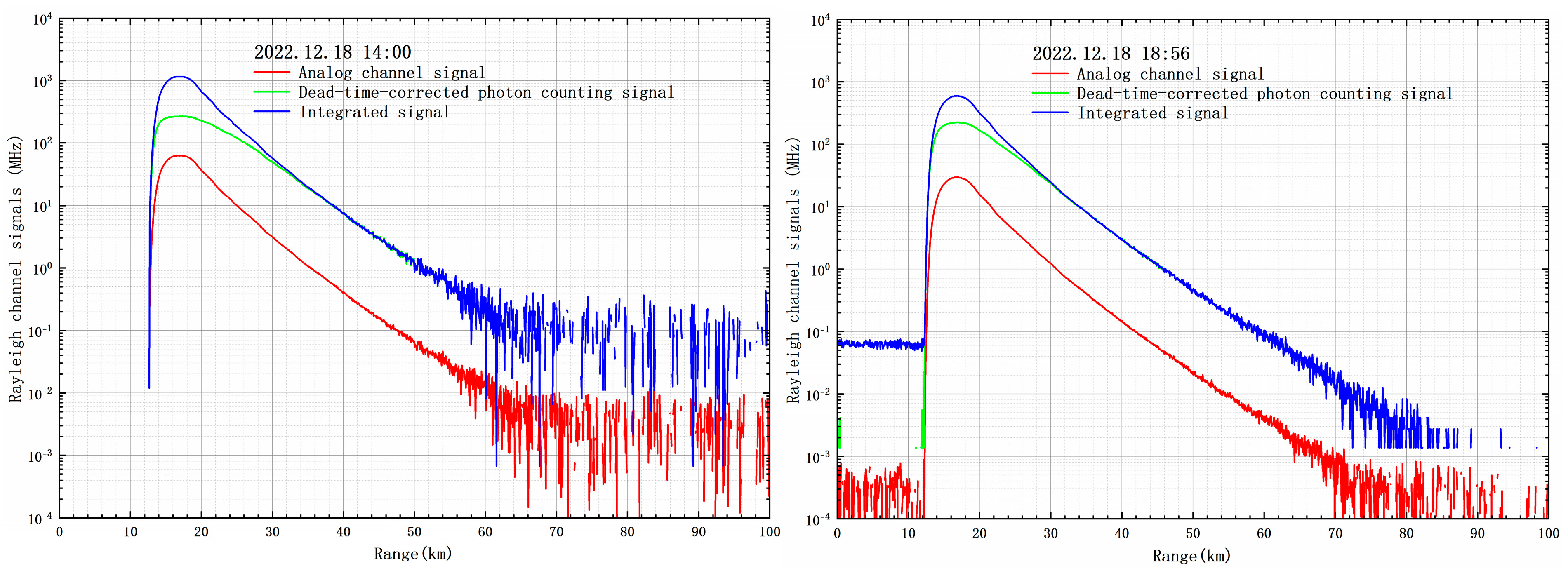
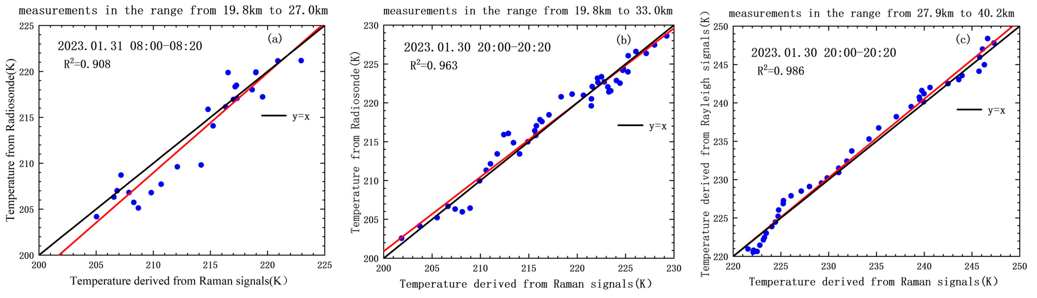
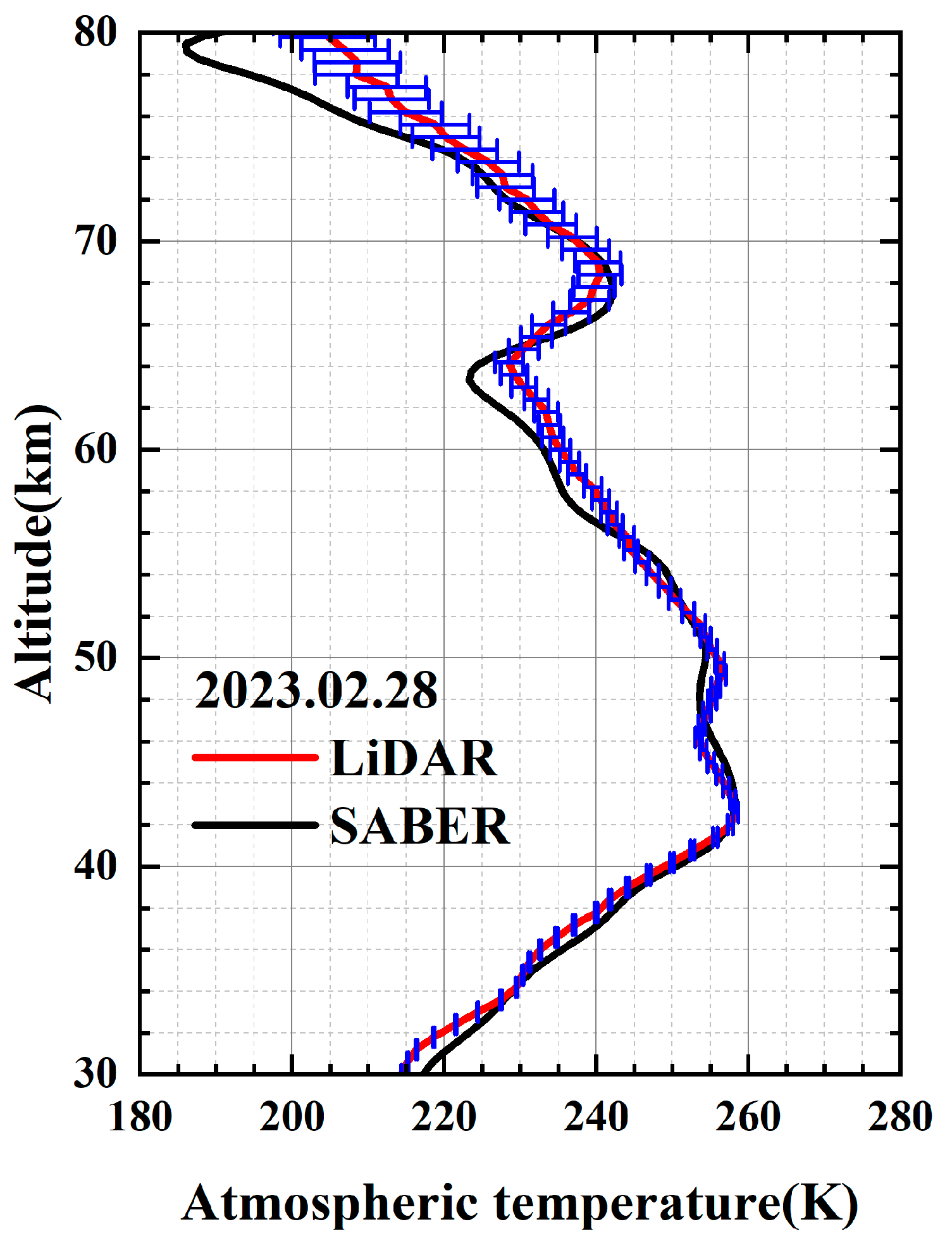
4.1. Comparative Detection and Error Analysis
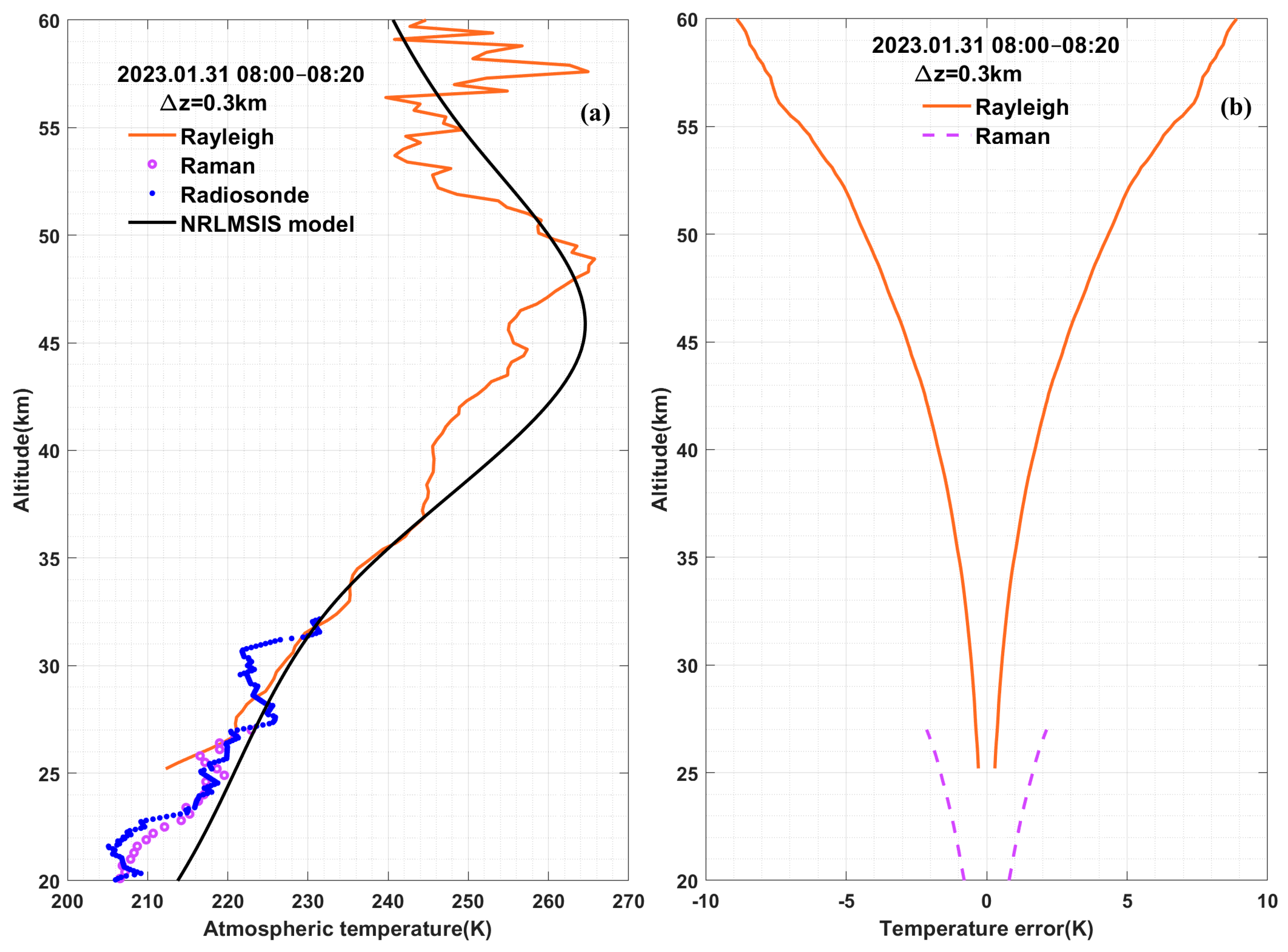
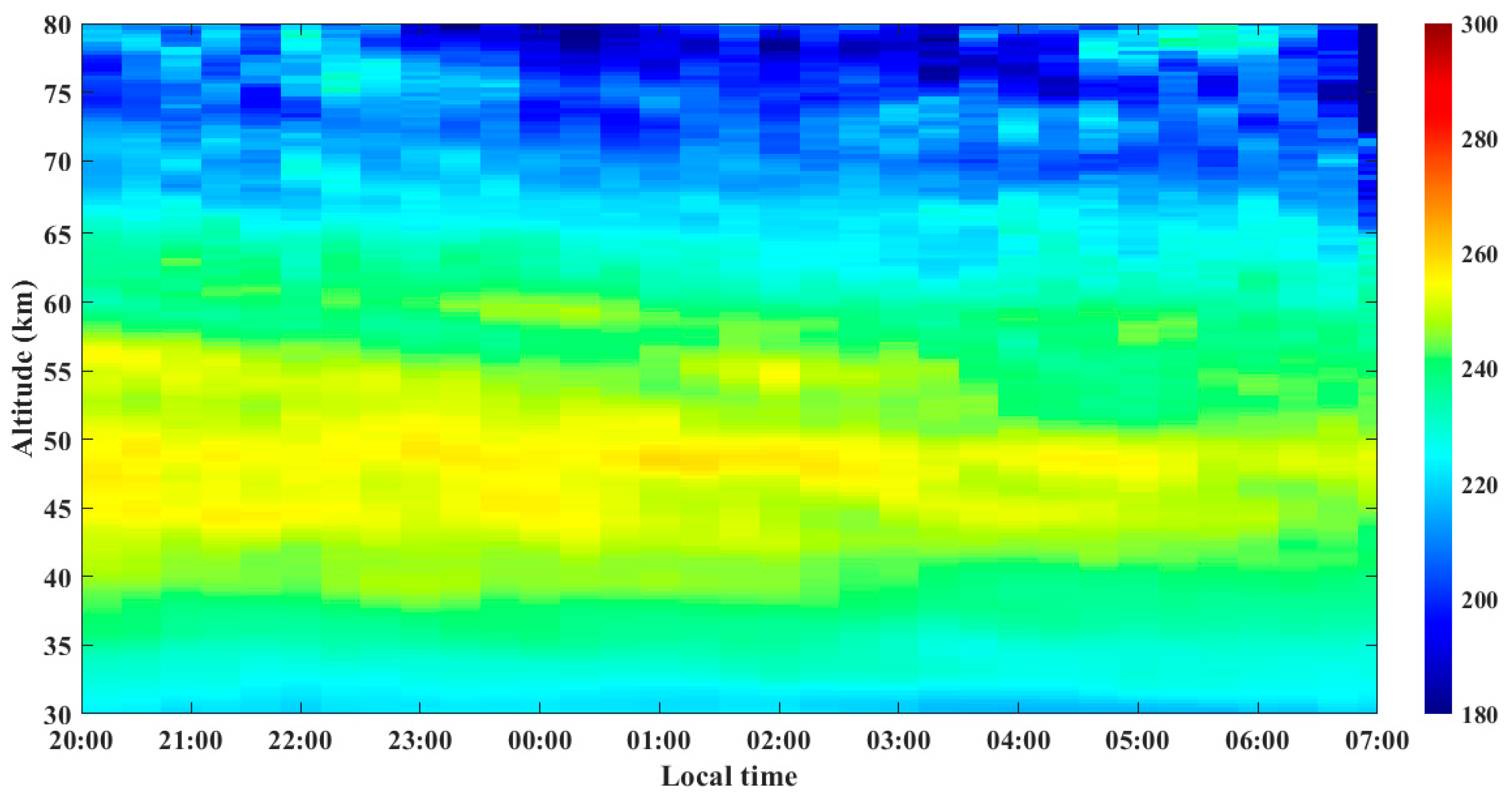
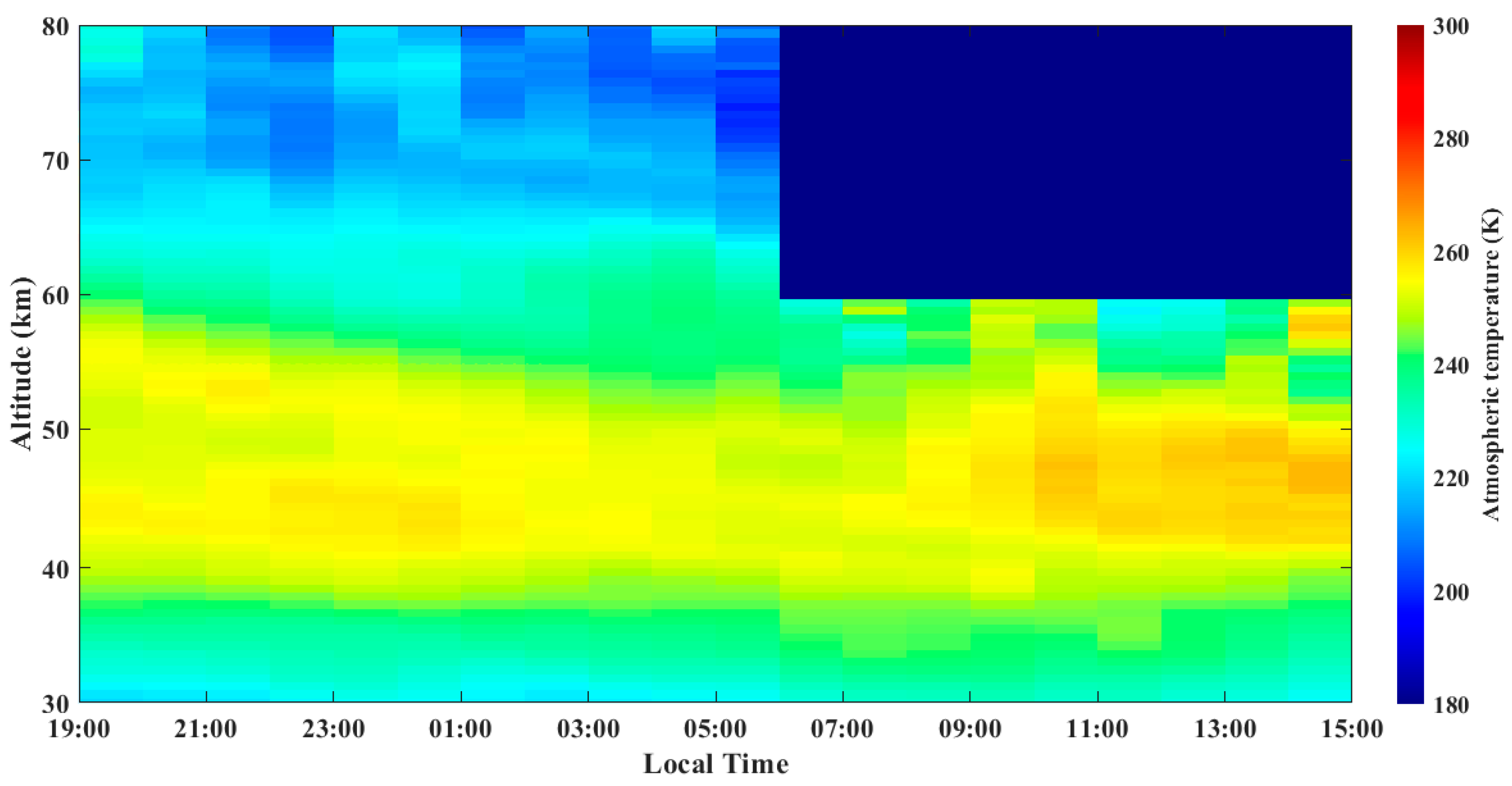
4.2. Continuous Atmospheric Temperature Distribution in the Middle Atmosphere
5. Conclusions
Author Contributions
Funding
Institutional Review Board Statement
Informed Consent Statement
Data Availability Statement
Acknowledgments
Conflicts of Interest
References
- Friedman, J.S.; Chu, X. Nocturnal temperature structure in the mesopause region over the Arecibo Observatory (18.35 N, 66.75 W): Seasonal variations. J. Geophys. Res. Atmos. 2007, 112, D14107. [Google Scholar] [CrossRef]
- McClinton, C.R.; Rausch, V.L.; Nguyen, L.T.; Sitz, J.R. Preliminary X-43 flight test results. Acta Astronaut. 2005, 57, 266–267. [Google Scholar]
- Venkat Ratnam, M.; Akhil Raj, S.T.; Qian, L. Long-term trends in the low-latitude middle layer temperature and winds: Observations and WACCM-X model simulations. J. Geophys. Res. Space Phys. 2019, 124, 7320–7331. [Google Scholar] [CrossRef]
- Lübken, F.J.; Baumgarten, G.; Hildebrand, J.; Schmidlin, F.J. Simultaneous and co-located wind detections in the middle layer by lidar and rocket-borne techniques. Atmos. Detect. Tech. 2016, 9, 3911–3919. [Google Scholar]
- Russell, J.M., III; Mlynczak, M.G.; Gordley, L.L.; Tansock, J.J., Jr.; Esplin, R.W. Overview of the SABER experiment and preliminary calibration results. Opt. Spectrosc. Tech. Instrunxentation Atmos. Space Res. III 1999, 3756, 277–288. [Google Scholar]
- Feng, W.; Marsh, D.R.; Chipperfield, M.P.; Janches, D.; Höffner, J.; Yi, F.; Plane, J.M. A global atmospheric model of meteoric iron. J. Geophys. Res. Atmos. 2013, 118, 9456–9474. [Google Scholar]
- Hedin, A.E.; Mayr, H.G.; Reber, C.A.; Spencer, N.W.; Carignan, G.R. Empirical model of global thermospheric temperature and composition based on data from the Ogo 6 quadrupole mass spectrometer. J. Geophys. Res. 1974, 79, 215–225. [Google Scholar] [CrossRef]
- Waters, J.W.; Froidevaux, L.; Harwood, R.S.; Jarnot, R.F.; Pickett, H.M.; Read, W.G.; Siegel, P.H.; Cofield, R.E.; Filipiak, M.J.; Flower, D.; et al. The Earth observing system microwave limb sounder (EOS MLS) on the aura Satellite. IEEE Trans. Geosci. Remote Sens. 2006, 44, 1075–1092. [Google Scholar] [CrossRef]
- Cook, K.L.; Wilczynski, P.; Fong, C.-J.; Yen, N.L.; Chang, G. The Constellation Observing System for Meteorology Ionosphere and climate follow-on mission. In Proceedings of the 2011 Aerospace Conference, Big Sky, MT, USA, 5–12 March 2011; IEEE: New York, NY, USA, 2011. [Google Scholar]
- Li, Y.; Lin, X.; Yang, Y.; Xia, Y.; Xiong, J.; Song, S.; Liu, L.; Chen, Z.; Cheng, X.; Li, F. Temperature characteristics at altitudes of 5-80 km with a self-calibrated Rayleigh-rotational Raman lidar: A summer case study. J. Quant. Spectrosc. Radiat. Transf. 2017, 188, 94–102. [Google Scholar] [CrossRef]
- Wu, Y.; Hu, H.; Hu, S.; Zhou, J.; Zhang, M. Rayleigh Scattering Lidar Detection of Atmospheric Temperature in the Lower Stratosphere and Mesosphere. Atmosp. Sci. 2002, 26, 23–29. [Google Scholar]
- Martucci, G.; Navas-Guzmán, F.; Renaud, L.; Romanens, G.; Gamage, S.M.; Hervo, M.; Jeannet, P.; Haefele, A. Validation of pure rotational Raman temperature data from the Raman Lidar for Meteorological Observations (RALMO) at Payerne. Atmos. Detect. Tech. 2021, 14, 1333–1353. [Google Scholar] [CrossRef]
- Alpers, M.; Eixmann, R.; Fricke-Begemann, C.; Gerding, M.; Höffner, J. Temperature lidar detections from 1 to 105 km altitude using resonance, Rayleigh, and Rotational Raman scattering. Atmos. Chem. Phys. 2004, 4, 793–800. [Google Scholar] [CrossRef]
- Kaifler, B.; Büdenbender, C.; Mahnke, P.; Damm, M.; Sauder, D.; Kaifler, N.; Rapp, M. Demonstration of an iron fluorescence lidar operating at 372 nm wavelength using a newly-developed Nd: YAG laser. Opt. Lett. 2017, 42, 2858–2861. [Google Scholar] [CrossRef] [PubMed]
- Zhang, Y.; Yi, F.; Kong, W.; Yi, Y. Slope characterization in combining analog and photon count data from atmospheric lidar measurements. Appl. Opt. 2014, 53, 7312–7320. [Google Scholar] [CrossRef] [PubMed]
- Long, D.A. The Raman Effect: A Unified Treatment of the Theory of Raman Scattering by Molecules; John Wiley & Sons Ltd.: New York, NY, USA, 2002. [Google Scholar]
- Penney, C.M.; Peters, R.L.S.; Lapp, M. Absolute rotational Raman cross sections for N2, O2, and CO2. J. Opt. Soc. Am. 1974, 64, 712–716. [Google Scholar] [CrossRef]
- Kobayashi, T.; Taira, T.; Yamamoto, T.; Hori, A.; Kitada, T. Rotational Raman lidar for lower tropospheric temperature profiling. In Proceedings of the 16th International Laser Radar Conference, Cambridge, MA, USA, 20–24 July 1992. [Google Scholar]
- Weitkamp, C. Lidar, Range-Resolved Optical Remote Sensing of the Atmosphere; Springer: Berlin/Heidelberg, Germany, 2005. [Google Scholar]
- Bucholtz, A. Rayleigh-scattering calculations for the terrestrial atmosphere. Appl. Opt. 1995, 34, 2765–2773. [Google Scholar] [CrossRef] [PubMed]
- Fang, Z.; Yang, H.; Li, C.; Kuang, Z.; Xu, X.; Song, R.; Jin, H.; Zhao, M. Characterization of the middle and upper atmosphere temperatures by Rayleigh scattering Lidar. Instrum. Sci. Technol. 2023, 52, 13–25. [Google Scholar] [CrossRef]


| Technical Index | Performance Parameter |
|---|---|
| Wavelength (nm) | 355 |
| Single pulse energy (mJ) | 600 |
| Laser linewidth (MHz) | 200 |
| Laser divergence angle (mrad) | 0.5 |
| Beam Expansion Factor | 6.75 |
| Telescope aperture (mm) | 1000 |
| Viewing angle of telescope (mrad) | 0.3 |
| Filter 1 central wavelength (nm) | 354.7 |
| Filter 1 bandwidth (nm) | 0.3 |
| Low J filter central wavelength (nm) | 354.05 |
| Low J filter bandwidth (nm) | 0.3 |
| High J filter central wavelength (nm) | 353.2 |
| High J filter bandwidth (nm) | 0.5 |
| Filter 2 central wavelength (nm) | 354.7 |
| Filter 2 bandwidth (nm) | 0.15 |
| F-P central wavelength (nm) | 354.7 |
| F-P bandwidth (pm) | 10 |
| Sampling precision (MHz) | 150 |
| Indicator Name | Performance Parameter |
|---|---|
| Effective aperture (mm) | 50.8 |
| Free Spectral Range (pm) | 90 |
| 3 dB bandwidth (pm) | 10 |
| Peak transmittance (parallel beam) | >70% |
| Mirror optical reflectance | 78% |
Disclaimer/Publisher’s Note: The statements, opinions and data contained in all publications are solely those of the individual author(s) and contributor(s) and not of MDPI and/or the editor(s). MDPI and/or the editor(s) disclaim responsibility for any injury to people or property resulting from any ideas, methods, instructions or products referred to in the content. |
© 2025 by the authors. Licensee MDPI, Basel, Switzerland. This article is an open access article distributed under the terms and conditions of the Creative Commons Attribution (CC BY) license (https://creativecommons.org/licenses/by/4.0/).
Share and Cite
Wang, B.; Li, C.; Deng, Q.; Wu, D.; Wang, Z.; Yang, H.; Xing, K.; Wang, Y. Research on the Detection of Middle Atmosphere Temperature by Pure Rotating Raman–Rayleigh Scattering LiDAR at Daytime and Nighttime. Photonics 2025, 12, 590. https://doi.org/10.3390/photonics12060590
Wang B, Li C, Deng Q, Wu D, Wang Z, Yang H, Xing K, Wang Y. Research on the Detection of Middle Atmosphere Temperature by Pure Rotating Raman–Rayleigh Scattering LiDAR at Daytime and Nighttime. Photonics. 2025; 12(6):590. https://doi.org/10.3390/photonics12060590
Chicago/Turabian StyleWang, Bangxin, Cheng Li, Qian Deng, Decheng Wu, Zhenzhu Wang, Hao Yang, Kunming Xing, and Yingjian Wang. 2025. "Research on the Detection of Middle Atmosphere Temperature by Pure Rotating Raman–Rayleigh Scattering LiDAR at Daytime and Nighttime" Photonics 12, no. 6: 590. https://doi.org/10.3390/photonics12060590
APA StyleWang, B., Li, C., Deng, Q., Wu, D., Wang, Z., Yang, H., Xing, K., & Wang, Y. (2025). Research on the Detection of Middle Atmosphere Temperature by Pure Rotating Raman–Rayleigh Scattering LiDAR at Daytime and Nighttime. Photonics, 12(6), 590. https://doi.org/10.3390/photonics12060590