Abstract
System architecture was developed to solve the issues of short pupil distance and mismatch between the simulated wavelength range and the sensor in the simulator of small targets in space. The system consists of Liquid Crystal on Silicon (LCOS), a Polarizing Beam Splitter (PBS), a dual free-form surface-illumination system, and a long-exit-pupil-distance projection system. The innovatively designed long exit pupil distance projection system can achieve an exit pupil distance of 1250 mm, covering the visible and near-infrared bands from 400 to 950 nm. The dual free-form surface-illumination system reaches a divergence angle of ±4.3° and an illumination non-uniformity of 4.7%. Experimental validation shows that the system’s star position error is better than −3.94″, and the angular distance error between stars does not exceed −7.69″. The radiation simulation accuracy for stars ranging from magnitude 3 to 6 is between −0.049 and 0.085 magnitudes, demonstrating high-precision simulation capabilities for both geometric and radiation characteristics. The research results set a critical theoretical foundation for the development of high-fidelity space target simulators, and the proposed dual free-form surface-design method and wide-spectrum aberration compensation technology provide a new paradigm for precision optical system design.
1. Introduction
With the rapid advancement of deep-space exploration technology [1], star trackers, as the core components of spacecraft attitude control systems, are increasingly demanding higher measurement accuracy [2]. Consequently, the performance requirements for space small-target simulators, which are essential for ground-based calibration of star trackers, have also been continuously improving.
Currently, space small-target simulators primarily use Thin-Film Transistor Liquid Crystal Displays (TFT-LCDs) [3], Digital Micromirror Devices (DMDs) [4], and reflective Liquid Crystal on Silicon (LCOS) [5] as spatial light modulators. Between 2019 and 2020, Li Guangxi [6], Dai Yu [7], and Liu Xinran [8] designed space small-target simulators based on TFT-LCDs (exit pupil distance of 200 mm), DMDs (exit pupil distance of 60 mm), and LCOS (exit pupil distance of 40 mm), respectively. However, the entrance pupil of star trackers is typically deep, and the external baffle of the optical tube is long. During performance calibration, the working distance between the star tracker and the space small-target simulator often exceeds 1 m [9]. The short exit pupil distance of current simulators cannot meet the optical pupil-matching principle, thereby affecting simulation accuracy. To solve this problem, researchers have improved the accuracy of space small-target simulators by correcting simulation errors. For example, Xu Da et al. [10] developed a star point error correction model based on wavefront aberration analysis, achieving star position accuracy better than 10″. Sun Gaofei et al. [11] proposed a star position correction method considering the effects of distortion, coma, and field curvature, reducing the maximum star position error to 10.75″. Yun Zhikun et al. [12] introduced a starlight emission accuracy compensation method based on star point focal length traversal, further improving star position accuracy. However, these methods still cannot fundamentally resolve the issue of optical pupil mismatch caused by the short exit pupil distance.
Additionally, in the visible light spectrum, star trackers are susceptible to background radiation caused by sunlight scattering [13,14], which makes it difficult to realize positioning and navigation. Due to the higher efficiency of positioning and navigation using near-infrared light bands during the day compared to visible light bands [15], star trackers are gradually expanding their spectral range to the visible and near-infrared light bands. This requires small space target simulators to extend the band range from the traditional 500–800 nm to cover both visible and near-infrared light bands [16,17] in order to solve the problem of mismatched bands with star trackers.
Therefore, this paper proposes a long-exit-pupil-distance dynamic space small-target simulation system architecture to address the problems of the short-exit pupil distance of the space small-target simulator and the mismatch of the simulation band. A dynamic space target-simulation system was developed, which consists of a long-exit-pupil-distance projection optical system and a double free-form surface-illumination optical system. The system can ensure the space small-target simulator maintains good imaging quality of the spatial small-target simulator with long pupil distance, wide band, and high-precision ground simulation of spatial small targets.
2. The Overall Architecture of a Dynamic Space Small-Target Simulation System with Long-Exit Pupil Distance
The long-exit-pupil-distance dynamic space small-target simulation system uses a long-exit-pupil-distance projection optical system to project the target image carried by a target display device placed on its focal plane [18], simulating small space targets at infinity. The target display devices often used are TFT-LCDs, DMDs, and LCOS [19]. Among these, the low aperture rate of TFT-LCDs and the insufficient utilization of optical energy make it difficult to achieve the target wide-energy dynamic-range modulation [20]. The individual micromirror size and neighbouring micromirror spacing of DMDs are large and still lack the ability to simulate targets with high accuracy [21,22]. LCOS is characterized by smaller individual pixel size, closer pixel spacing, larger aperture utilization, and higher light energy utilization [23]. Therefore, LCOS is selected as the target display device for the dynamic spatial small-target simulation system. However, LCOS can only modulate the beam in the S-polarized state, requiring a dual free-form surface-illumination optical system and a polarizing beam splitter (PBS) for illumination. Therefore, the overall architecture of the long-exit-pupil-distance dynamic spatial small-target simulation system constructed in this paper consists of a long-exit-pupil-distance projection optical system, LCOS, a polarizing beam splitting prism (PBS), and a double free-form illumination optical system, as shown in Figure 1.
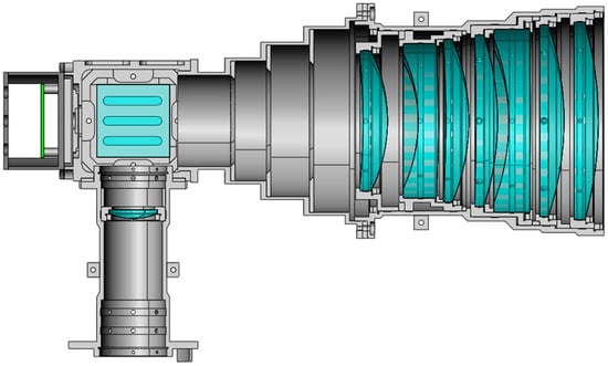
Figure 1.
General architecture of the space small-target simulation system.
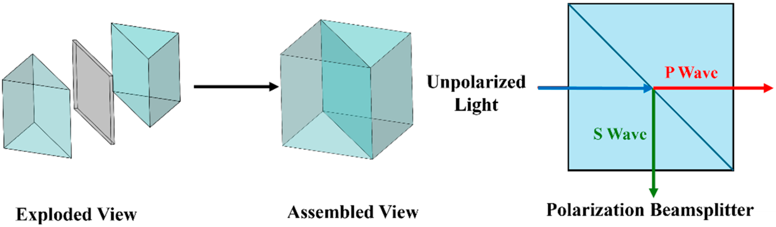
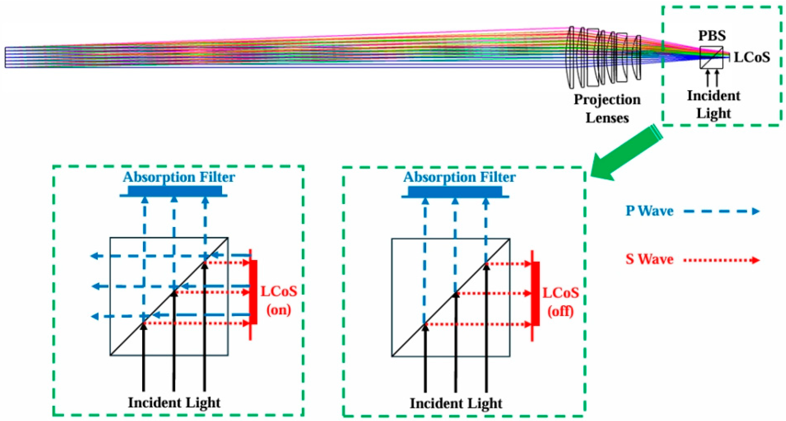
The PBS is composed of a pair of high-precision right-angle prisms bonded together [24], with a polarized spectroscopic dielectric film coated at the bonded interfaces. Non-polarized light is incident at the Brewster angle and split into two perpendicular linearly polarized beams [25]. The P-wave, parallel to the plane of incidence, can be transmitted through the prism, while the S-wave, which is perpendicular to the plane of incidence, is reflected by the prism, and the working principle is shown in Figure 2. The non-polarized light emitted from the double free-form illumination optical system is polarized by the PBS prism to form line-polarized light P and S waves, which are reflected onto the LCOS. When the LCOS is in the bright state, it modulates the S-wave into a P-wave, which is reflected and then transmitted to the projection optical system through the PBS [26]; the P-wave cannot be modulated by the LCOS and is directly reflected by the protective glass, forming a stray spot [27]. At the same time, the deflection efficiency of the PBS prism is related to the numerical aperture angle of the outgoing beam of the double free-form illumination optical system; the larger the numerical aperture angle, the more P-waves are mixed with S-waves. Therefore, to avoid this problem, the emitted beam from the double free-form illumination optical system should be incident into the PBS with a small numerical aperture angle. The working optical path of the dynamic spatial small-target simulation system with a long-exit pupil distance is shown in Figure 3.
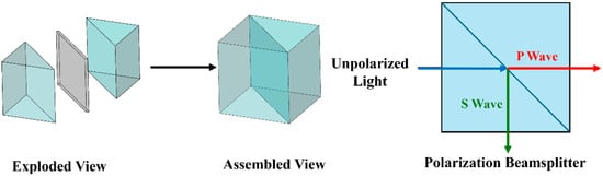
Figure 2.
Diagram of PBS operation.
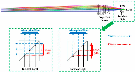
Figure 3.
Working optical path of the dynamic spatial small-target simulation system with long-exit pupil distance.
3. Design of the Long-Exit-Pupil-Distance Projection Optical System
The long-exit-pupil-distance dynamic space small-target simulation system operates in the wavelength range of 450 nm~900 nm, with docked target sensitize having a field of view of 4° and an entry pupil diameter of 45 mm. The pupil diameter of the long-pupil projection optics is also set at 45 mm to ensure optical pupil articulation. At the same time, the pupil distance of the long-exit-pupil-distance projection optics is set to 1250 mm in order to avoid the interference of the mechanical structure between the long-exit-pupil-distance dynamic spatial small-target simulation system and the target sensitizer. The index parameters of the long-exit-pupil-distance projection optical system are shown in Table 1.

Table 1.
Indicator parameters of the long-exit-pupil-distance projection optical system.
In this paper, the LCOS is selected as Kopin Corporation’s SXGA-R5 model, with a resolution of 2048 × 1536, an image element size of 8.3 μm, and an effective light-emitting size of 10.63 mm, and the focal length of the long-exit-pupil-distance projection optical system can be obtained as 304.41 mm, according to the following equation:
The focal length of the long-exit-pupil-distance projection optical system can be obtained as 304.41 mm. Considering that the long-exit-pupil-distance projection optical system is characterized by a long-exit pupil distance, the Elf eyepiece structure optical system with small aberration, large field of view, and telson external position was selected as the initial structure [28]. The image quality of the optimized long-exit-pupil-distance projection optical system is shown in Figure 4.

Figure 4.
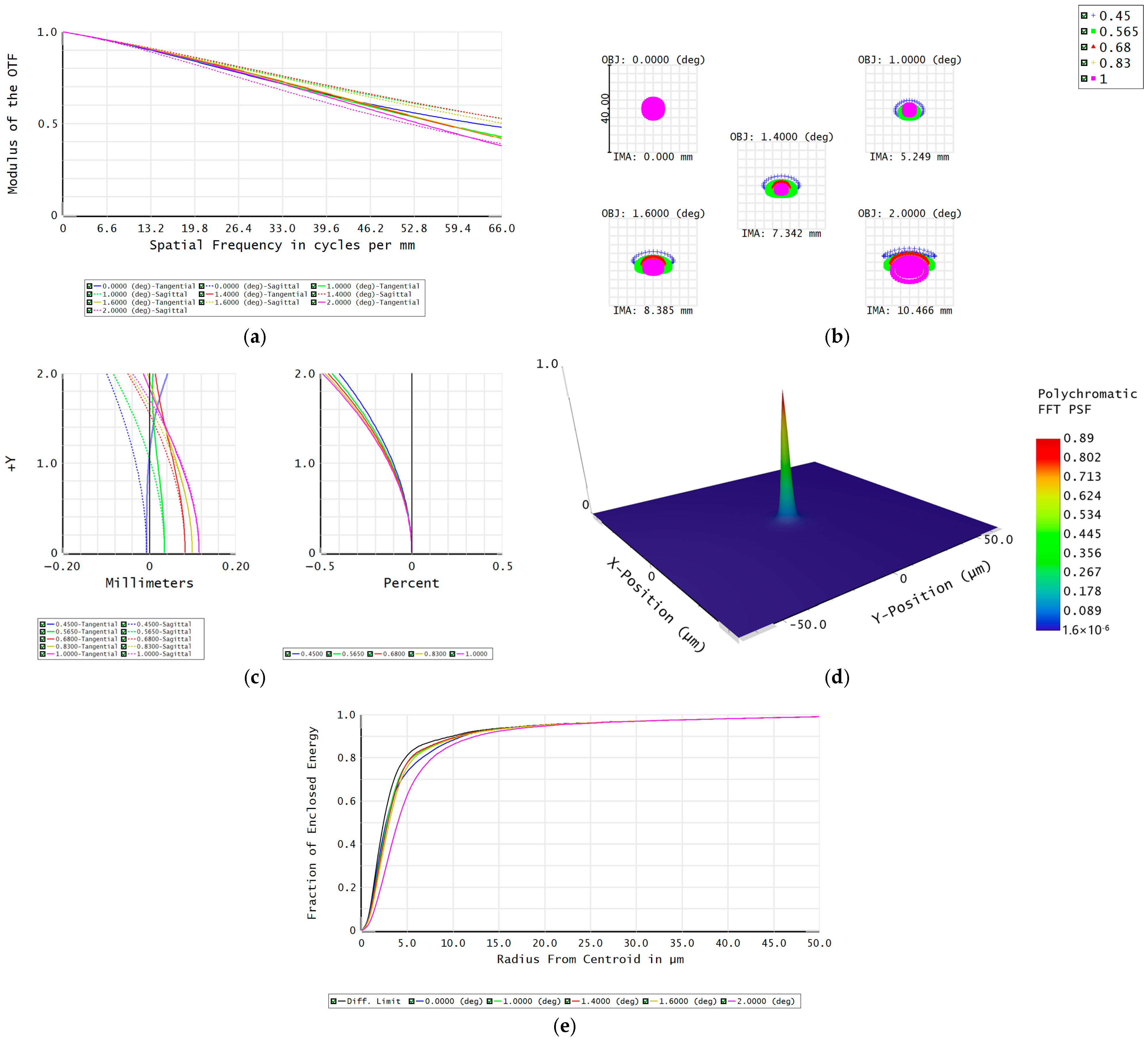
Image quality of the long-exit-pupil-distance projection optical system. (a) Transfer function. (b) Spot diagram. (c) Field curvature and distortion. (d) Point spread function. (e) Energy distribution diagram of the optical system.
It can be concluded from Figure 4a that the MTF value of the whole field of view is better than 0.4 when the Nyquist frequency is 61 , and the imaging quality of the system is good. Figure 4b shows that the radius of the dispersion spot in each field of view is less than one image element size, indicating that the image point diffusion size of the system is controlled in a small range, which is in accordance with the design requirements of the system. From Figure 4c, it can be seen that the maximal field curvature is 0.13 mm, and the maximal aberration is 0.46%, which meets the design requirement of less than 1%. Figure 4d indicates that the energy centre of the imaging point is basically the same as the centre of mass, and the imaging quality is good. Figure 4e demonstrates that the average value of the energy concentration of the optical system within one pixel under the full field-of-view reaches more than 82%, which is close to the diffraction limit, indicating that the energy entering into the optical system has been fully utilized.
4. Design of the Double Free-Form Surface-Illumination Optical System
The double free-form surface-illumination optical system serves to provide LCOS with a uniform illumination beam covering 450 nm–900 nm with small aperture angles. The design of the dual free-form surface-illumination optical system is divided into three parts: selection and arrangement of the light sources, initial structural design principles of the dual free-form surface-illumination optical system, and optimization and simulation [29,30].
4.1. LED Selection and Arrangement
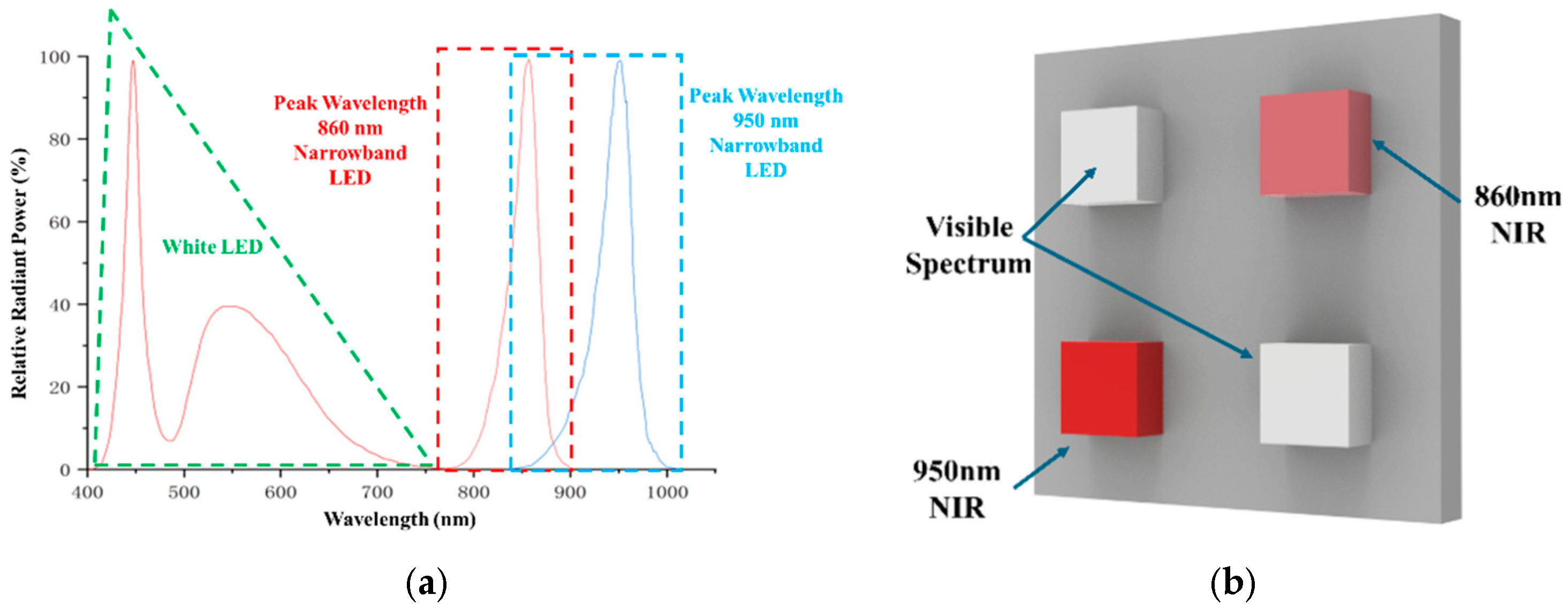
To ensure that the wavelength range of the light source can cover 450 nm–900 nm, white LEDs with a wavelength range of 400 nm–780 nm are selected. In addition, two narrow-band infrared LEDs with peak wavelengths of 860 nm and 950 nm are used to cover the wavelength range of 830 nm–1010 nm [31]. The spectral curves of these three types of LEDs are shown in Figure 5a. The arrangement of the LED light sources is as follows: two white LEDs are placed on one diagonal, and two types of infrared LEDs are placed on the other diagonal, as shown in Figure 5b.
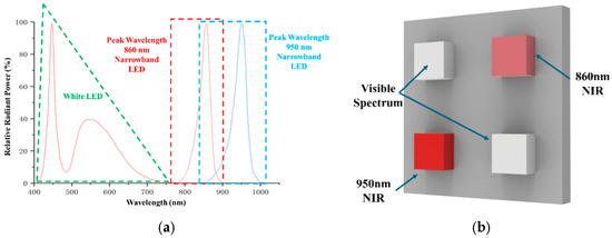
Figure 5.
Spectral curve and arrangement form of the LEDs. (a) Three LED spectral curves. (b) Schematic diagram of the LED arrangement form.
4.2. Principles of the Initial Structural Design of the Double Free-Form Surface-Illumination Optical System
To constrain the beam angle and control the uniformity of the dual free-form surface-illumination optical system, this work adopts a transmissive-total reflective secondary lens composed of an incident rotating refractive surface and an incident rotating total reflective surface. These two free-form surfaces are designed to optimize the beam divergence angle and illumination uniformity.
4.2.1. Design of the Incident Rotating Refracting Surfaces
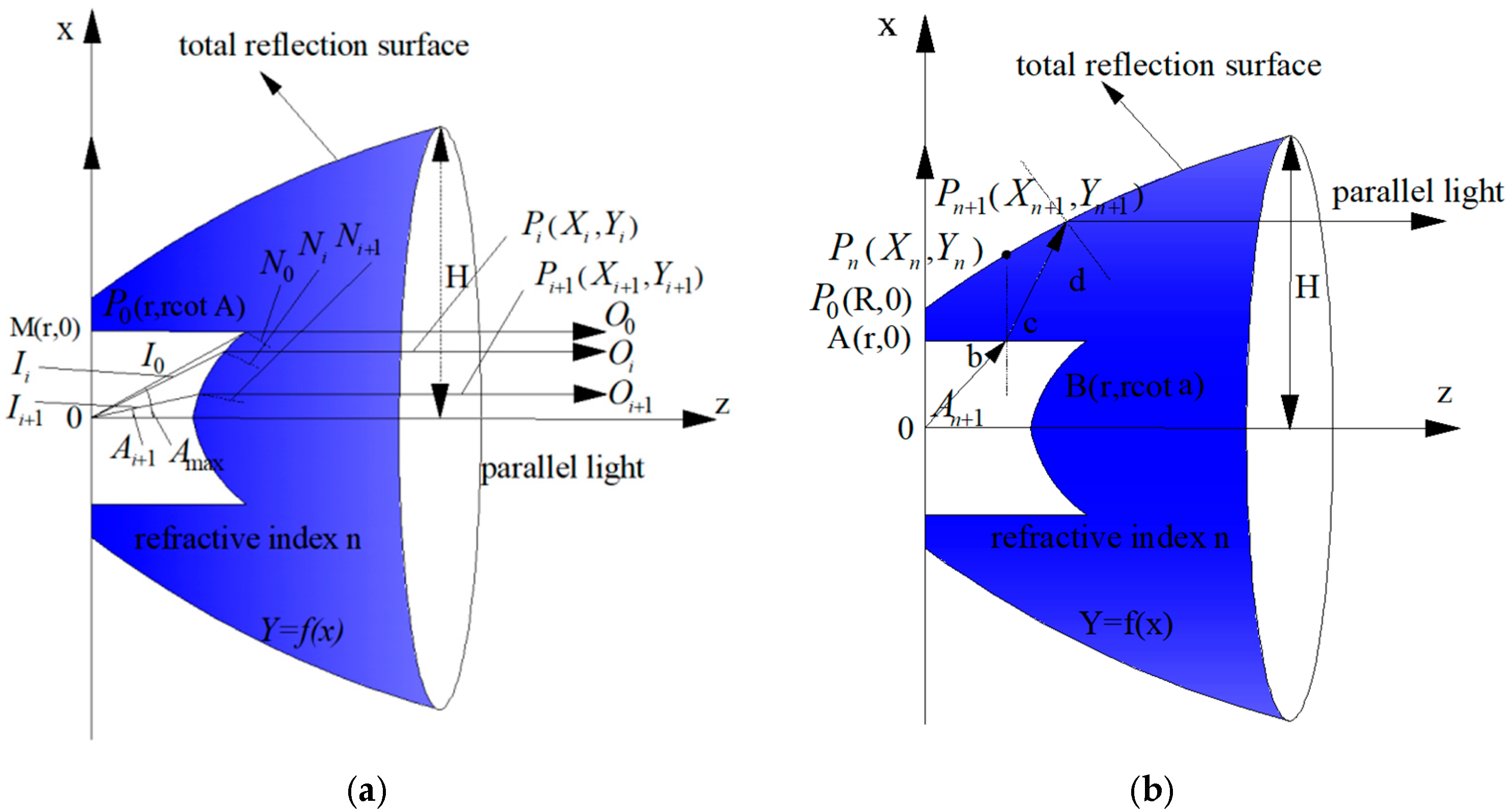
The incident rotating refractive surface is located close to the centre of the LED light source. Therefore, a coordinate system is set up with the position of the LED light source as the origin, the central axis of the system is the z-axis, and the radial axis is the x-axis. The light from the LED light source is transformed into parallel axis light after passing through the incident rotating refractive surface. Meanwhile, due to the rotational symmetry of the incident rotating refractive surface, only the curve on the cross-section of the incident rotating refractive surface is required. The design principle of the incident rotating refractive surface is shown in Figure 6a.

Figure 6.
Principle of optimizing the transmission-total reflection secondary lens. (a) Principle of the design of the incident rotating refractive surfaces. (b) Principle of the design of the incident rotating total reflection surfaces.
Let and represent the unit vectors of the incident and outgoing rays, respectively, and is the normal vector of the refraction point. The refractive index of the system material is , the maximum radius of the refractive plane of rotation is , and the angle of demarcation is . Divide equally into N equal parts, i.e., , . The coordinates of are , . The normal vector of can be found by Snell’s law.
denotes the intersection between a ray of light incident at angle and a tangent plane passing through point .
The coordinates of point can be obtained from Equations (2) and (3). Following this method the coordinates of any subsequent point on the curve , can be calculated
4.2.2. Design of the Incident Rotating Total Reflection Surface
The incident rotating total reflection surface is located on the outer side away from the LED light source. It is also required that the light emitted by the LED light source is reflected by the incident rotating total reflection surface and transformed into light parallel to the z-axis. The design principle of the incident rotating total reflection surface is shown in Figure 6b.
The light ray undergoes total reflection in the incident total reflection rotating surface; according to the law of reflection, the equation of the tangent line located at is as follows:
when the surface partition is sufficiently fine, it can be assumed that the posterior of are also on that tangent. The equation of the incident line located at is as follows:
The coordinates of any on the curve lying at the intersection of the two lines defined by Equations (5) and (6) can be obtained by solving the system of equations.
4.3. Simulation of the Double Free-Form Surface-Illumination Optical System
In this study, the divergence angle of the selected LED light sources was set at ±60°. Taking the irradiance uniformity of the double free-form surface-illumination optical system better than 95% and the divergence angle of the light beams better than ±5° as the conditions, the initial structure of the double free-form surface-illumination optical system was obtained using the Lighttools software illustrated in Section 4.2. The incident rotating refractive surface and the incident rotating total reflection surface are regarded as variables to optimize the irradiance energy distribution and the light distribution curves. Taking the light distribution curve as the optimization objective, the double free-form surface-lighting optical system [32] was optimized to obtain the simulated optical path, irradiated surface energy distribution, and light distribution curve of the double free-form surface-lighting optical system, as shown in Figure 7.
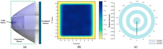
Figure 7.
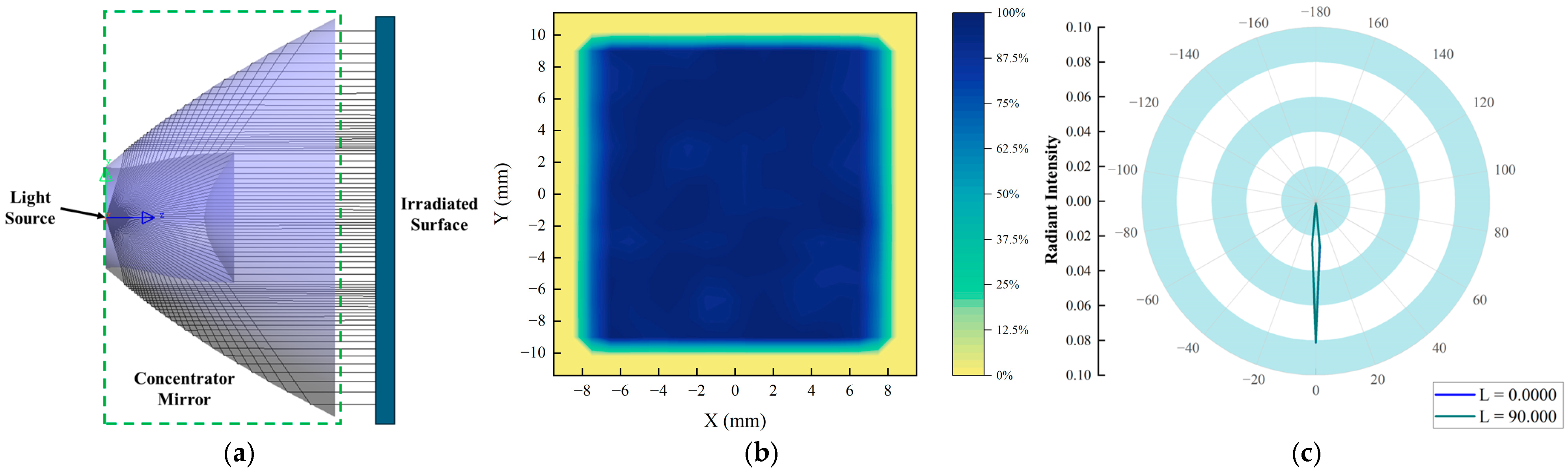
Simulation results of the double free-form surface-illumination optical system. (a) Simulated optical path of double free-form surface-illumination optical system. (b) Irradiated surface energy distribution. (c) Light distribution curves.
Figure 7a shows the simulated optical path of the double free-form illumination optical system. The light emitted from the LED light source travels onto the irradiated surface through the incident rotating refractive surface and the incident rotating total reflection surface. Figure 7b displays the normalised energy distribution of the double free-form illumination optical system on the irradiated surface. The uniformity of this distribution can be calculated using the method described in [18].
where is the maximum light intensity and is the minimum light intensity. Figure 7c shows the light distribution curve, which indicates that the divergence angle is ±4.3° after the LED light source passes through the incident rotating refractive surface and the incident rotating total reflection surface.
5. Experiments and Tests
5.1. Experimental Platform and Experimental Design
Since the performance of the long-exit-pupil-distance dynamic space small-target simulation system tuned by actual processing differs from the theoretical results [33], it is necessary to conduct accuracy correction experiments firstly, followed by performance verification experiments. The experimental platform is built using a theodolite, an illuminometer, and a dynamic spatial small-target simulation system with long-exit pupil distance, as shown in Figure 8.
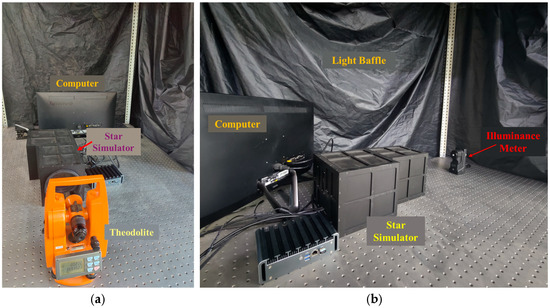
Figure 8.
Experimental platform. (a) Star simulator angular position calibration experiment (b) Star simulator radiometric calibration experiment.
5.2. Accuracy Correction Experiment
Equally spaced 10 × 10 grids are divided on the LCOS of the long-exit-pupil-distance dynamic spatial small-target simulation system. LCOS pixels at the intersections of the illuminated grids are used as test sample points within the field of view of the long-exit-pupil-distance dynamic spatial small-target simulation system.
The theodolite is used to measure the azimuth and pitch angles of the test sampling point and those of the field-of-view centre point as ; the position of the single star at the measured test sampling point can be expressed as follows:
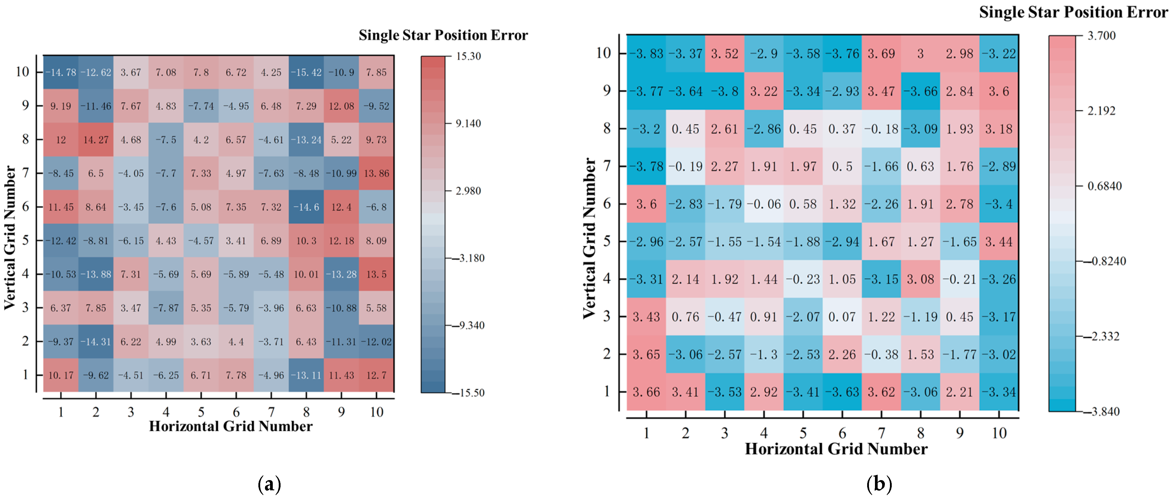
By comparing with the theoretical single star positions of the test points, a heat map of the single star position errors of the test sampling points without accuracy correction is derived, as shown in Figure 9a.
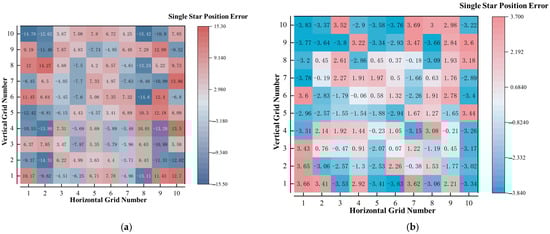
Figure 9.
Heat map of single star position error before and after correction. (a) Heat map of uncorrected single star position error. (b) Heat map of single-star position error after correction.
On this basis, the least squares fitting method [34,35,36] is applied to complete the correction of the long-exit-pupil-distance dynamic space small-target simulation system, and the heat map of the single star position error of the corrected test sampling points is shown in Figure 9b.
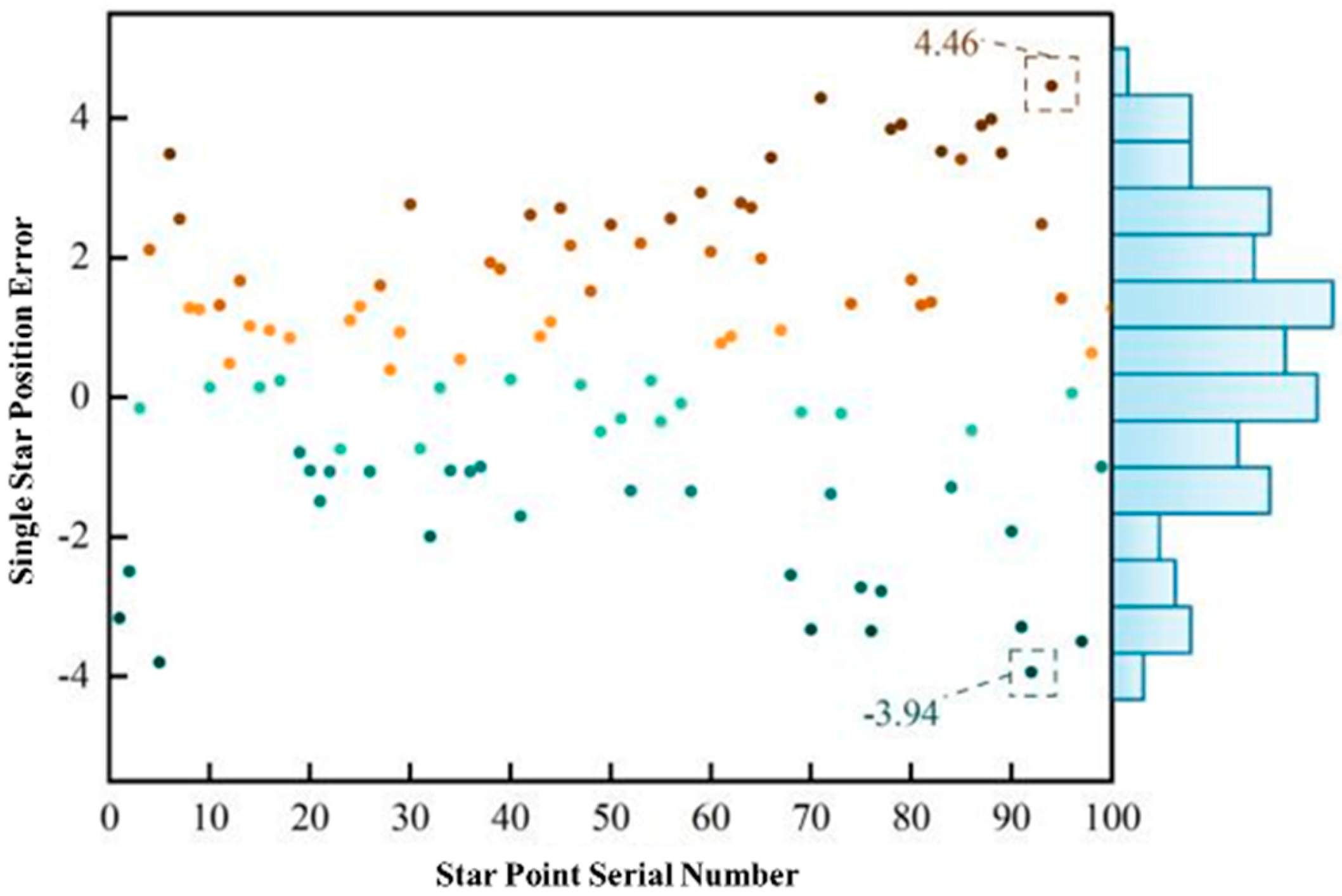
According to Figure 9, the maximum error of the corrected single star position error is −3.83″. However, since the distribution of small spatial targets has only a certain probability of coinciding with the test sampling points, it is idealized to evaluate the correction accuracy only by the accuracy of the test sampling points. Therefore, a test star map of 100 star points was constructed by randomly selecting one pixel point in each of the 10 × 10 regions to evaluate the accuracy of the long-exit-pupil-distance dynamic spatial small-target simulation system. The test results are shown in Figure 10.

Figure 10.
Distribution of single star position errors for the test star map.
According to Figure 10, the distribution of the single star position error of 100 test star points is relatively close to a normal distribution, in which the maximum value is 4.46″ and the minimum value is −3.94″. The distribution does not show a distribution relationship that is strongly correlated with the size of the field of view, which means that the location of the star points has less influence on the single star position error, and the simulation accuracy of the long-exit-pupil-distance dynamic spatial small-target simulation system has been well corrected.
5.3. Performance Verification Experiment
In order to avoid the peculiarity of the performance verification of a single star map, the performance verification experiment of the long-exit-pupil-distance dynamic space small-target simulation system uses two star maps with known star positions and magnitudes to verify the geometric feature simulation accuracy and the radiation feature simulation accuracy of the long-exit-pupil-distance dynamic space small-target simulation system. The star positions and magnitudes of the two star maps are listed in Table 2.
Table 2.
Star positions and magnitudes of the star maps.
5.3.1. Accuracy of the Geometric Feature Simulation
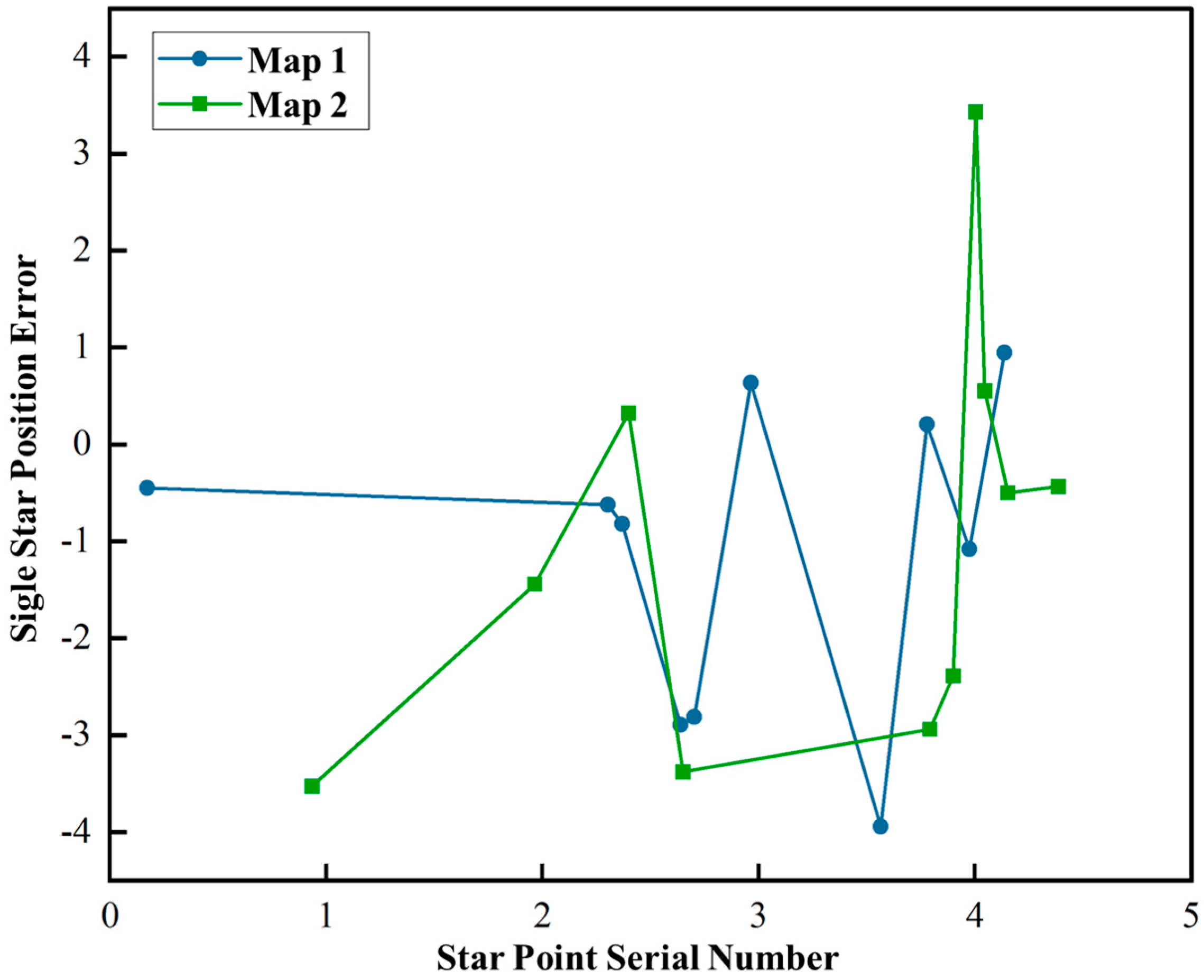
Using theodolite to measure the centre point of Star Map 1 and Star Map 2, and the azimuth and pitch angle of each star point according to Equation (7), we can obtain the simulation accuracy of the star point position of Star Map 1 and Star Map 2, as shown in Figure 11.
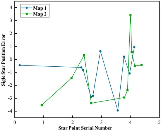
Figure 11.
Simulated accuracy of star point positions for Star Map 1 and Star Map 2.
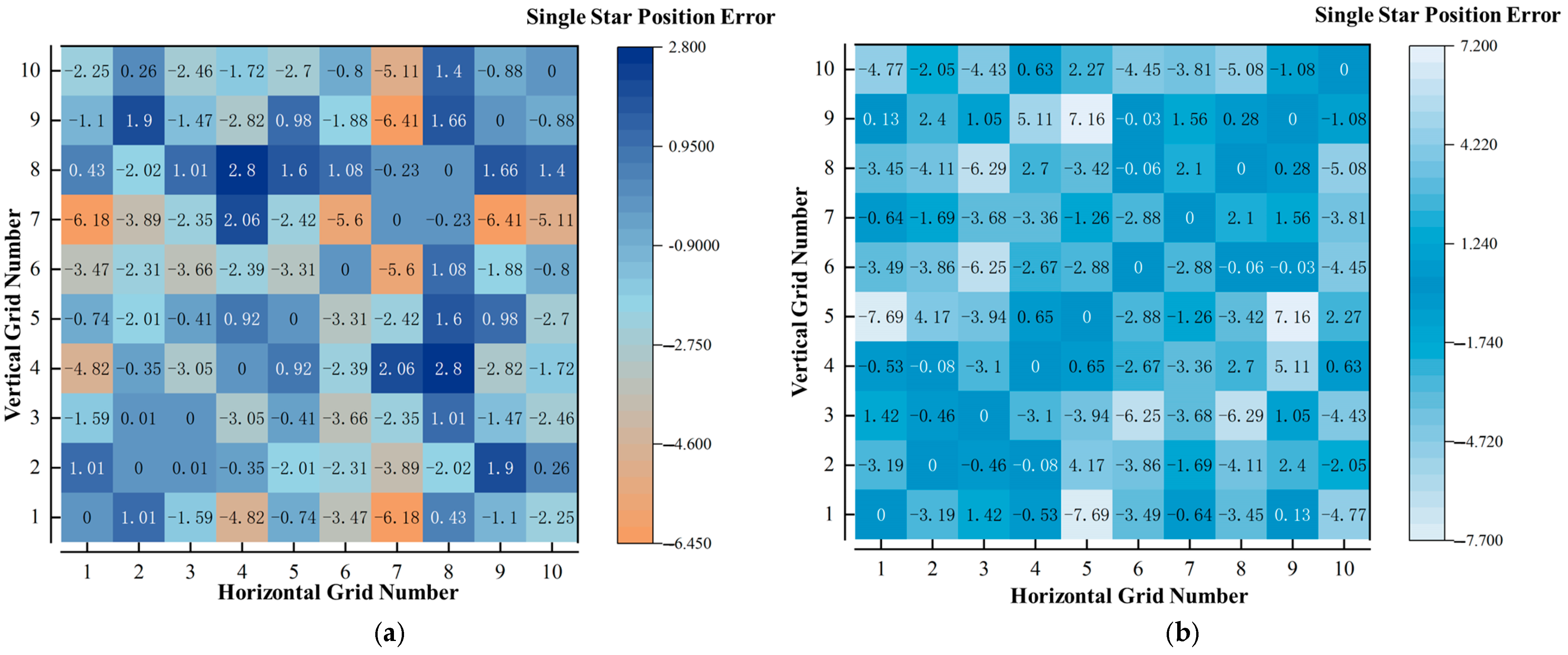
From Figure 11, it can be concluded that the star point position error distribution of Star Map 1 is between −3.94″ and 0.94″, and the star point position error distribution of Star Map 2 is between −3.52″ and 3.43″. At this point, the heat map of the interstellar angular distance error of the two star maps can be obtained according to Equation (7), as shown in Figure 12.
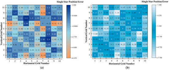
Figure 12.
Heat map of interstellar angular distance error. (a) Interstellar angular separation errors in Star Map 1. (b) Interstellar angular separation errors in Star Map 2.
From Figure 12 it can be seen that the interstellar angular separation errors are distributed between −6.41″ and 2.80″ for Star Map 1 and between −7.69″ and 7.16″ for Star Map 2.
5.3.2. Accuracy of Radiation Signature Simulation
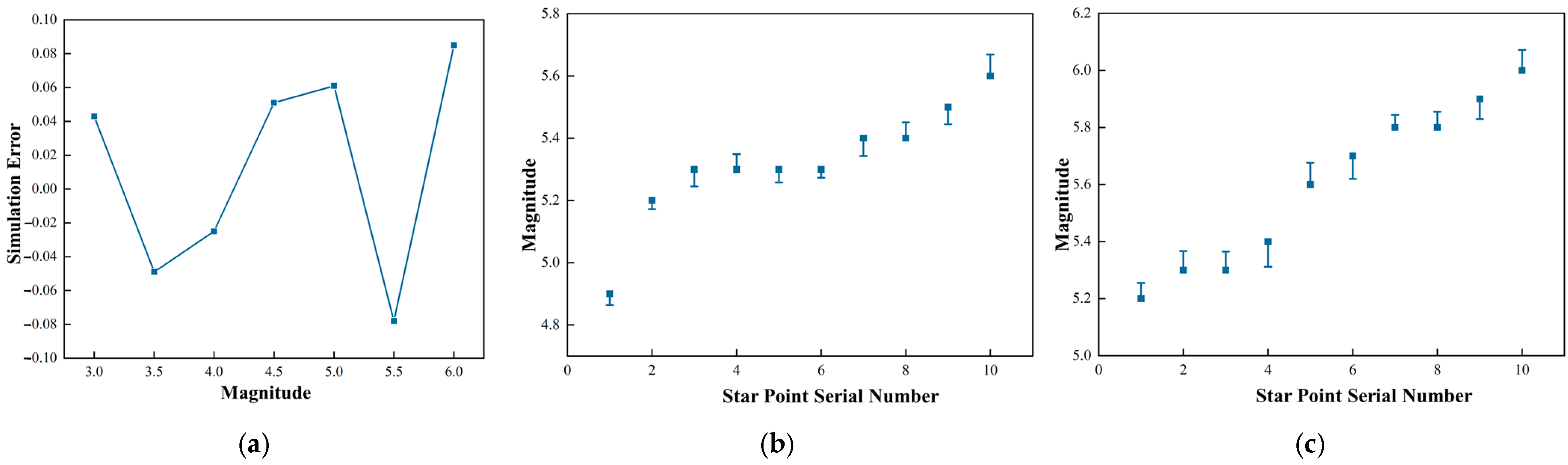
From Table 2, it can be seen that the magnitudes of the 10 stars in Star Map 1 are between 4.9 and 5.6 magnitudes, and the magnitudes of the 10 stars in Star Map 2 are between 5.2 and 6 magnitudes. Due to the superposition of energies when multiple stars are illuminated within the map, the simulation accuracy of the radiation characteristics cannot be evaluated. Therefore, this paper first selects the centre star point and uses an illuminance meter to measure it by controlling the central star point to have magnitudes of 3 to 6 and intervals of 0.5, in order to verify the accuracy of the radiation characteristic simulation system for dynamic small space targets with long pupil distance. The results are shown in Figure 13a. On this basis, the magnitude simulation errors of the star points of Star Map 1 and Star Map 2 are measured one-by-one, and the results are shown in Figure 13b,c.
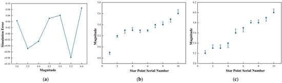
Figure 13.
Magnitude simulation errors. (a) Centre field of view magnitude simulation errors. (b) Magnitude simulation errors in Star Map 1. (c) Magnitude simulation errors in Star Map 2.
From Figure 13, it can be seen that the long-exit-pupil-distance dynamic space small-target simulation system has the ability to simulate the radiation characteristics of stars ranging from magnitude 3 to 6, and the simulation accuracy ranges between −0.049 and 0.085 magnitudes, which can realize the superposition simulation of radiation characteristics based on the simulation accuracy of the geometric characteristics.
6. Conclusions
Aiming at the problems of short-exit pupil distance and the mismatch between simulated band interval and sensitizer in the small-target simulator in space, a system architecture was constructed, which is composed of a long-pupil projection optical system, LCOS, a polarizing beam splitter prism (PBS), and double free-form surface-illumination optics, and a long-pupil projection optical system was designed covering visible and near-infrared bands (450 nm–900 nm), with a pupil exit distance of 1250 mm. At the Nyquist frequency of 61 , the MTF value of the whole field of view is better than 0.4, the aberration is less than 0.46%, and the average value of the energy concentration of the optical system in the nearest pixel of the whole field of view reaches more than 82%. Meanwhile, a double free-form surface-illumination optical system composed of an incident rotating refractive surface and an incident rotating total reflection surface was optimally designed to constrain the divergence angle and ensure the uniformity, achieving a divergence angle of ±4.3° and an inhomogeneity of 4.7%. Additionally, an experimental bench was constructed to correct the long-exit pupil distance of the dynamic spatial small-target simulation system, which in turn verified the geometric and radiative feature simulation accuracy of the system. The results show that the star point position error of the long-exit-pupil-distance dynamic space small-target simulation system is better than −3.94″, and the interstellar angular distance error is better than −7.69″; the radiation simulation accuracy for stars ranging from magnitude 3 to 6 is between −0.049 and 0.085 magnitudes, and it has the ability to simulate the superimposed geometric and radiation features, which provides basic technical support for the research of higher precision space small-target simulator.
In the future, the simulation of different star colour temperatures can be achieved by increasing the types of LED light sources and working with spectral modulation algorithms to further optimise the star chart display method, improve the dynamic performance of the star charts, and achieve a more realistic simulation of the star charts.
Author Contributions
Conceptualization, Y.L. (Yi Lu) and X.X.; Literature Review and Investigation, N.Z. and Y.L. (Yi Lu); resources, Y.L. (Yaowen Lv) and X.X.; Data Curation, Y.L. (Yi Lu); Writing—Original Draft Preparation, Y.L. (Yi Lu); Writing—Review and Editing, Y.L. (Yi Lu), X.X. and H.G.; Supervision, Y.L. (Yi Lu) and X.X.; Project Administration, Y.L. (Yi Lu). All authors have read and agreed to the published version of the manuscript.
Funding
This research received no external funding.
Institutional Review Board Statement
Not applicable.
Informed Consent Statement
Not applicable.
Data Availability Statement
The raw data supporting the conclusions of this article will be made available by the author upon request.
Conflicts of Interest
The author declares no conflicts of interest.
References
- Liu, Q.; Dong, M.; Sun, P.; Yan, B.; Wang, J.; Zhu, L. All-parameter calibration method of the on-orbit multi-view dynamic photogrammetry system. Opt. Express 2023, 31, 11471–11489. [Google Scholar] [CrossRef] [PubMed]
- Mahi, Z.; Karoui, M.S.; Keche, M. A new star detection approach for a satellite-onboard star tracker. Adv. Space Res. 2023, 72, 2336–2350. [Google Scholar] [CrossRef]
- Cao, X.; Wang, L.; Li, G.; Zheng, R. Design of projection optical system for target imaging simulator with long exit pupil distance. Curr. Opt. Photonics 2023, 7, 745–754. [Google Scholar] [CrossRef]
- Shao, H.; Wang, L.; Zhang, H.; Li, G.; Chen, Y. Design Method for Laser Target Simulator Illumination System with High Energy Utilization and High Uniformity. IEEE Photon. J. 2024, 16, 1–7. [Google Scholar] [CrossRef]
- Zhang, Q.; Xu, X.; Pan, Y.; Hu, M. Design of projection optical system for dynamic star simulator with long exit pupil distance. J. Chang. Univ. Sci. Technol. Nat. Sci. Ed. 2021, 44, 13–18. [Google Scholar]
- Li, G.; Wang, L.; Zheng, R.; Yu, X.; Ma, Y.; Liu, X.; Liu, B. Research on Partitioning Algorithm Based on Dynamic Star Simulator Guide Star Catalog. IEEE Access 2021, 9, 54663–54670. [Google Scholar] [CrossRef]
- Yu, D.; Xin, C.; Wenming, Z.; Jie, L.; Shenglin, L. Design of optical system based on DMD for simulator with large field of view and long exit pupil distance. J. Appl. Opt. 2020, 41, 891–897. [Google Scholar] [CrossRef]
- Liu, X.R.; Xu, X.P. Structural design of a small target simulator optic based on LCOS splicing. J. Chang. Univ. Sci. Technol. (Nat. Sci. Ed.) 2019, 10, 55–60. [Google Scholar]
- Cao, T.; Wang, L.Y. Design of a dynamic target simulator optical system with a large FOV and long exit pupil distance. Appl. Opt. 2024, 63, A115–A123. [Google Scholar] [CrossRef]
- Xu, D.; Zhang, G.; Sun, G. Design of star simulator with spatial background light. Chin. J. Space Sci. 2018, 38, 575–582. [Google Scholar] [CrossRef]
- Sun, G.; Ming, S.; Zhang, G.; Liu, S.; Xu, D. Correction Method of Star Position Error for Splicing Star Simulator. Acta Photon. Sin. 2021, 50, 0912006. [Google Scholar] [CrossRef]
- Yun, Z.; Zhang, J.; Zhang, Y.; Ren, T.; Chen, S.; Zhao, B.; Zhang, J.; Lin, G.; Zhang, G. Research on compensation method for starlight emission accuracy based on star point focal length traversal. Opt. Commun. 2024, 567, 130664. [Google Scholar] [CrossRef]
- Yang, S.Z.; Zhang, G.Y.; Sun, G.F.; Liu, S.; Xu, D. Design of star sensitizer performance test system with tunable background. Laser Optoelectron. Prog. 2022, 59, 2322001. [Google Scholar] [CrossRef]
- Zheng, R.; Li, C.Y.; Gao, Y.; Li, G.X.; Liu, B.; Sun, G. Design of an infrared star simulator optical system for uniform radiation at specific irradiance. J. Photonics Acta Photonica Sin. 2022, 51, 0428002. [Google Scholar] [CrossRef]
- Wang, H.; Wang, B.; Gao, Y.; Wu, S. Near-earth space star map simulation method of short-wave infrared star sensor. Infrared Phys. Technol. 2022, 127, 104436. [Google Scholar] [CrossRef]
- Sun, G.; Ming, S.; Zhang, G.; Liu, S.; Zhang, J.; Su, S.; Yang, S.; Zhang, R. Design of multi-magnitude star simulation system based on adjustable background. Optik 2020, 207, 164486. [Google Scholar] [CrossRef]
- Wu, L.; Zhang, G.; Sun, G.; Liu, S.; Yang, S.; Yang, J.; Yun, Z.; Zhao, D.; Sun, J.; Zhao, D. Optical engine optimisation for faint starlight simulation systems. Opt. Commun. 2020, 471, 125833. [Google Scholar] [CrossRef]
- Yang, S.; Zhang, Y.; Zhao, B.; Meng, Y.; Ren, D.; Zhang, J.; Sun, G.; Du, Z.; Zhang, G. Simulation method for multi-source information fusion space target. Opt. Express 2024, 32, 21820–21836. [Google Scholar] [CrossRef]
- Li, S.-H.; He, H.; Ji, Q.; Zhang, X.-H.; Li, N. Design of a dynamic star simulator with high temporal and spatial resolution. Opt. Precis. Eng. 2020, 3, 515–525. [Google Scholar]
- Kang, J.; Zheng, R.; Wang, L.; Pang, C.; Li, G. Research on the Detection Method of Projection Stellar Target Simulator. Photonics 2023, 10, 1101. [Google Scholar] [CrossRef]
- Yun, Z.; Zhang, Y.; Liu, Q.; Ren, T.; Zhao, B.; Xu, D.; Yang, S.; Ren, D.; Yang, J.; Mo, X.; et al. Research on the simulation method of a BP neural network PID control for stellar spectrum. Opt. Express 2024, 32, 38879–38895. [Google Scholar] [CrossRef] [PubMed]
- Lu, X.W.; Xu, X.P.; Pan, Y.; Zhang, L.Q.; Wang, Z.Y. Research on optical system design of star simulator. J. Changchun Univ. Sci. Technol. (Nat. Sci. Ed.) 2024, 4, 31–40. [Google Scholar]
- Zhao, D.; Zhang, G.; Xu, D.; Wang, L.; Sun, G.; Zhong, J.; Wu, L. A Diffraction Correction Method Based on Digital Mirror Device Star Simulator. Acta Photon. Sin. 2021, 50, 0912005. [Google Scholar] [CrossRef]
- Chen, N.; Yue, W.; Xu, Y.; Guo, W.; Xiao, Y.; Ren, Z.; Ding, X.; Li, M.; Xu, Y.; Wu, T.; et al. Design and simulation of a compact polarization beam splitter based on dual-core photonic crystal fiber with elliptical gold layer. Sci. Rep. 2024, 14, 18017. [Google Scholar] [CrossRef]
- Wu, L.; Wang, J.; Xia, Y.; Li, Y.; Sheng, L. Optimization of polarization balance in beam splitter films for weak star simulator. Opt. Express 2024, 32, 25304–25316. [Google Scholar] [CrossRef]
- Jing-Yi, F.F.; Tian-Xiang, Q.Q.; Yun-Han, H.H.; Zhi-Ying, L.L. A field-of-view splicing method for the optical system of a star simulator. Chin. Opt. 2021, 14, 1468–1475. [Google Scholar] [CrossRef]
- Liu, X.; Liu, S.; Zheng, J.; Wang, Y.; Li, H.; Wen, Z. Research on Optical System of Dim Target Simulator Based on Polarization Stray Light Suppression. Appl. Sci. 2024, 14, 2826. [Google Scholar] [CrossRef]
- Gao, T.; Sun, G.; Zhang, G.; Du, Z.; Liu, Q.; Deng, Q.; Chen, S.; Zhang, J. Design of Parabolic Off-Axis Reflector Optical System for Large Aperture Single Star Simulators. Appl. Sci. 2024, 14, 1926. [Google Scholar] [CrossRef]
- Lan, D.C.; Wei, W. Design of a dynamic star simulator illumination optical system based on TIR lenses. J. Light. Eng. 2023, 1, 22–28. [Google Scholar]
- Nguyen, Q.-K.; Lin, Y.-J.; Lee, X.-H.; Lin, S.-K.; Wu, C.-S.; Yang, T.-H.; Wu, T.-L.; Lee, T.-X.; Chien, C.-H.; Yu, Y.-W.; et al. GaN-based mini-LED matrix applied to multi-functional forward lighting. Sci. Rep. 2022, 12, 6444. [Google Scholar] [CrossRef]
- Tabibifar, N.; Eskandari, M.; Boroumand, F.A.; Fathi, D.; Rahimi, S. Enhanced light extraction by optimizing near-infrared perovskite-based light emitting diode (PeLED). Sci. Rep. 2024, 14, 29165. [Google Scholar] [CrossRef] [PubMed]
- Liu, S.; Zhang, J.; Zhang, Y.; Zhang, S.; Yang, S.; Zou, G.; Liu, L. Overall study of solar simulation optical system with large irradiated surface using free-form concentrator to improve uniformity. iScience 2023, 26, 107781. [Google Scholar] [CrossRef] [PubMed]
- Zheng, R.; Liu, B.; Gao, Y.; Wang, L.Y.; Chen, Q.M. Analysis and simulation of star point positions of infrared star simulators. J. Instrum. 2022, 9, 115–121. [Google Scholar]
- Li, G.; Wang, L.; Zheng, R.; Ma, Y.; Liu, X. Research on correction method of star point position error of dynamic star simulator. Optik 2021, 241, 167017. [Google Scholar] [CrossRef]
- Zhang, K.S.; Su, X.Q.; Liu, K. Interstellar angular distance correction method based on the effect of aberration. J. Photonics 2023, 7, 189–202. [Google Scholar] [CrossRef]
- Yang, Y.H.; Wang, X.R.; Zhu, Y.Z.; Lai, X.H.; Li, Q.T.; Chen, B.N.; Yang, J.H.; Wang, Y.H.; Rui, X.; Zhu, Y.Z.; et al. Star simulation technique based on high-precision jitter compensation system. J. Opt. 2022, 18, 111–118. [Google Scholar] [CrossRef]


Disclaimer/Publisher’s Note: The statements, opinions and data contained in all publications are solely those of the individual author(s) and contributor(s) and not of MDPI and/or the editor(s). MDPI and/or the editor(s) disclaim responsibility for any injury to people or property resulting from any ideas, methods, instructions or products referred to in the content. |
© 2025 by the authors. Licensee MDPI, Basel, Switzerland. This article is an open access article distributed under the terms and conditions of the Creative Commons Attribution (CC BY) license (https://creativecommons.org/licenses/by/4.0/).