Article

Dual-Channel Chaos Synchronization in Two Mutually Injected Semiconductor Ring Lasers

1
School of Physics and Optoelectronic Engineering, Yangtze University, Jingzhou 434023, China
2
School of Mathematics and Science, Jingchu University of Technology, Jingmen 448000, China
*
Author to whom correspondence should be addressed.
Photonics 2025, 12(4), 348; https://doi.org/10.3390/photonics12040348
Submission received: 4 March 2025 / Revised: 24 March 2025 / Accepted: 30 March 2025 / Published: 8 April 2025

Abstract

:
A chaotic synchronization system based on two mutually injected semiconductor ring lasers (SRLs) is constructed and the synchronization performance is analyzed. First, based on the symmetric theory, three types of chaos synchronization, isochronal chaos synchronization between the same modes (ICSS), isochronal chaos synchronization between different modes (ICSD), and leader-laggard chaos synchronization between different modes (LLCSD) are identified. Then, the performance of the three types of synchronization is investigated by cross-correlation technology. The results show that, with the appropriate feedback and injection parameters, all three synchronization structures can achieve high-quality chaos synchronization. Among them, ICSS can achieve high-quality synchronization under various parameters, while ICSD and LLCSD require larger injection and feedback parameters to achieve a comparable synchronization quality. Finally, the impact of a parameter mismatch on three types of synchronization quality is studied, and the results showed that the LLCSD has a stronger robustness than ICSS and ICSD. Therefore, under larger injection and feedback parameters, LLSCD is the preferred structure for synchronization communication in SRL. The research results can provide a theoretical reference for the application of SRLs in chaotic secure communication.

1. Introduction

Chaotic signals have the characteristics of an initial condition sensitivity and noise-like properties; since Pecora et al. achieved chaos synchronization in electronic circuit systems, their application in secure communication has gradually emerged [1,2,3,4]. The semiconductor laser (SL) is a typical nonlinear optical device, which shows complex nonlinear dynamical behaviors subject to external perturbation, such as period-1, period-2, multi-period, bistability, and chaos [4,5,6,7,8,9]. Compared with electronic chaos synchronization, SL-based optical chaos synchronization has a larger bandwidth and lower error rate. In 2005, Argyris et al. conducted on-site experiments on chaotic optical communication based on optical networks in Athens, Greece; they laid the foundation for the practical application of optical chaotic secure communication [10]. In recent years, there have been numerous reports on the chaos synchronization of SLs [11,12,13,14,15]. For example, Ke et al. simplified the SL chaos synchronization structure using deep-learning methods and experimentally achieved high-speed chaos synchronization communication at distances exceeding 20 km and speeds exceeding 32 Gb/s [11]. Zhao et al. have studied the SL chaotic synchronization systems with closed-loop structures both theoretically and experimentally. The master and slave lasers are injected with random phase light to suppress the time delay signature of the output chaotic signal. The results show that their safety could still be maintained when the bit rate increased to 10 Gb/s [12]. Zhong et al. have studied the chaotic synchronization performance of three laterally coupled SLs and found that the synchronization performance of master–slave lasers depends on the self-feedback mode of the driving laser [13]. Wang et al. have studied the synchronization performance of vertically coupled cavity surface-emitting lasers (VCSELs) with a mutually coupled configuration and found that the influence of frequency detuning is greater than that of injection intensity [14]. Liu et al. have studied a hybrid chaotic synchronization communication system based on four SLs and found that the local lasers are sensitive to an injection delay mismatch [15].
The above studies have focused on SLs with traditional structures. In recent years, semiconductor ring lasers (SRLs) have received considerable attention due to their ease of integration and multi-mode output characteristics [16]. Unlike traditional SLs, SRLs can output two counter-propagating modes with a ring resonator. It also shows complex nonlinear dynamical behaviors subject to external perturbation and provides physical support for achieving multi-channel secure communication [17,18,19,20,21,22]. There are also relevant reports on the synchronization research of SRLs. For example, Li et al. used three SRLs to construct a master–slave chaotic synchronization communication system; they found that, by adjusting the injection parameters appropriately, three SRLs could achieve complete synchronization and dual channel information transmission between the two slave SRLs [23,24]. Xiang et al. also investigated the chaos synchronization conditions of cascade-coupled chaotic SRLs and found that the time delay signature (TDS) of the three SRLs can be significantly suppressed by appropriately selecting the feedback and injection parameters [25]. Yuan et al. have studied the synchronization performance of two SRLs under injection locking, and the synchronization coefficient can reach 0.92 or above [26]. Nevertheless, these works of research on the synchronization of SRLs mainly focus on the master–slave structure; the synchronization system based on a mutual injection structure has not been reported yet.
In this paper, we propose a new chaotic synchronization communication system based on two mutually injected SRLs. Firstly, the chaotic synchronization type of two SRLs is theoretically analyzed, and it is found that there are three synchronization modes: isochronal chaos synchronization between the same modes (ICSS), isochronal chaos synchronization between different modes (ICSD), and leader-laggard chaos synchronization between different modes (LLCSD). Then, the influence of the feedback and injection parameters on the synchronization performance of the three modes is studied. Finally, the impact of a parameter mismatch on the robustness of the three modes is discussed.

2. Theoretical Model and Synchronization Analysis

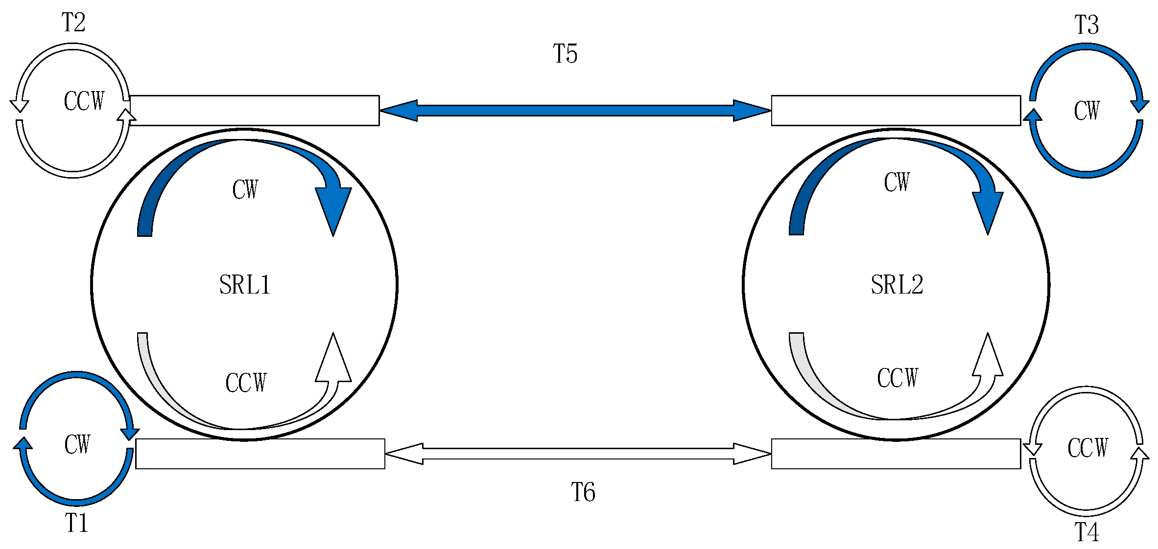
2.1. Theoretical Model

The schematic diagram of the synchronization system for mutually injected semiconductor ring lasers (MISRLs) is illustrated in Figure 1. In this system, the clockwise (CW) and counter-clockwise (CCW) modes emitted by two SRLs are mutually injected into each other through two distinct channels, with injection delay times of T5 and T6, respectively. In addition, each SRL’s output modes receive optical feedback from their respective counter-propagating modes, with feedback delay times of T1, T2, T3, and T4. By incorporating the optical feedback and injection terms into the SRL rate equations, the equations for the MISRLs synchronization system can be expressed as follows [27,28]:
d E 1 C W d t = κ ( 1 + i α ) g 1 C W N 1 1 E 1 C W ( k d + i k c ) E 1 C C W + k 2 E 1 C C W ( t T 2 ) e i ω T 2                         + σ 2 E 2 C W ( t T 6 ) e i 2 π f t + F 1
d E 1 C C W d t = κ ( 1 + i α ) g 1 C C W N 1 1 E 1 C C W ( k d + i k c ) E 1 C W + k 1 E 1 C W ( t T 1 ) e i ω T 1                             + σ 1 E 2 C C W ( t T 5 ) e i 2 π f t + F 1
d E 2 C W d t = κ ( 1 + i α ) g 2 C W N 2 1 E 2 C W ( k d + i k c ) E 2 C C W + k 4 E 2 C C W ( t T 4 ) e i ω T 4                             + σ 1 E 1 C W ( t T 5 ) e i 2 π f t + F 2
d E 2 C C W d t = κ ( 1 + i α ) g 2 C C W N 2 1 E 2 C C W ( k d + i k c ) E 2 C W + k 3 E 2 C W ( t T 3 ) e i ω T 3                             + σ 2 E 1 C C W ( t T 6 ) e i 2 π f t + F 2
d N 1 , 2 d t = γ μ N 1 , 2 g 1 , 2 C W N 1 , 2 E 1 , 2 C W 2 g 1 , 2 C C W N 1 , 2 E 1 , 2 C C W 2
g 1 , 2 C C W = 1 s E 1 , 2 C C W 2 c E 1 , 2 C W 2
g 1 , 2 C W = 1 s E 1 , 2 C W 2 c E 1 , 2 C C W 2
F 1 , 2 = β τ p N 1 , 2 ζ 1 , 2 t
ζ i t = 0
ζ i t ζ j t ' = 2 δ i j δ t t '
where E is the mean-field slowly varying complex amplitudes of the electric field, N is the carrier number, and g1,2 represent the gain. Subscript 1 and 2 stand for SRL1 and SRL2, and subscripts CW and CCW stand for the CW and CCW modes, respectively. σ is the injection coefficient, k is the feedback coefficient, T5 and T6 are the injection delays of the upper and lower channels, and T1, T2, T3, and T4 are the feedback delays of the CW mode and CCW mode of SRL1 and SRL2, respectively. Δf is the frequency detuning between two SRLs. F represents the noise, and ζ1,2 are two independent complex Gaussian random numbers [29]. The physical meanings and values of the other parameters are shown in Table 1.
This work will use the cross-correlation (CC) function to measure the time delay characteristics of the generated chaotic signal. The mathematical definition of the CC function is as follows:
C C ( Δ t ) = x 1 ( t ) x 1 ( t ) x s 2 ( t ) x s 2 ( t ) x 1 ( t ) x 1 ( t ) 2 x s 2 ( t ) x s 2 ( t ) 2
Among them, x(t) is the time series, Δt is the time delay, and represents the time average. xs(t) = x (t + Δt) is the value of the time series after the time shift Δt, and the range of absolute values of the CC number is [0, 1], where 0 indicates complete independence and 1 indicates complete correlation.

2.2. Synchronization Analysis

According to the chaos synchronization theory [4], synchronization can be divided into ‘generalized’ synchronization and ‘complete’ synchronization. Generalized synchronization is achieved through the nonlinear amplification effect of the laser under a high injection intensity, and the synchronization performance is determined by the injection-locking effect. Complete synchronization occurs when the receiver replicates the output of the transmitting laser. This work considers the case of a complete synchronization situation, where the injection and feedback parameters satisfy symmetry and can achieve synchronization. Due to the fact that the SRL have two output modes CW and CCW, there will be two situations where injection and feedback are equal, and cross-equal. Considering the two synchronization situations of isochronal synchronization and leader-laggard synchronization, four synchronization states will appear, namely, isochronal chaos synchronization between the same modes (ICSS), leader-laggard chaos synchronization for the same modes (LLCSS), isochronal chaos synchronization between different modes (ICSD), leader-laggard chaos synchronization between different modes (LLCSD).
Based on the principle of the symmetrical theory [30], when SRL1 and SRL2 are synchronized, the following relationship must be satisfied:
E 1 ( t ) = E 2 ( t + Δ t )
N 1 ( t ) = N 2 ( t + Δ t )
Here, Δt represents the synchronization time delay between SRL1 and SRL2. When the output of SRL1 drives SRL2, Δt > 0. When the outputs of SRL1 and SRL2 are isochronal-synchronized, Δt = 0. When the output of SRL1 lags behind that of SRL2, Δt < 0. Since each SRL emits two modes of signals, four distinct synchronization types are assumed, and a theoretical analysis is conducted to explore their characteristics.

2.2.1. Chaos Synchronization Between the Same Modes

When SRL1 and SRL2 are synchronized with same modes, the CW mode and CCW mode are equal:
E 1 C W ( t ) = E 2 C W ( t + Δ t )
E 1 C C W ( t ) = E 2 C C W ( t + Δ t )
By substituting the complex electric field Equations (1)–(5) into the above equations, the following relationships can be obtained:
k 2 E 1 C C W ( t T 2 ) + σ 2 E 2 C W ( t T 6 ) = k 4 E 2 C C W ( t + Δ t T 4 ) + σ 1 E 1 C W ( t + Δ t T 5 )
k 1 E 1 C W ( t T 1 ) + σ 1 E 2 C C W ( t T 5 ) = k 3 E 2 C W ( t + Δ t T 3 ) + σ 2 E 1 C C W ( t + Δ t T 6 )
Considering the case of ICSS, the feedback and injection are equal to each other:
k 2 E 1 C C W ( t T 2 ) = k 4 E 2 C C W ( t + Δ t T 4 )
σ 2 E 2 C W ( t T 6 ) = σ 1 E 1 C W ( t + Δ t T 5 )
k 1 E 1 C W ( t T 1 ) = k 3 E 2 C W ( t + Δ t T 3 )
σ 1 E 2 C C W ( t T 5 ) = σ 2 E 1 C C W ( t + Δ t T 6 )
Substitute (15) and (16) into the above equation:
k 2 E 2 C C W ( t + Δ t T 2 ) = k 4 E 2 C C W ( t + Δ t T 4 )
σ 2 E 2 C W ( t T 6 ) = σ 1 E 2 C W ( t + 2 Δ t T 5 )
k 1 E 2 C W ( t + Δ t T 1 ) = k 3 E 2 C W ( t + Δ t T 3 )
σ 1 E 2 C C W ( t T 5 ) = σ 2 E 2 C C W ( t + 2 Δ t T 6 )
The parameters must satisfy the following:
k 1 = k 3 ,   k 2 = k 4 ,   σ 1 = σ 2 ,   T 1 = T 3 ,   T 2 = T 4 ,   T 5 = T 6
Meanwhile, the synchronization time delay between SRL1 and SRL2 is as follows:
Δ t = 0
The above analysis shows that, when the injection coefficients and injection time delay of the two channels are equal, and the feedback time delay and feedback coefficient of the same mode are the same, the system can achieve ICSS.
In addition, there are also cases of LLCSS:
k 2 E 1 C C W ( t T 2 ) = σ 1 E 1 C W ( t + Δ t T 5 )
σ 2 E 2 C W ( t T 6 ) = k 4 E 2 C C W ( t + Δ t T 4 )
k 1 E 1 C W ( t T 1 ) = σ 2 E 1 C C W ( t + Δ t T 6 )
σ 1 E 2 C C W ( t T 5 ) = k 3 E 2 C W ( t + Δ t T 3 )
The above relationship requires the following:
E 1 C C W ( t ) = E 1 C W ( t + Δ t ) E 2 C W ( t ) = E 2 C C W ( t + Δ t ) E 1 C C W ( t ) = E 1 C W ( t + Δ t ) E 2 C W ( t ) = E 2 C C W ( t + Δ t )
It can be seen that the case for LLCSD does not exist; this is because, in the case of leader-laggard synchronization, the time-series output from SRL2 must be later than SRL1 (Δt ≠ 0). However, the condition for Equation (33) to hold must satisfy Δt = 0, so the relationship of leader-laggard synchronization for the same mode does not satisfy.

2.2.2. Synchronization Between the Different Modes

When synchronizing with different modes, the CW and CCW modes of SRL1 and SRL2 cross equally:
E 1 C W ( t ) = E 2 C C W ( t + Δ t )
E 1 C C W ( t ) = E 2 C W ( t + Δ t )
Substituting the complex electric field relationship of SRL into the above equation, the conditions for SRL1 and SRL2 synchronization can be obtained as follows:
k 2 E 1 C C W ( t T 2 ) + σ 2 E 2 C W ( t T 6 ) = k 3 E 2 C W ( t + Δ t T 3 ) + σ 2 E 1 C C W ( t + Δ t T 6 )
k 1 E 1 C W ( t T 1 ) + σ 1 E 2 C C W ( t T 5 ) = k 4 E 2 C C W ( t + Δ t T 4 ) + σ 1 E 1 C W ( t + Δ t T 5 )
This condition can be further decomposed into two situations. Consider the case of ICSD:
k 2 E 1 C C W ( t T 2 ) = k 3 E 2 C W ( t + Δ t T 3 )
k 1 E 1 C W ( t T 1 ) = k 4 E 2 C C W ( t + Δ t T 4 )
Substitute (34) and (35) into the above equation to obtain the following:
k 2 E 2 C W ( t + Δ t T 2 ) = k 3 E 2 C W ( t + Δ t T 3 )
k 1 E 2 C C W ( t + Δ t T 1 ) = k 4 E 2 C C W ( t + Δ t T 4 )
The synchronization conditions for ICSD are as follows:
k 1 = k 4 ,   k 2 = k 3 ,   T 1 = T 4 ,   T 2 = T 3
The synchronization delay between the two lasers is as follows:
Δ t = 0
The above analysis indicates that ICSD can be achieved when the feedback coefficient and feedback delay of the cross-mode of two lasers are equal.
Further, consider the situation of LLCSD:
k 2 E 1 C C W ( t T 2 ) = σ 2 E 1 C C W ( t + Δ t T 6 )
σ 2 E 2 C W ( t T 6 ) = k 3 E 2 C W ( t + Δ t T 3 )
k 1 E 1 C W ( t T 1 ) = σ 1 E 1 C W ( t + Δ t T 5 )
σ 1 E 2 C C W ( t T 5 ) = k 4 E 2 C C W ( t + Δ t T 4 )
Simplify the above equation and obtain the following:
t T 2 = t + Δ t T 6
t T 6 = t + Δ t T 3
t T 1 = t + Δ t T 5
t T 5 = t + Δ t T 4
The synchronization conditions for LLCSD are as follows:
k 1 = k 4 = σ 1 k 2 = k 3 = σ 2 Δ t = T 3 T 6 = T 6 T 2 = T 4 T 5 = T 5 T 1 = 1 2 T 3 T 2 = 1 2 T 4 T 1 T 3 + T 2 = 2 T 6 T 1 + T 4 = 2 T 5
The above analysis indicates that, when the feedback coefficients of the cross-modes are equal and the sum of feedback time delays is twice the injection delay time, the system can achieve LLCSD. The synchronization delay time is determined by the feedback delay time between the cross-modes. Next, we will study the performance of these three synchronization modes.

3. Results and Discussion

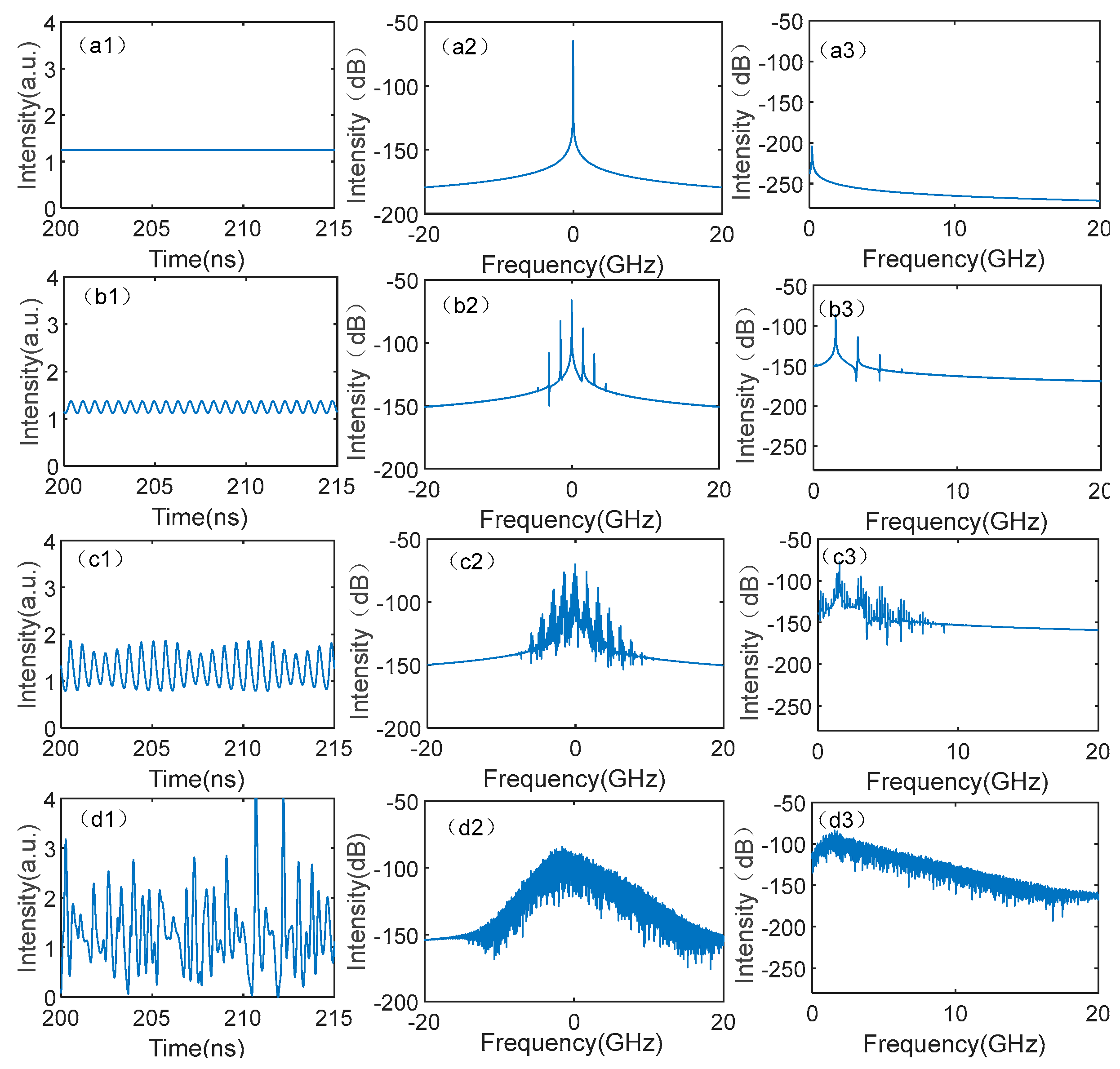
3.1. Dynamics Evolution of SRL

Since the chaotic synchronization system is established on the chaotic state of SRL, the dynamic evolution of a single SRL under external optical feedback is first studied. To simplify the analysis, the feedback coefficients of the CW and CCW modes are set to the same. The output of the two modes is the same due to the symmetry, so only the dynamic evolution of the CW mode is given in Figure 2. For k1 = k2 = 0.5 ns−1, as shown in Figure 2a1, the time series exhibits a steady state, with no strong frequency components in the optical spectrum (Figure 2a2) and power spectrum (Figure 2a3). In this situation, the SRL operates in a steady state. For k1 = k2 = 0.71 ns−1, as shown in Figure 2b, regular oscillations are shown in the time series, and the optical spectrum shows an equidistant frequency distribution. The power spectrum has a strong frequency component followed by higher harmonics. At this time, the SRL exhibits a period-1 oscillation. For k1 = k2 = 0.9 ns−1, as shown in Figure 2c, multiple frequency components are added near the peak frequency in the power spectrum. At this time, the SRL operates in a multi-period state. For k1 = k2 = 5 ns−1, as shown in Figure 2d, the time series exhibits irregular oscillations, and the optical spectra and power spectra show broadening without prominent peaks, indicating that the SRL operates in a chaotic state under coherence collapse. The emergence of chaos is due to the fact that the SRLs are a high-dimensional nonlinear system that is sensitive to external optical perturbations. When the laser is subject to external optical injection, their emission frequency and gain spectrum peak are detuned, resulting in anomalous dispersion effects at the lasing frequency. When the intensity of external perturbations is appropriate, chaos occurs. The above analysis shows that the SRL undergoes a dynamic evolution process of period-doubling bifurcation to chaos, which is a standard evolution process for SLs to enter the chaotic state.

3.2. Synchronization Performance Analysis of Three Synchronization Modes

According to the theoretical analysis of synchronization, it is found that there are three synchronization modes. Next, we will study the synchronization performance of these synchronization modes.

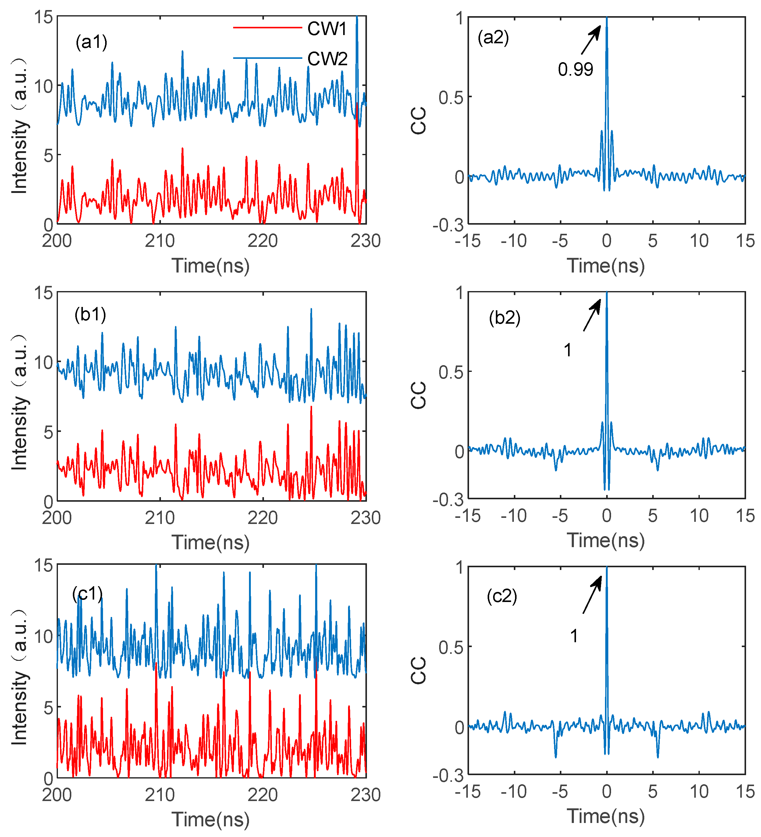
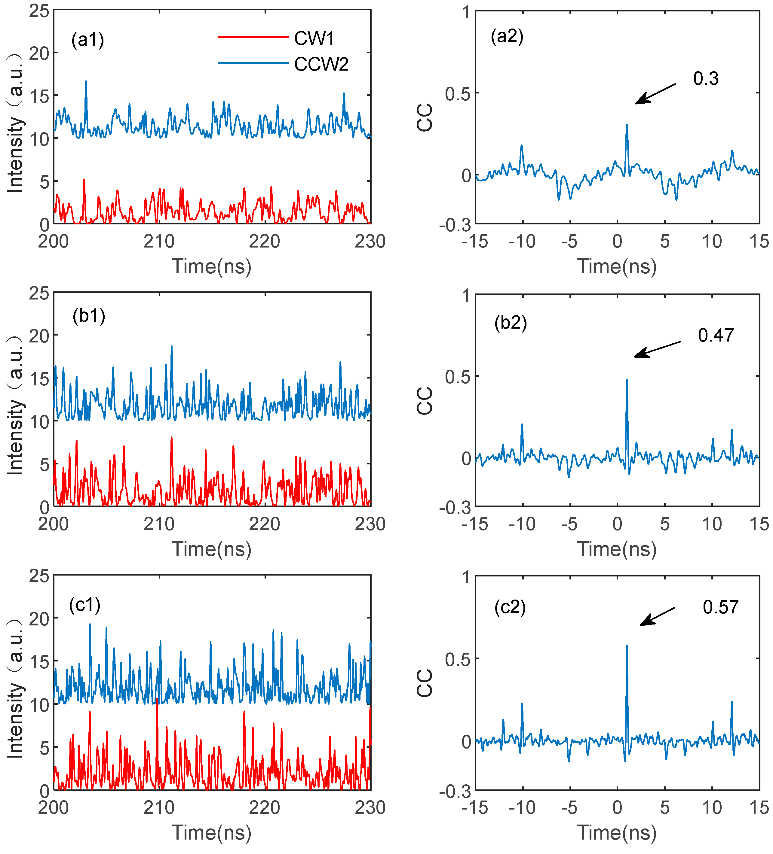
3.2.1. Isochronal Chaos Synchronization Between the Same Modes (ICSS)

Figure 3 shows the synchronization situation of ICSS, due to a large number of parameters; to simplify the discussion, the injection and feedback parameters are fixed at T1 = T3 = T5 = T6 = 5 ns, T2 = T4 = 5.3 ns, and σ1 = σ2 = k1 = k3 = 2 ns−1. Under this condition, the outputs of the two lasers are the same. Therefore, only the synchronization diagram of the CW mode is provided below. As shown in Figure 3a1, the chaotic time series output by CW1 and CW2 are almost identical under k2 = k4 = 5 ns−1. For ease of observation, the time series of CW2 is shifted upward by five units as a whole. In order to quantify the synchronization quality, Figure 3a2 shows the CC of the time series of CW1 and CW2, where the maximum cross-correlation coefficient (MCCC) reaches 0.99, indicating that the two SRLs have been completely synchronized. Moreover, in Figure 3a2, the MCCC is located around 0 ns, which indicates that the two SRLs achieve isochronal synchronization. With the increase in k2 and k4 to 10 ns−1 and 15 ns−1, as shown in Figure 3b,c, the time-series waveforms of CW1 and CW2 are also highly consistent, and the MCCC value is near 1, indicating high-quality synchronization between the two SRLs. Therefore, it can be seen that the feedback coefficient will not affect the synchronization quality in the ICSS.

3.2.2. Isochronal Chaos Synchronization Between Different Modes (ICSD)

Figure 4 shows the synchronization situation of ICSD, with the parameters fixed at T1 = T3 = T5 = T6 = 5 ns, T2 = T4 = 5.3 ns, and σ1 = k1 = k4 = 5 ns−1. Under these parameters, the outputs of CW1 (CCW1) and CCW2 (CW2) are the same, respectively. Therefore, only the synchronization diagram of the CW1 and CCW2 outputs is provided. For k2 = k3 = σ2 = 5 ns−1, as shown in Figure 4a1, the time series of CW1 and CCW2 are not exactly the same. Combined with the CC diagram in Figure 4a2, the MCCC of 0.66 appears at t = 0 ns, indicating that the two SRLs show incomplete isochronal synchronization. For k2 = k3 = σ2 at 10 and 15 ns−1, respectively, as shown in Figure 4b,c, the time-series waveforms of CW1 and CW2 are not highly consistent, and the CC diagrams indicate that the MCCC reaches 0.69 and 0.87, indicating that it still shows incomplete synchronization at this time. By combining the CC diagrams of Figure 4a2,b2,c2, it can be observed that, unlike ICSS, the time delay signature (TDS) can be obviously observed at ±5 ns and ±10 ns for ICSD.

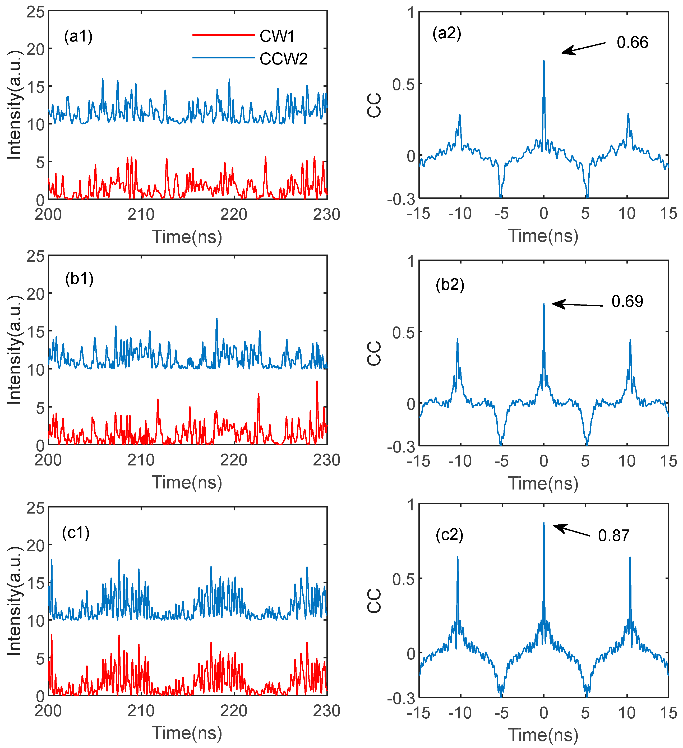
3.2.3. Leader-Laggard Chaos Synchronization Between Different Modes (LLCSD)

Figure 5 shows the synchronization situation of LLCSD, with the parameters fixed at T1 = 5 ns, T2 = 4 ns, T3 = 6 ns, T4 = 7 ns, T5 = 6 ns, T6 = 5 ns, and σ1 = k1 = k4 = 5 ns−1. According to the theoretical analysis, under this parameter condition, the outputs of CW1 (CCW1) and CCW2 (CW2) are the same, respectively. Similar to ICSD, only the CW1 and CCW2 are presented below. For k2 = k3 = σ2 = 5 ns−1, as shown in Figure 5a1, in order to facilitate a comparison, we shift the time series of CCW2 to the left by 1 ns and find there is no similarity between the waveforms of CW1 and CCW2. Figure 5a2 shows the CC diagrams of CW1 and CCW2, with an MCCC of 0.3 at t = 1 ns, indicating that the two SRLs are incomplete-leader-laggard-synchronized. As shown in Figure 5b, for k2 = k3 = σ2 = 10 ns−1, the MCCC approaches 0.47, and the similarity of the time-series waveform is improved. As shown in Figure 5c, for k2 = k3 = σ2 = 15 ns−1, the MCCC approaches 0.6, and the similarity of the time-series waveform is also improved, indicating that the increase in feedback and injection coefficients improved the synchronization quality of the two SRLs. Compared with ICSD, LLCSD‘s TDS is not obvious but also can be observed at ±5 ns, ±10 ns, and ±12 ns.
For the chaos-based secure communication system, the existence of the time TDS can affect the system security [31]. The eavesdropper can use TDS and neural network computation to reconstruct chaotic signals, posing a significant threat to the security of the system [32]. Many effective schemes are proposed to suppress the TDS in SL, such as chirped FBG feedback [33], variable polarization optical injection [34], scattering feedback and optical injection [35], delayed self-interference [36], cross-feedback [31], cross-mutual injection [37], controlling the linewidth enhancement factor [38], and so on.
Next, the effects of the feedback and injection coefficient on the TDS of the three synchronization modes are studied. The results are shown in Figure 6. It can be observed in Figure 6a1 that, in ICSS, with the increase in the feedback coefficient, the TDS decreases to 0.06 and then gradually increases. It can be seen from Figure 6b1 that the TDS of ICSD first increases and then slowly decreases with the increase in the injection and feedback coefficient. As shown in Figure 6c1, the variation trend of LLCSD is similar to ICSS, but the minimum value of TDS is larger than ICSS. The right of Figure 6 shows the MCCC varying with the feedback and injection coefficient. In Figure 6a2, ICSS has the best synchronization quality under all parameters. It can be observed in Figure 6b2 that, within a specific parameter range, the synchronization quality of ICSD is kept at a low level. Figure 6c2 shows that the synchronization quality of LLCSD will change dramatically with feedback and injection coefficients.
Figure 7 shows the two-dimensional maps of the feedback and injection coefficient to further study the synchronization quality of the three types of chaos synchronization modes. As shown in Figure 7a, for ICSS, high-quality chaos synchronization can be achieved under almost all parameters, which means that ICSS is insensitive to parameter changes. Figure 7b shows that, in the case of ICSD, the MCCC is low when the feedback and injection coefficients are low. With the increase in the feedback and injection coefficient, the MCCC is increased. This is because a low feedback and injection strength can quickly aggravate the system asymmetry caused by different initial conditions of the mutual injection system. Figure 7c shows that, for LLCSD, high quality chaos synchronization only occurs with large feedback and injection coefficients. The above results differ from the existing research results of traditional SLs, and this may be due to the structural differences between the SRLs and the traditional SL [39,40]. Therefore, all three synchronization structures can achieve high-quality chaos synchronization. Among them, ICSS can achieve high-quality synchronization under various parameters, while ICSD and LLCSD require higher injection and feedback parameters to achieve high-quality synchronization.

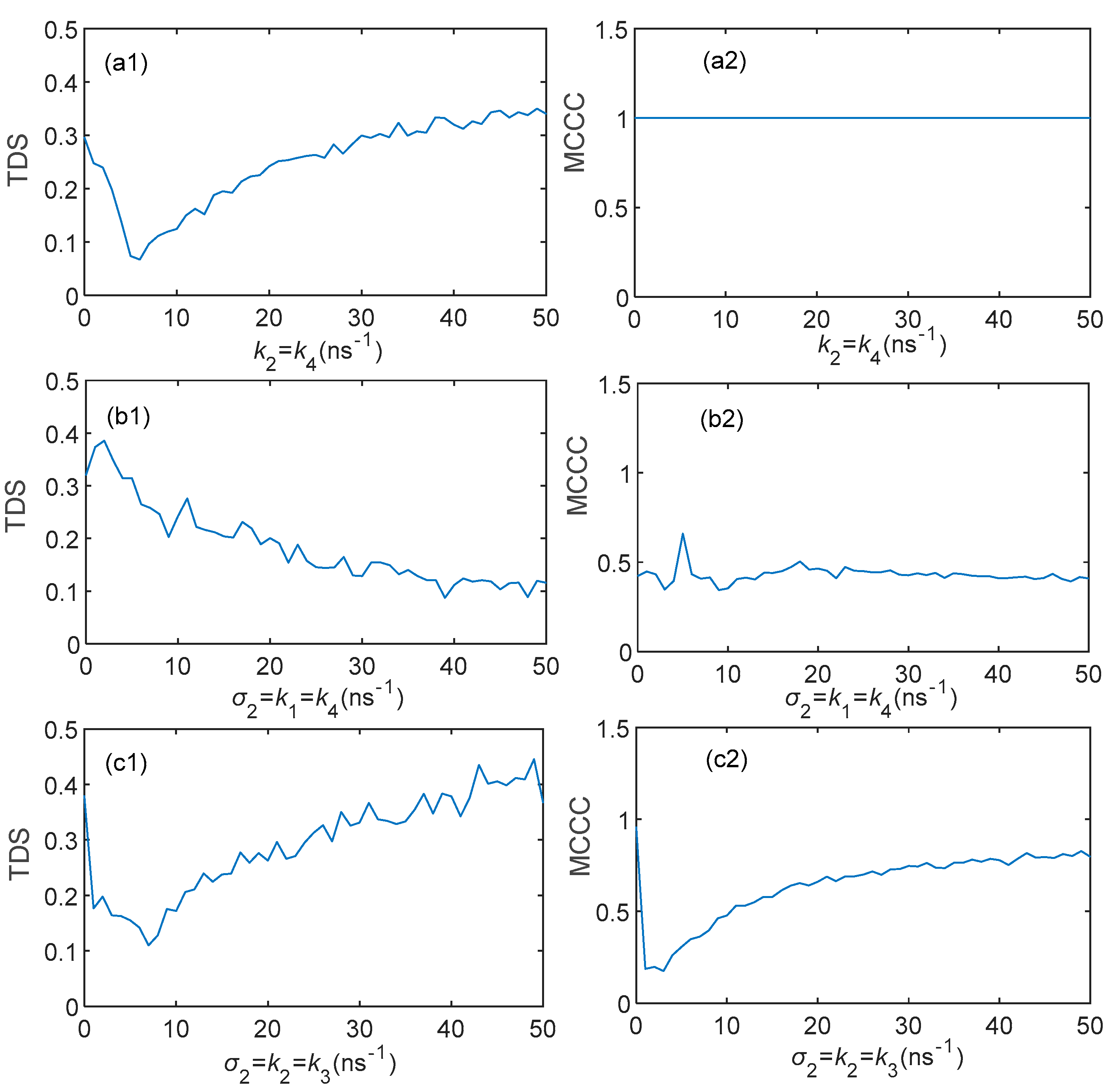
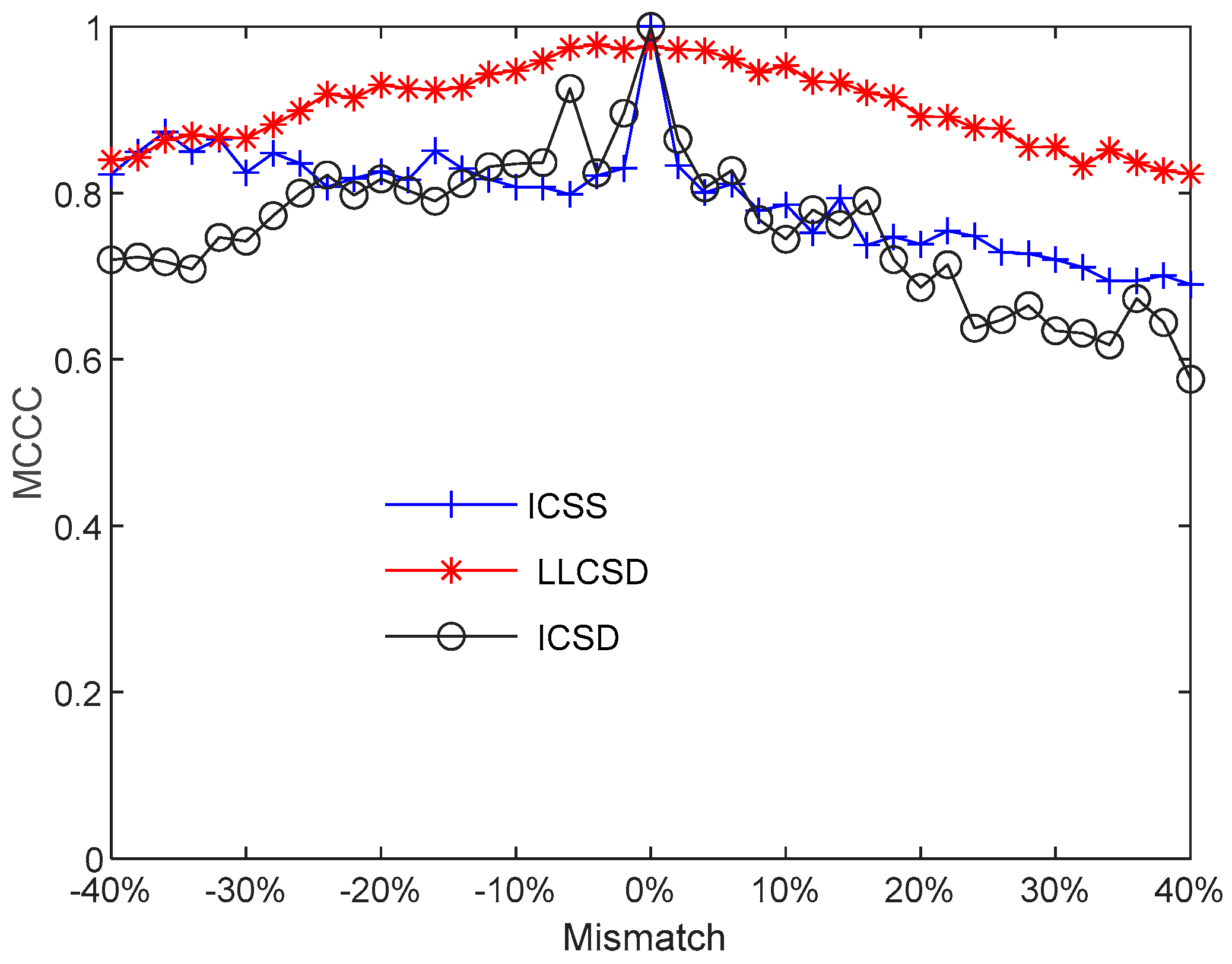
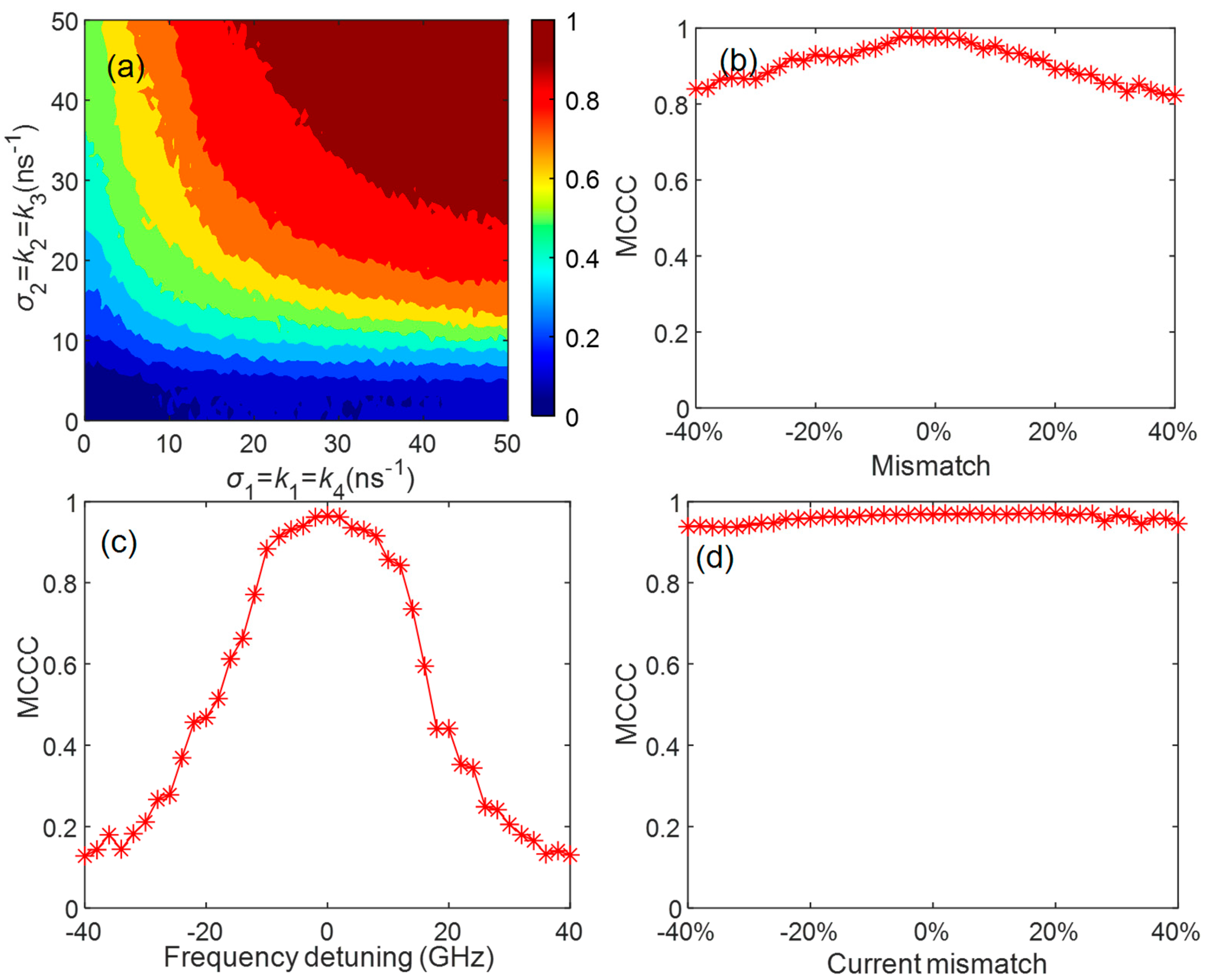
3.3. Effect of Parameter Mismatch on Three Chaos Synchronization Modes

From the above theoretical analysis and simulation verification, it can be found that the chaos synchronization modes can be switched by changing the feedback and injection coefficients to adapt to different application scenarios. There is the fact that the SRL system may have a slight mismatch of the intrinsic parameters caused by the limitation of the manufacturing technology in the practical application of chaos secure communication, and the chaotic signal has the characteristic of being sensitive to initial conditions; the decline in synchronization quality will lead to the obstruction of secure communication, which requires our system to have a certain tolerance for parameter mismatch. Here, the parameter mismatch of three synchronous modes of SRLs is compared and analyzed, and the processing methods are referenced from the paper [41]; fix the parameters of SRL1, and increase the ĸ, α, and g parameters and decrease the γ, kd, and kc parameters by the same amount in SRL2. The three broken lines in Figure 8 correspond to the effect of the parameter mismatch of ICSS, ICSD, and LLCSD on the MCCC. When the MCCC is more than 0.9, it can be regarded as high-quality synchronization. It can be seen in the figure that the robustness of LLCSD to a parameter mismatch is higher than that of ICSS and ICSD. The robustness range of the LLCSD parameter mismatch is [−25%, 20%]. Therefore, it can be concluded that the stability of leader-laggard synchronization is significantly better than isochronal synchronization.
Then, the influences of the frequency detuning and current mismatch on the synchronization performance are discussed. As shown in Figure 9a, the three kinds of chaotic synchronization modes are very sensitive to frequency detuning, and ICSS and ICSD are more significant than LLCSD. For LLCSD, when the frequency detuning is within the range of [−10, +10] GHz, the MCCC remains above 0.9. For ICSS and ICSD, frequency detuning quickly reduces the MCCC to below 0.6. As shown in Figure 9b, for LLCSD, high-quality synchronization can be maintained within the range of [−40%, 40%] for the current mismatch. For ICSS, the current mismatch will cause the MCCC to drop to around 0.85; for ICSD, the MCCC will constantly decrease with the increase in the current mismatch. Therefore, LLCSD has a significantly better stability than ICSS and ICSD for frequency detuning and current mismatch.

3.4. The Impact of Noise on the Synchronization Performance of LLCSD

Finally, the impact of the noise on the synchronization performance of LLCSD is discussed [29]. As shown in Figure 10a, compared to Figure 7c, the high-quality synchronization area has been reduced, indicating that the noise has lowered the synchronization quality. Nevertheless, high-quality synchronization can still be maintained under larger injection and feedback parameters. As shown in Figure 10b–d, compared to the case without noise, LLCSD still has a high robustness to parameter mismatch after introducing noise.

4. Conclusions

This paper investigates the synchronization performance of the chaos synchronization secure communication system constructed by mutual injection SRLs. Firstly, the dynamic evolution of SRLs under external perturbation is studied, and it is found that, by changing the feedback strength, SRLs present stability, periodic oscillation, and chaotic oscillation. Secondly, a theoretical analysis was conducted on the nonlinear dynamic equations of the mutual injection SRL synchronization system, and it was found that there are three synchronization modes: ICSS, ICSD, and LLCSD. Then, the synchronization performance of the three types of synchronization modes was studied, and the results indicate that the ICSS can realize chaos synchronization with a low TDS easily and has the broadest range of high-quality chaotic synchronization parameters and good security, while LLCSD demonstrates strong stability—the best robustness to the mismatch of parameters, frequency detuning, and current mismatch. In addition, the impact of noise on the synchronization performance is discussed, and we found that the LLCSD still has a good robustness against parameter mismatch. Under large feedback and injection parameters, LLSCD is identified as the optimal synchronization structure. These findings provide valuable theoretical insights for the application of SRLs in chaotic secure communication.

Author Contributions

Conceptualization, Z.J. and D.Z.; methodology Z.J.; software, R.T. and Z.J.; validation, R.T., D.Z. and J.W.; formal analysis, Z.J.; investigation, R.T. and D.Z.; resources, Z.J.; data curation, R.T.; writing—original draft preparation, R.T.; writing—review and editing, Z.J.; visualization, R.T. and J.W.; supervision, R.T.; project administration, Z.J.; funding acquisition, Z.J. All authors have read and agreed to the published version of the manuscript.

Funding

This research was funded by the Natural Science Foundation of Hubei Province (No. 2022CFB527) and Natural Science Foundation of Chongqing City (No. CSTC2021jcyj-msxmX0531); and the Scientific Research Projects of Jingchu University of Technology (Nos. YY202207, YB202212, and QN202312).

Institutional Review Board Statement

Not applicable.

Informed Consent Statement

Not applicable.

Data Availability Statement

Data underlying the results presented in this paper are not publicly available at this time but may be obtained from the authors upon reasonable request.

Conflicts of Interest

The authors declare no conflicts of interest.

Abbreviations

The following abbreviations are used in this manuscript:
MISRLsMutually injected semiconductor ring lasers
SRLsSemiconductor ring lasers
SLsSemiconductor lasers
CCWCounter-clockwise
CWClockwise
ICSSIsochronal chaos synchronization between the same modes
ICSDIsochronal chaos synchronization between different modes
LLCSDLeader-laggard chaos synchronization between different modes
CCCross-correlation
MCCCMaximum cross-correlation coefficient

References

  1. Pecora, L.M.; Carroll, T.L. Synchronization in Chaotic Systems. Phys. Rev. Lett. 1990, 64, 821–824. [Google Scholar] [CrossRef]
  2. Soriano, M.C.; García-Ojalvo, J.; Mirasso, C.R.; Fischer, I. Complex Photonics: Dynamics and Applications of Delay-Coupled Semiconductors Lasers. Rev. Mod. Phys. 2013, 85, 421–470. [Google Scholar] [CrossRef]
  3. Ke, J.; Yi, L.; Xia, G.; Hu, W. Chaotic Optical Communications over 100-Km Fiber Transmission at 30-Gb/s Bit Rate. Opt. Lett. 2018, 43, 1323. [Google Scholar] [CrossRef] [PubMed]
  4. Sciamanna, M.; Shore, K.A. Physics and Applications of Laser Diode Chaos. Nat. Photonics 2015, 9, 151–162. [Google Scholar] [CrossRef]
  5. Donati, S.; Horng, R.-H. The Diagram of Feedback Regimes Revisited. IEEE J. Sel. Top. Quantum Electron. 2013, 19, 1500309. [Google Scholar] [CrossRef]
  6. Kelleher, B.; Wishon, M.J.; Locquet, A.; Goulding, D.; Tykalewicz, B.; Huyet, G.; Viktorov, E.A. Delay Induced High Order Locking Effects in Semiconductor Lasers. Chaos Interdiscip. J. Nonlinear Sci. 2017, 27, 114325. [Google Scholar] [CrossRef]
  7. Fischer, A.P.A.; Andersen, O.K.; Yousefi, M.; Stolte, S.; Lenstra, D. Experimental and Theoretical Study of Filtered Optical Feedback in a Semiconductor Laser. IEEE J. Quantum Electron. 2000, 36, 375–384. [Google Scholar] [CrossRef]
  8. Fischer, A.P.A.; Yousefi, M.; Lenstra, D.; Carter, M.W.; Vemuri, G. Experimental and Theoretical Study of Semiconductor Laser Dynamics Due to Filtered Optical Feedback. IEEE J. Sel. Top. Quantum Electron. 2004, 10, 944–954. [Google Scholar] [CrossRef]
  9. Naumenko, A.; Besnard, P.; Loiko, N.; Ughetto, G.; Bertreux, J.C. Characteristics of a Semiconductor Laser Coupled with a Fiber Bragg Grating with Arbitrary Amount of Feedback. IEEE J. Quantum Electron. 2003, 39, 1216–1228. [Google Scholar] [CrossRef]
  10. Argyris, A.; Syvridis, D.; Larger, L.; Annovazzi-Lodi, V.; Colet, P.; Fischer, I.; García-Ojalvo, J.; Mirasso, C.R.; Pesquera, L.; Shore, K.A. Chaos-Based Communications at High Bit Rates Using Commercial Fibre-Optic Links. Nature 2005, 438, 343–346. [Google Scholar] [CrossRef]
  11. Ke, J.; Yi, L.; Yang, Z.; Yang, Y.; Zhuge, Q.; Chen, Y.; Hu, W. 32 Gb/s Chaotic Optical Communications by Deep-Learning-Based Chaos Synchronization. Opt. Lett. 2019, 44, 5776–5779. [Google Scholar] [CrossRef] [PubMed]
  12. Zhao, A.; Jiang, N.; Liu, S.; Zhang, Y.; Qiu, K. Generation of Synchronized Wideband Complex Signals and Its Application in Secure Optical Communication. Opt. Express 2020, 28, 23363–23373. [Google Scholar] [CrossRef] [PubMed]
  13. Zhong, D.; Yang, H.; Xi, J.; Zeng, N.; Xu, Z. Exploring New Chaotic Synchronization Properties in the Master-Slave Configuration Based on Three Laterally Coupled Semiconductor Lasers with Self-Feedback. Opt. Express 2020, 28, 25778–25794. [Google Scholar] [CrossRef] [PubMed]
  14. Wang, Z.; Li, P.; Jia, Z.; Wang, W.; Xu, B.; Shore, K.A.; Wang, Y. Synchronization of Polarization Chaos in Mutually Coupled Free-Running VCSELs. Opt. Express 2021, 29, 17940–17950. [Google Scholar] [CrossRef]
  15. Liu, S.; Jiang, N.; Zhang, Y.; Wang, C.; Zhao, A.; Qiu, K.; Zhang, Q. Secure Key Distribution Based on Hybrid Chaos Synchronization between Semiconductor Lasers Subject to Dual Injections. Opt. Express 2022, 30, 32366–32380. [Google Scholar] [CrossRef]
  16. Chlouverakis, K.E.; Mikroulis, S.; Stamataki, I.; Syvridis, D. Chaotic Dynamics of Semiconductor Microring Lasers. Opt. Lett. 2007, 32, 2912–2914. [Google Scholar] [CrossRef]
  17. Ermakov, I.V.; Van Der Sande, G.; Danckaert, J. Semiconductor Ring Laser Subject to Delayed Optical Feedback: Bifurcations and Stability. Commun. Nonlinear Sci. Numer. Simul. 2012, 17, 4767–4779. [Google Scholar] [CrossRef]
  18. Takougang Kingni, S.; Van Der Sande, G.; Gelens, L.; Erneux, T.; Danckaert, J. Direct Modulation of Semiconductor Ring Lasers: Numerical and Asymptotic Analysis. J. Opt. Soc. Am. B 2012, 29, 1983–1992. [Google Scholar] [CrossRef]
  19. Meng, B.; Singleton, M.; Hillbrand, J.; Franckié, M.; Beck, M.; Faist, J. Dissipative Kerr Solitons in Semiconductor Ring Lasers. Nat. Photonics 2022, 16, 142–147. [Google Scholar] [CrossRef]
  20. Mu, P.; Wang, K.; Liu, G.; Wang, Y.; Liu, X.; Guo, G.; Hu, G. Spike Dynamics Analysis in Semiconductor Ring Laser. Electronics 2024, 13, 260. [Google Scholar] [CrossRef]
  21. Mashal, L.; Nguimdo, R.M.; Van Der Sande, G.; Soriano, M.C.; Danckaert, J.; Verschaffelt, G. Low-Frequency Fluctuations in Semiconductor Ring Lasers with Optical Feedback. IEEE J. Quantum Electron. 2013, 49, 790–797. [Google Scholar] [CrossRef]
  22. Kacmoli, S.; Sivco, D.L.; Gmachl, C.F. Unidirectional Mode Selection in Bistable Quantum Cascade Ring Lasers. Opt. Express 2022, 30, 47475–47484. [Google Scholar] [CrossRef] [PubMed]
  23. Li, N.; Pan, W.; Xiang, S.; Luo, B.; Yan, L.; Zou, X. Hybrid Chaos-Based Communication System Consisting of Three Chaotic Semiconductor Ring Lasers. Appl. Opt. 2013, 52, 1523–1530. [Google Scholar] [CrossRef] [PubMed]
  24. Li, N.; Pan, W.; Yan, L.; Luo, B.; Zou, X. Enhanced Chaos Synchronization and Communication in Cascade-Coupled Semiconductor Ring Lasers. Commun. Nonlinear Sci. Numer. Simul. 2014, 19, 1874–1883. [Google Scholar] [CrossRef]
  25. Li, J.; Xiang, S.; Wang, H.; Gong, J.; Wen, A. A Novel Image Encryption Algorithm Based on Synchronized Random Bit Generated in Cascade-Coupled Chaotic Semiconductor Ring Lasers. Opt. Lasers Eng. 2018, 102, 170–180. [Google Scholar] [CrossRef]
  26. Yuan, G.; Zhang, X.; Wang, Z. Generation and Synchronization of Feedback-Induced Chaos in Semiconductor Ring Lasers by Injection-Locking. Optik 2014, 125, 1950–1953. [Google Scholar] [CrossRef]
  27. Sorel, M.; Giuliani, G.; Scire, A.; Miglierina, R.; Donati, S.; Laybourn, P.J.R. Operating Regimes of Gaas-Algaas Semiconductor Ring Lasers: Experiment and Model. IEEE J. Quantum Electron. 2003, 39, 1187–1195. [Google Scholar] [CrossRef]
  28. Ermakov, I.V.; Kingni, S.T.; Tronciu, V.Z.; Danckaert, J. Chaotic Semiconductor Ring Lasers Subject to Optical Feedback: Applications to Chaos-Based Communications. Opt. Commun. 2013, 286, 265–272. [Google Scholar] [CrossRef]
  29. Scire, A.; Perez, A.; Perez, T.; Van Der Sande, G.; Colet, P.; Mirasso, C.R.; Balle, S. Bistability and All-Optical Switching in Semiconductor Ring Lasers. In Proceedings of the 2007 9th International Conference on Transparent Optical Networks, Rome, Italy, 1–5 July 2007; IEEE: Rome, Italy, 2007; pp. 21–24. [Google Scholar]
  30. Chiang, M.C.; Chen, H.-F.; Liu, J.-M. Synchronization of Mutually Coupled Systems. Opt. Commun. 2006, 261, 86–90. [Google Scholar] [CrossRef]
  31. Nguimdo, R.M.; Verschaffelt, G.; Danckaert, J.; Van Der Sande, G. Loss of Time-Delay Signature in Chaotic Semiconductor Ring Lasers. Opt. Lett. 2012, 37, 2541–2543. [Google Scholar] [CrossRef]
  32. Ortín, S.; Gutiérrez, J.M.; Pesquera, L.; Vasquez, H. Nonlinear Dynamics Extraction for Time-Delay Systems Using Modular Neural Networks Synchronization and Prediction. Phys. Stat. Mech. Its Appl. 2005, 351, 133–141. [Google Scholar] [CrossRef]
  33. Wang, D.; Wang, L.; Zhao, T.; Gao, H.; Wang, Y.; Chen, X.; Wang, A. Time Delay Signature Elimination of Chaos in a Semiconductor Laser by Dispersive Feedback from a Chirped FBG. Opt. Express 2017, 25, 10911–10924. [Google Scholar] [CrossRef] [PubMed]
  34. Zhang, L.; Pan, W.; Yan, L.; Luo, B.; Zou, X.; Xiang, S.; Li, N. Conceal Time-Delay Signature of Mutually Coupled Vertical-Cavity Surface-Emitting Lasers by Variable Polarization Optical Injection. IEEE Photonics Technol. Lett. 2012, 24, 1693–1695. [Google Scholar] [CrossRef]
  35. Zhang, J.; Li, M.; Wang, A.; Zhang, M.; Ji, Y.; Wang, Y. Time-Delay-Signature-Suppressed Broadband Chaos Generated by Scattering Feedback and Optical Injection. Appl. Opt. 2018, 57, 6314–6317. [Google Scholar] [CrossRef]
  36. Wang, A.; Yang, Y.; Wang, B.; Zhang, B.; Li, L.; Wang, Y. Generation of Wideband Chaos with Suppressed Time-Delay Signature by Delayed Self-Interference. Opt. Express 2013, 21, 8701–8710. [Google Scholar] [CrossRef]
  37. Xiang, S.; Wen, A.; Shang, L.; Zhang, H.; Lin, L. Time-Delay Signatures in Chaotic Semiconductor Ring Lasers with Cross Mutual Injection. In Proceedings of the 2013 12th International Conference on Optical Communications and Networks (ICOCN), Chengdu, China, 26–28 July 2013; IEEE: Rome, Italy, 2013; pp. 1–4. [Google Scholar]
  38. Wang, Y.; Wang, X.; Mu, P.; Guo, G.; Liu, X.; Wang, K.; He, P.; Hu, G.; Jin, G. Influence of Linewidth Enhancement Factor on the Nonlinear Dynamics and TDS Concealment of Semiconductor Ring Lasers. Electronics 2022, 11, 2007. [Google Scholar] [CrossRef]
  39. Klein, E.; Gross, N.; Rosenbluh, M.; Kinzel, W.; Khaykovich, L.; Kanter, I. Stable Isochronal Synchronization of Mutually Coupled Chaotic Lasers. Phys. Rev. E 2005, 73, 066214. [Google Scholar] [CrossRef]
  40. Klein, E.; Gross, N.; Kopelowitz, E.; Rosenbluh, M.; Khaykovich, L.; Kinzel, W.; Kanter, I. Public-Channel Cryptography Based on Mutual Chaos Pass Filters. Phys. Rev. E 2006, 74, 046201. [Google Scholar] [CrossRef]
  41. Bogris, A.; Rizomiliotis, P.; Chlouverakis, K.E.; Argyris, A.; Syvridis, D. Feedback Phase in Optically Generated Chaos: A Secret Key for Cryptographic Applications. IEEE J. Quantum Electron. 2008, 44, 119–124. [Google Scholar] [CrossRef]
Figure 1. Scheme diagram of the chaotic synchronization system for two mutually injected SRLs.
Photonics 12 00348 g001
Figure 2. Dynamic evolution of SRL subject to optical feedback for (a) k1 = k2 = 0.5 ns−1, (b) k1 = k2 = 0.71 ns−1, (c) k1 = k2 = 0.9 ns−1, and (d) k1 = k2 = 5 ns−1; T1 = T2 =5 ns.
Photonics 12 00348 g002
Figure 3. Time series and cross-correlation diagram of the ICSS for T1 = T3 = T5 = T6 = 5 ns, T2 = T4 = 5.3 ns, σ1 = σ2 = k1 = k3 = 2 ns−1, and (a) k2 = k4 = 5 ns−1, (b) k2 = k4 = 10 ns−1, (c) k2 = k4 = 15 ns−1.
Photonics 12 00348 g003
Figure 4. Time-series and cross-correlation diagram of the ICSD under T1 = T4 = 5.3 ns, T2 = T3 = T5 = T6 = 5 ns, σ1 = k2 = k3 =5 ns−1, and (a) σ2 = k1 = k4 = 5 ns−1, (b) σ2 = k1 = k4 =10 ns−1, and (c) σ2 = k1 = k4 = 15 ns−1.
Photonics 12 00348 g004
Figure 5. Time-series and cross-correlation diagram for the LLCSD under T1 = 5 ns, T2 = 4 ns, T3 = 6 ns, T4 = 7 ns, T5 = 6 ns, T6 = 5 ns, σ1 = k1 = k4 = 5 ns−1, and (a) σ2 = k2 = k3 = 5 ns−1, (b) σ2 = k2 = k3 = 10 ns−1, and (c) σ2 = k2 = k3 = 15 ns−1.
Photonics 12 00348 g005
Figure 6. TDS and MCCC vary with the injection and feedback coefficients, (a) ICSS, (b) ICSD, and (c) LLCSD, while the other parameters are same as Figure 3, Figure 4 and Figure 5.
Photonics 12 00348 g006
Figure 7. Mappings of synchronization coefficient in the parameter space for ICSS, ICSD, and LLCSD; the other parameters are same as Figure 6.
Photonics 12 00348 g007
Figure 8. Robustness versus parameter mismatch for three types of synchronization modes. ICSS: T5 = T6 = T3 = T1 = 5 ns, T2 = T4 = 5.3 ns, σ1 = σ2 = k1 = k3 = 15 ns−1, and k4 = k2 = 10 ns−1; ICSD: T2 = T3 = T5 = T6 = 5 ns, T4 = T1 = 5.3 ns, σ1 = k1 = k4 = 10 ns−1, and σ2 = k2 = k3 = 15 ns−1; and LLCSD: T1 = 5 ns, T2 = 4 ns, T3 = 6 ns, T4 = 7 ns, T5 = 6 ns, T6 = 5 ns, σ1 = k1 = k4 = 40 ns−1, and σ2 = k2 = k3 = 45 ns−1.
Photonics 12 00348 g008
Figure 9. Robustness of three types of synchronization modes to frequency detuning and current mismatch; the other parameters are same as Figure 8.
Photonics 12 00348 g009
Figure 10. The impact of noise on the synchronization performance of LLCSD, where (a) mappings of synchronization coefficient in the parameter space, (b) robustness versus parameter mismatch, (c) robustness to frequency detuning, and (d) robustness to current mismatch; the parameters are same as Figure 7 and Figure 8.
Photonics 12 00348 g010
Table 1. Physical parameters and values of SRL.
SymbolDescriptionValue
κField decay rate100 ns−1
sSelf-saturation coefficient0.005
cCross-saturation coefficient0.01
αLinewidth enhancement factor3.5
γCarrier inversion decay rate0.2 ns−1
kdDissipative coupling rate0.033 ns−1
kcConservative coupling rate0.44 ns−1
ωFree-running angular frequency1.216 × 1015 rad/s
µRenormalized bias current3.5
τpPhoton lifetime10 ps
βSpontaneous emission coefficient5 × 10−3 ns−1
Disclaimer/Publisher’s Note: The statements, opinions and data contained in all publications are solely those of the individual author(s) and contributor(s) and not of MDPI and/or the editor(s). MDPI and/or the editor(s) disclaim responsibility for any injury to people or property resulting from any ideas, methods, instructions or products referred to in the content.

