Article

Tunable Slow Light in Valley-Locked Topological Photonic Crystal Waveguide

by
Chenyang Peng
,
Gang Li
,
Junhao Yang
,
Chunlin Ma
and
Xinyuan Qi
*
School of Physics, Northwest University, Xi’an 710127, China
*
Author to whom correspondence should be addressed.
Photonics 2025, 12(4), 332; https://doi.org/10.3390/photonics12040332
Submission received: 4 March 2025 / Revised: 25 March 2025 / Accepted: 31 March 2025 / Published: 2 April 2025

Abstract

:
This study introduces a topological photonic slow-light waveguide based on a honeycomb unit cell, which allows for the convenient tuning of the group index and bandwidth through the valley-locked effect. The topological properties of the unit cell are initially assessed. By adjusting the air gap in the topologically protected photonic crystal (PhC) waveguide, it is possible to continuously vary the group index from 47 to 6 and the normalized group index–bandwidth product (NGBP) from 0.495 to 0.573. Furthermore, the chiral propagation characteristics and propagation loss of the topologically protected PhC waveguide are evaluated. The findings indicate that the structure supports chiral propagation and maintains a high transmission rate even after passing through sharp corners. The results contribute to a deeper understanding of topological photonics and suggest potential for applications in future photonic technologies, such as dynamic topological photonic retarders and nonlinear localization enhancers.

1. Introduction

Topological photonics, an interdisciplinary field that intersects photonics and topological physics, has extensively promoted the development of both of these disciplines [1,2,3,4,5,6,7,8]. Due to the topological properties of photonic structures, many novel phenomena, represented by unidirectional backscattering-immune photonic edge states, have been demonstrated [9,10,11]. Up to now, diversified topological photonic phases, including photonic Floquet topological insulators [12,13], quantum spin Hall insulators [14,15,16,17], valley Hall insulators [18,19], and hybrid topological insulators [20] have been observed and have found remarkable applications in integrated [21], nonlinear [22,23,24], and quantum photonics [25,26].
Recent research has focused on exploring topological edge states, corner states, and higher-order corner states in topologically protected photonic crystals (PhCs) [27,28,29,30,31]. These states offer unique pathways for light propagation, enabling unprecedented control over optical waves. Photonic topological insulators provide an effective way to constrain or even avoid backscattering and bending losses induced by discrete unit cells [27,32,33]. Nowadays, the most popular measures to achieve topological phases are by breaking the time-reversal symmetry [11,34] or by adjusting the geometric symmetries of the unit cell of PhC [35,36,37,38]. PhCs are suitable for slow light applications due to their ability to engineer the photonic band structure and achieve strong light–matter interactions within a compact footprint. Just this year, control of the group delay has been realized by introducing a non-Hermitian defect and using photoexcitation to adjust the relative strength of counter-propagating waves [39]. This provides a new approach to the control of light group velocity.
Slow light based on the dispersion characteristics of PhCs has been one of the hottest research topics for at least two decades. Compared to slow light approaches using Bose–Einstein condensates [40] or stimulated Brillouin scattering (SBS) [41], PhC-based slow light can operate at room temperature on a highly integrated chip. Due to the introduction of topology, slow light can be achieved at the edges of a PhC or at the interface of valley-locked topological photonics [39,42,43,44]. Examples include micro ring topological PhCs [45,46] and topological PhC resonators [47,48]. Apparently, the slow light in these systems is determined by the size or the dielectric constant of the rod. Once the crystal is fabricated, the group velocity cannot be tuned. However, group velocity manipulation is prominent, especially in the fields of optical storage [49,50], nonlinear local enhancement [51], and optical signal processing [52], et al. Therefore, convenient control of the group velocity remains a challenge.
In this study, we propose a novel PhC model leveraging the valley-locked property to achieve a continuously tunable group index for broadband slow light applications. The proposed model is based on a honeycomb unit cell. Through comprehensive Finite Element Method (FEM) calculations, we analyze the topological characteristics of this structure. We explore its potential for group velocity control and discover that this type of waveguide exhibits broadband slow light behavior. The group index can be continuously adjusted within the range of 47 to 6 as the width of the topologically protected PhC waveguide varies. Additionally, we calculate the group index of various PhC waveguides for wave packets across different frequencies and the propagation loss in the presence of sharp corners. Our findings indicate that the topologically protected PhC waveguides exhibit low loss and stable transmission, with the group index continuously tunable from 47 to 6. This approach may have implications for the development of next-generation photonic devices, such as nonlinear localization enhancers and dynamical topological photonic retarders.

2. Design of the Topologically Protected PhC Waveguides

The design of our PhC is based on a honeycomb Dirac photonic crystal (DPC), as depicted in Figure 1a. In the proposed structure, a (red rods) and b (blue rods) represent two distinct types of dielectric rods in the photonic crystal unit cell. By adjusting the dielectric constants, two unit cells with C3 symmetry are obtained. The red and blue regions are filled with materials having dielectric constants of ε a = 11.7 and ε b = 5 , respectively, and both have diameters of D a = D b = 0.36 a . Figure 1b illustrates the calculated band structure of the DPC, where the frequency f is normalized to ω a / ( 2 π c ) . Notably, degenerate Dirac cones are observed at the K and K points. Figure 1c presents the band diagram of the transformed PhC after the replacement of dielectric materials. The degenerate Dirac cones are disrupted in this configuration, forming a complete bandgap.
The phase distributions at the K and K points for the 1st and 2nd bands are depicted in Figure 1e. We observe that, at the K ( K ) points, the phase vortices of the 1st and 2nd bands have opposite directions. This implies a signature of topological properties [4,28,39,53]. We further employed the Wilson loop method to calculate the Chern numbers [54,55] of the split bands. The formula for calculating the Chern number is given by the following:
c K / K = 1 2 π HBZ Ω n ( k ) d 2 k ,
Here, HBZ denotes the half Brillouin zone; Ω n ( k ) represents the Berry curvature, defined as Ω n ( k ) = k × A n ( k ) , where n is the band index and A n ( k ) is the Berry connection. The computed Berry curvatures for the 1st and 2nd bands are shown in Figure 1d,f, respectively. Specifically, the Chern number for the K point of the st band and the K point of the 2nd band is calculated to be c K 1 = c K 2 = 1 2 . Meanwhile, the Chern number for the K point of the 1st band and the K point of the 2nd band are found to be c K 2 = c K 1 = 1 2 . Using the valley Chern number formula c v = c K c K , the valley Chern number for PC1 is c v 1 = 1 , and for PC2 it is c v 2 = 1 . The two structures with opposite Chern numbers are depicted in Figure 1a, labeled as valley topological PhC 1 (VTPC1) and valley topological PhC 2 (VTPC2), respectively.

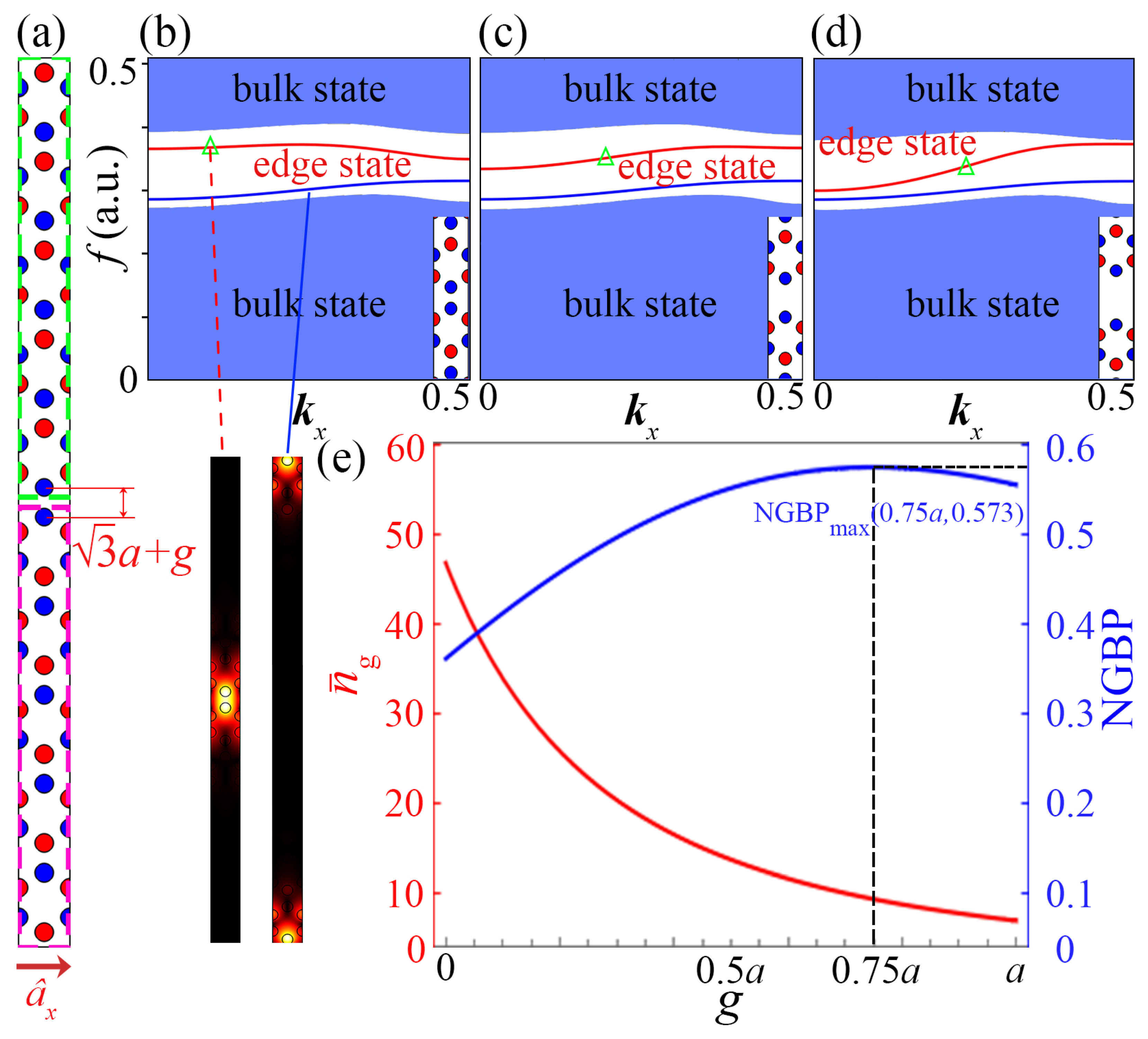
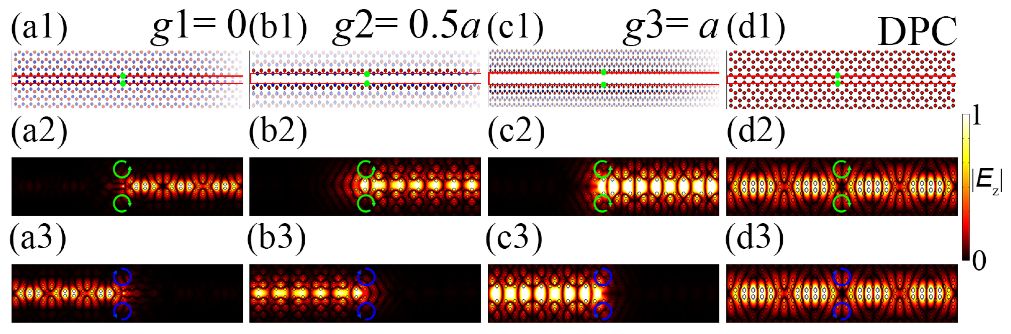
3. Tunable Slow Light in Valley-Locked PhC Waveguides

By breaking the spatial inversion symmetry, the originally degenerate bands split, creating valleys with opposite pseudospins at the K and K points, evident in their contrasting orbital angular momenta (OAM), which signifies the onset of valley-locked effect. Previous calculations indicate VTPC1 ( c v 1 = 1 ) and VTPC2 ( c v 2 = 1 ) have opposite valley Chern numbers. Thus, the mirror-symmetric supercell structure depicted in the figure can produce topologically protected edge states with a valley-locked effect. This imparts spin polarization to the topological edge states, enabling the chiral one-way transmission of incident light with selected polarization. For instance, VTPC1 supports right-handed circularly polarized light moving rightwards, while VTPC2 supports left-handed circularly polarized light moving rightwards. This characteristic allows for high robustness transmission even at sharp corners, a property we confirmed through subsequent topological property verification of the system during adjustment.
Leveraging the valley-locked effect and the properties of the K and K points, we constructed two PhC supercells using VTPC1 and VTPC2, each composed of 5 × 1 unit cells, as indicated by the green and purple frames in Figure 2a. This figure illustrates a compound photonic supercell comprising VTPC1, VTPC2, and an air gap. The opposite pseudospin directions of these two structures realize a valley topologically protected PhC waveguide.
Subsequently, we calculated the band structures as the parameter g varies from 0 to a. Figure 2b–d display the band diagrams of the compound PhC supercells with g 1 = 0 , g 2 = 0.5 a , and g 3 = a , respectively. The red curves denote the topological edge states of these supercells, protected by the valley-locked effect, with energy concentrated at the interface of the VTPC1–air–VTPC2 topological PhC waveguide. The blue curves show the edge states between the PhC’s upper/lower boundaries and air, with energy localized at the top of VTPC1 and the bottom of VTPC2, exhibiting higher energy loss during transmission. The blue regions signify the bulk states. It can be observed that, in the region marked by green triangles, the slope remains consistently positive throughout the continuous variation range of g, indicating that the group velocity is always positive in this region. Moreover, as g increases, the frequency range of the band structure gradually widens (the bandwidth variation with g is shown in Appendix A Figure A1b), suggesting the potential for broadband tunable group velocity control using this band.
To quantitatively analyze the slow-light capability of the topological mode in such topologically protected PhC waveguides, we calculate the average group index n ¯ g of the topological edge state, which is defined as follows [56,57]:
n ¯ g ( ω 0 ) = 1 Δ ω ω 0 Δ ω / 2 ω 0 + Δ ω / 2 n g ( ω ) d ω ,
where Δ ω is the range over which the group index n g ( ω 0 ) changes by 10 % in the edge state, and ω 0 is the center frequency of Δ ω . The group index n g ( ω ) = c / v g = c / ( d ω / d k ) , where c is the phase velocity, and v g is the group velocity. Then, we adopt an important parameter, normalized group index–bandwidth product (NGBP), to evaluate the slow-light characteristics [58]: NGBP = n ¯ g ( ω 0 ) × Δ ω ω 0 .
In Figure 2e, the red (blue) curve shows the relationship between the average group index ( n ¯ g ) and the normalized group index–bandwidth product (NGBP) as the gap width g changes. With increasing g, n ¯ g decreases and the normalized bandwidth increases (the relationship between the average group index and the normalized bandwidth ( Δ n g 10 % ) as g changes is shown in Appendix A). Specifically, when g = 0 , NGBP starts at 0.36, peaks at 0.571 near g = 0.75 a , then drops to 0.554. Meanwhile, n ¯ g decreases from 46 to 6.9. These results show that, within g [ 0 , a ] , both n ¯ g and NGBP are continuously tunable.
The existence of a maximum normalized group index–bandwidth product (NGBP) in our PhC model highlights a fundamental trade-off between the group index and bandwidth, originating from the constraints imposed by dispersion relations. In PhCs, the dispersion relation, which connects the normalized frequency f and wave vector k, governs the group index and bandwidth [59]. Near photonic bandgap edges or in flat-band regions, the dispersion curve flattens, resulting in a high group index n g and pronounced slow-light effects [60]. However, these flat dispersion regions are typically confined to narrow frequency ranges [61], as shown in Figure 2b–d, which further supports the observation that a large group index leads to a small bandwidth Δ f . This restriction implies that simultaneously achieving an extremely high group index and a very wide bandwidth is impossible. Thus, photonic crystal slow light, restricted by this physical limitation, has a maximum NGBP.
To verify the results obtained from our band calculations, we selected g 1 = 0 , g 2 = 0.5 a , and g 3 = a for comparison to demonstrate significant group delay. Wave packets with corresponding bandwidths were injected into three topologically protected PhC waveguides. Figure 3 illustrates the simulated intensity distributions of light waves in the topologically protected PhC waveguides at central frequencies f 1 = 0.369 , f 2 = 0.353 , and f 3 = 0.342 . For g 1 = 0 , the spatial distance Δ x 1 = 0.982 a between the centers of the wave packets at two arbitrary time points, 330 fs and 390 fs; for g 2 = 0.5 a , the spatial distance Δ x 2 = 16.725 a between the time points 390 fs and 690 fs; and, for g 3 = a , the spatial distance Δ x 3 = 16.456 a between the time points 240 fs and 390 fs, as shown in Figure 3(a2,a3,b2,b3,c2,c3), respectively. According to the formula for the group index n g = c ( Δ x / Δ t ) , the calculated group index is n g ( g 1 = 0 ) 46.71 , n g ( g 2 = 0.5 a ) 3.71 , and n g ( g 3 = a ) 6.967 . These results are consistent with our previous calculations shown in Figure 2e.
This method for modulating group velocity in our model is grounded in the valley-locked effect, achieved by adjusting the air-gap width of topologically protected PhC waveguides without altering the original structure. Instead of modifying the PhC rods’ size or dielectric constants, we can adjust n ¯ g and NGBP conveniently by changing the spacing between VTPC1 and VTPC2. This approach ensures robust light transmission in topologically protected PhC waveguides and enables broadband tunable slow light. To guarantee the topological protection of the gap during adjustment, we computationally verify two key topological features—chirality [62,63,64] and robustness [65,66,67]—which are well-known benchmarks in valley-locked PhCs [44,68].

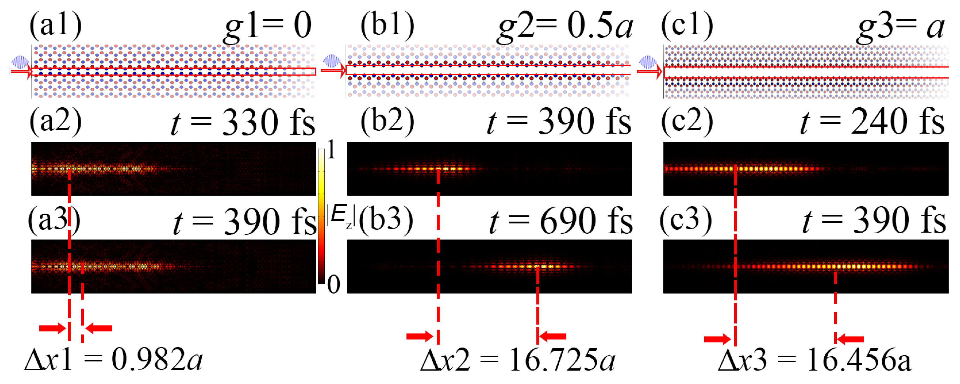
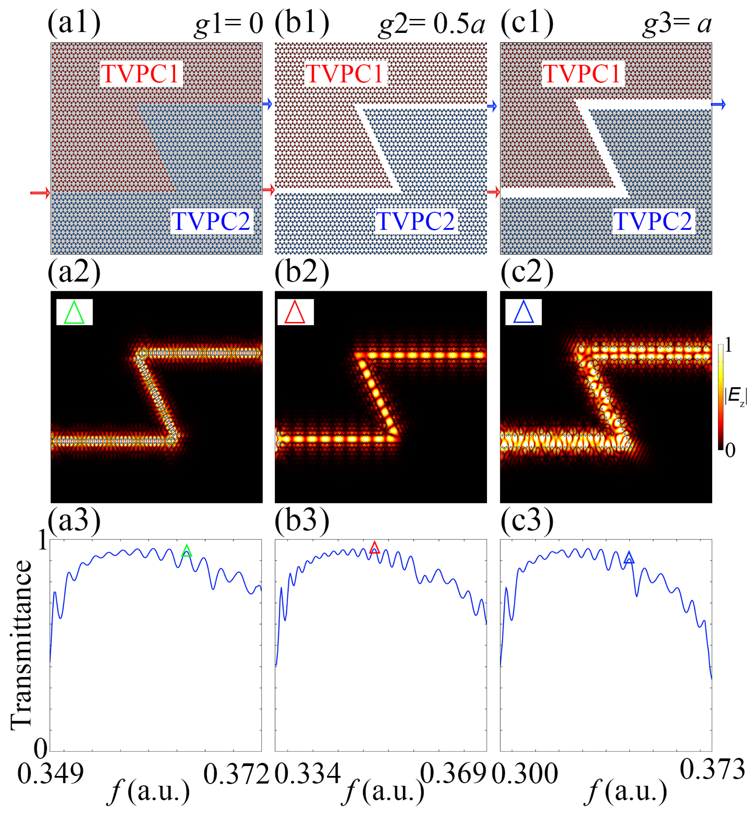
4. Topological Transmission Characteristics of Valley-Locked PhC Slow-Light Waveguides

To verify the topological transmission properties of the valley-locked topological slow light waveguides, we constructed straight waveguides for the three selected characteristic parameters of the topologically protected PhC waveguides, as shown in Figure 4(a1,b1,c1). As illustrated, two excitation sources with opposite orbital angular momentum characteristics (indicated by the green and blue circles) were placed in the waveguide to separately excite each straight waveguide.
The computational results are presented in Figure 4(a2,a3,b2,b3,c2,c3). The results show that, at the slow light central frequency, when excited by a pair of opposite green (blue) chiral sources, the light waves in the PhC waveguide always propagate to the right (left). Chiral excitation plots for more characteristic parameters are shown in Appendix B. In contrast, the light excited by the left-handed orbital angular momentum source always propagates to the left. This demonstrates that all three waveguides are valley-locked, and we can control the propagation direction of the light waves by using incident light with different orbital angular momenta. This showcases the chiral propagation characteristics of the valley-locked structure.
To verify the topological transmission properties of the valley-locked topological slow-light waveguides, we further calculated the propagation of topologically protected PhC waveguides with two sharp corners for the three characteristic parameters. The structures are shown in Figure 5(a1,b1,c1), where the red and blue arrows represent the input and output ports, respectively. We calculated the transmission rates for the three waveguides, with the results shown in Figure 5(a3,b3,c3). Figure 5(a2,b2,c2) show the transmission effects of the three structures, corresponding to the frequencies marked by the triangles in Figure 5(a3,b3,c3). As can be seen, even with two sharp corners, the transmission rates of the three structures remain at a high level under the protection of the valley-locked effect, demonstrating the robust transmission characteristics of this type of valley-locked tunable slow-light topologically protected PhC waveguide.

5. Summary

In this work, we designed a topological photonic slow-light waveguide with tunable group index and bandwidth, based on the honeycomb unit cell and leveraging the valley-locked effect. Initially, we computed the unit cell’s topological properties, including the band structure and topological edge states, to ensure the stability of the waveguide design. By adjusting the air gap between the two PhC layers, we achieved continuous tuning of the group index (from 47 to 6) and the normalized group index–bandwidth product (from 0.495 to 0.573), showing the flexibility of our approach. We also characterized the waveguide’s chiral propagation and propagation loss, observing robust transmission even after sharp corners, which suggests practical applications in complex photonic circuits.
Unlike traditional slow-light tuning methods, our approach adjusts the spacing between two PhCs without changing the dielectric constant or size of the medium rods, offering a simpler and more versatile solution. Experimentally, VTPC1 and VTPC2 can be built on separate substrates, using high-precision piezoelectric ceramics to control the g parameter. This method ensures tunability while maintaining the PhC’s unit cell structure, making it compatible with existing fabrication techniques. The tunable gap width allows precise control of the group velocity on photonic chips and realizes a topologically protected edge state robust to disorders, ensuring reliable performance in practical scenarios. These features make the system suitable for complex computations in light-based chips and for storing [49,50] and releasing optical signals in optical storage [52], with potential for future photonic devices. However, there are some limitations. First, modulating the group index by adjusting the air gap requires extremely high precision from devices like piezoelectric ceramics, which may increase the fabrication complexity and cost. Second, the honeycomb unit cell limits the design of waveguides with arbitrary bending angles, which could be a challenge for certain applications. Overall, our work provides a tunable platform for slow-light applications, contributing to advancements in photonic technologies such as on-chip optical communication, signal processing, and quantum computing.

Author Contributions

Conceptualization, C.P. and X.Q.; methodology, C.P., G.L. and X.Q.; software, C.P. and G.L.; validation, J.Y., C.M. and X.Q.; formal analysis, C.P.; investigation, C.P.; resources, X.Q.; data curation, C.P.; writing—original draft preparation, C.P.; writing—review and editing, X.Q.; visualization, C.P.; supervision, X.Q.; project administration, X.Q.; funding acquisition, X.Q. All authors have read and agreed to the published version of the manuscript.

Funding

This research was financially funded by the National Natural Science Foundation of China (NSFC) (No. 12174307).

Institutional Review Board Statement

Not applicable.

Informed Consent Statement

Not applicable.

Data Availability Statement

Data will be made available on request.

Conflicts of Interest

The authors declare no conflicts of interest.

Abbreviations

The following abbreviations are used in this manuscript:
PhCphotonic crystal
VTPCValley Topological Photonic Crystal
NGBPnormalized group index–bandwidth product

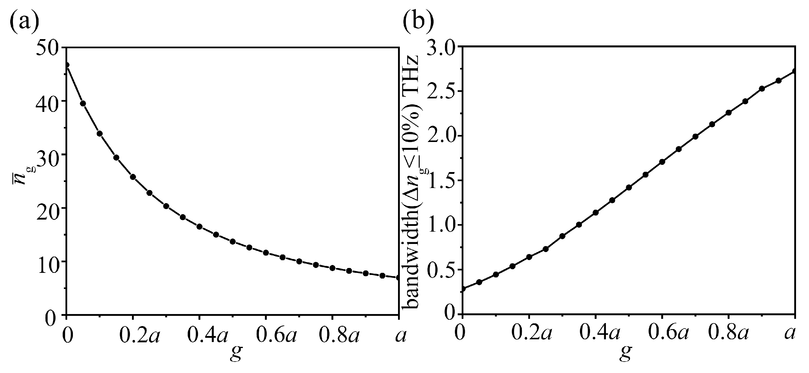
Appendix A. Group Index and Bandwidth Variation with g

To better illustrate the variation in the average group index and bandwidth with the change in g, we separately plotted the variation in the average group index and bandwidth with the parameter g, as shown in Figure A1a,b.
Figure A1. (a) Relationship between average group index and g; (b) relationship between bandwidth and group index.
Photonics 12 00332 g0a1

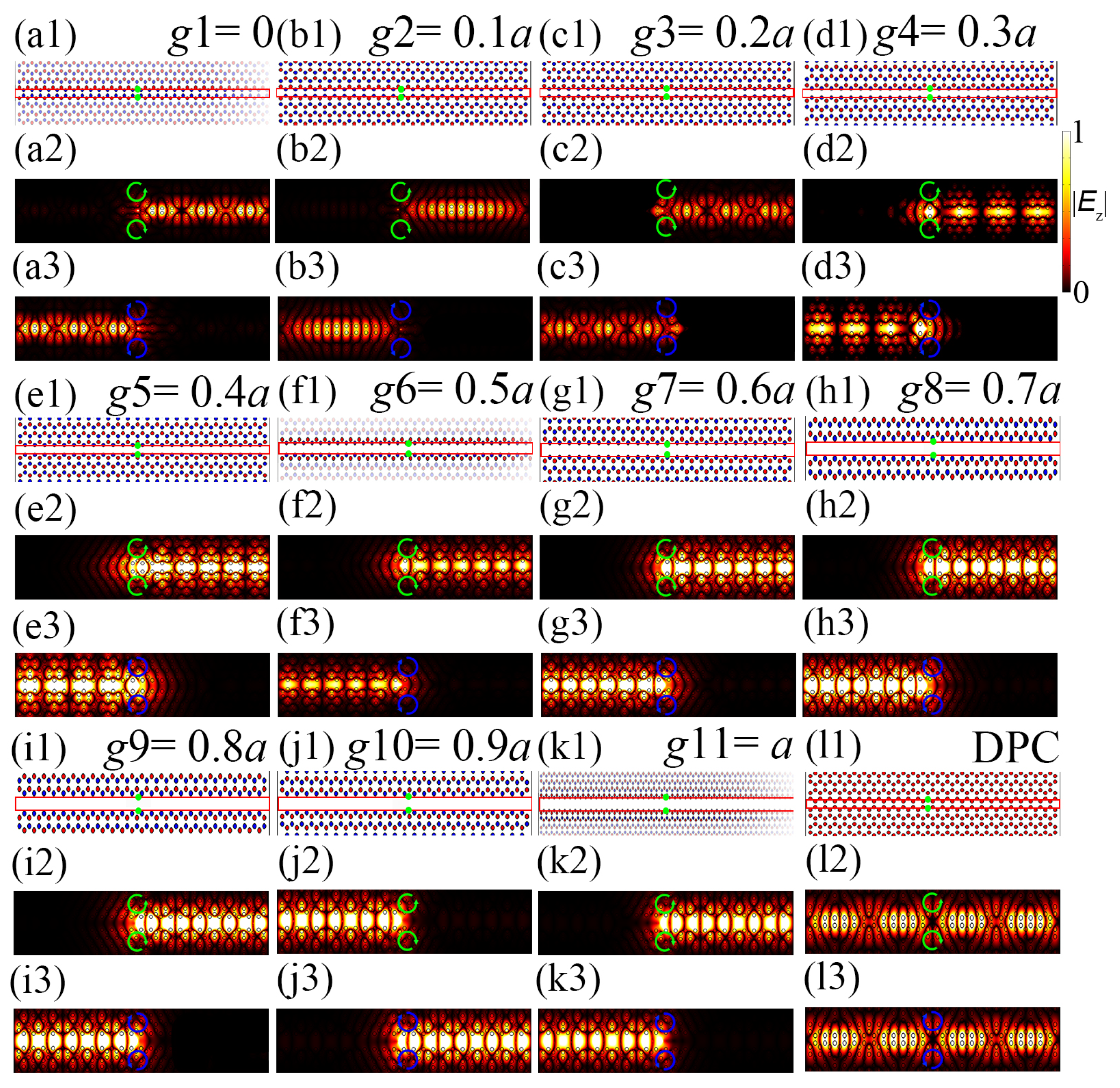
Appendix B. Chiral Validation Calculations of PhC Waveguide for More g Parameters

Figure A2. Chiral propagation analysis of PhC waveguide for different g parameters. (a1a3,b1b3,c1c3,d1d3,e1e3,f1f3,g1g3,h1h3,i1i3,j1j3,k1k3,l1l3) represent the computational results for the cases of g 1 = 0 , g 2 = 0.1 a , g 3 = 0.2 a , g 4 = 0.3 a , g 5 = 0.4 a , g 6 = 0.5 a , g 7 = 0.6 a , g 8 = 0.7 a , g 9 = 0.8 a , g 10 = 0.9 a , g 10 = 1.0 a and DPC, respectively.
Photonics 12 00332 g0a2
To more comprehensively verify the chiral characteristics of the PhC waveguide under different parameters, we performed validation calculations for the PhC waveguide with g varying in the range of [ 0 , a ] in steps of 0.1 a . As shown in Figure A2, the results indicate that the PhC waveguide exhibits chiral propagation characteristics across the entire range of g [ 0 , a ] .

References

  1. Haldane, F.D.M.; Raghu, S. Photonic topological insulators. Nat. Photonics 2013, 6, 58–62. [Google Scholar] [CrossRef]
  2. Maczewsky, L.J.; Zeuner, J.M.; Nolte, S.; Szameit, A. Observation of photonic anomalous Floquet topological insulators. Nat. Photonics 2014, 8, 821–829. [Google Scholar] [CrossRef]
  3. Khanikaev, A.B.; Shvets, G. Two-dimensional topological photonics. Nat. Photonics 2017, 11, 763–773. [Google Scholar] [CrossRef]
  4. Lu, C.; Sun, Y.Z.; Wang, C.; Zhang, H.; Zhao, W.; Hu, X.; Xiao, M.; Ding, W.; Liu, Y.-C.; Chan, C.T. On-chip nanophotonic topological rainbow. Nat. Commun. 2022, 13, 20236. [Google Scholar] [CrossRef]
  5. Regnault, N.; Xu, Y.; Li, M.R.; Ma, D.S.; Jovanovic, M.; Yazdani, A.; Parkin, S.S.P.; Felser, C.; Schoop, L.M.; Ong, N.P.; et al. Catalogue of flat-band stoichiometric materials. Nature 2022, 603, 824–828. [Google Scholar] [CrossRef] [PubMed]
  6. Chen, X.D.; Gao, Z.X.; Cui, X.; Mo, H.C.; Chen, W.J.; Zhang, R.Y.; Chan, C.T.; Dong, J.-W. Realization of Time-Reversal Invariant Photonic Topological Anderson Insulators. Phys. Rev. Lett. 2024, 133, 133802. [Google Scholar] [CrossRef]
  7. Zhu, W.; Li, L. A brief review of hybrid skin-topological effect. J. Phys. Condens. Matter 2024, 36, 253003. [Google Scholar] [CrossRef]
  8. Zhang, H.; Li, H.; Jiang, J.; Jiang, H.; Sun, Y.; Yang, Y.; Chen, H.; Guo, Z. Observation of robust polarization conversion via topological edge states in dimer chains. J. Opt. 2025, 27, 045401. [Google Scholar] [CrossRef]
  9. Harari, G.; Bandres, M.A.; Lumer, Y.; Rechtsman, M.C.; Chong, Y.D.; Khajavikhan, M.; Christodoulides, D.N.; Segev, M. Topological insulator laser: Experiment. Science 2018, 359, 4003. [Google Scholar] [CrossRef]
  10. Alù, A.; Pilozzi, L.; Xu, H.; Fan, J. Topological photonics and beyond: Introduction. Photonic Res. 2021, 9, TPB1–TPB2. [Google Scholar] [CrossRef]
  11. Wu, H.C.; Xu, H.S.; Xie, L.C.; Jin, L. Edge State, Band Topology, and Time Boundary Effect in the Fine-Grained Categorization of Chern Insulators. Phys. Rev. Lett. 2024, 132, 083801. [Google Scholar] [CrossRef]
  12. Rechtsman, M.C.; Zeuner, J.M.; Plotnik, Y.; Lumer, Y.; Podolsky, D.; Dreisow, F.; Nolte, S.; Segev, M.; Szameit, A. Photonic Floquet topological insulators. Nature 2013, 496, 196–200. [Google Scholar] [CrossRef] [PubMed]
  13. Leykam, D.; Rechtsman, M.C.; Chong, Y.D. Anomalous Topological Phases and Unpaired Dirac Cones in Photonic Floquet Topological Insulators. Phys. Rev. Lett. 2016, 117, 013902. [Google Scholar] [CrossRef] [PubMed]
  14. Khanikaev, A.B.; Mousavi, S.H.; Tse, W.-K.; Kargarian, M.; MacDonald, A.H.; Shvets, G. Photonic topological insulators. Nat. Mater. 2012, 6, 158–163. [Google Scholar] [CrossRef]
  15. Wu, L.H.; Hu, X. Scheme for achieving a topological photonic crystal by using dielectric material. Phys. Rev. Lett. 2015, 114, 223901. [Google Scholar] [CrossRef]
  16. Kang, Y.; Ni, X.; Cheng, X.; Khanikaev, A.B.; Genack, A.Z. Pseudo-spin–valley coupled edge states in a photonic topological insulator. Nat. Commun. 2018, 9, 3029. [Google Scholar] [CrossRef] [PubMed]
  17. Ni, X.; Purtseladze, D.; Smirnova, D.A.; Slobozhanyuk, A.; Alù, A.; Khanikaev, A.B. Spin- and valley-polarized one-way Klein tunneling in photonic topological insulators. Sci. Adv. 2018, 4, 8802. [Google Scholar] [CrossRef]
  18. Bower, E.; Giles, R.F.L.; Martin, A.M. The effects of substrate temperature on the properties of pulsed laser deposited YBCO films. New J. Phys. 2016, 18, 025012. [Google Scholar] [CrossRef]
  19. He, X.-T.; Liang, E.-T.; Yuan, J.-J.; Qiu, H.-Y.; Chen, X.-D.; Zhao, F.-L.; Dong, J.-W. A silicon-on-insulator slab for topological valley transport. Nat. Commun. 2019, 10, 872. [Google Scholar] [CrossRef]
  20. Wang, Y.; Wang, H.-X.; Liang, L.; Zhu, W.; Fan, L.; Lin, Z.-K.; Li, F.; Zhang, X.; Luan, P.-G.; Poo, Y.; et al. Hybrid topological photonic crystals. Nat. Commun. 2023, 14, 4457. [Google Scholar] [CrossRef]
  21. Cheng, X.; Genack, A.Z.; Khanikaev, A.B. Photonic Topological Insulators: A New Route to Unidirectional Waveguides. Adv. Opt. Mater. 2017, 5, 1700357. [Google Scholar] [CrossRef]
  22. Khanikaev, A.B.; Zhang, Y.Z.; Xiao, S.; Cheshkov, A.; Merai, A.; Shvets, G. Nonlinear light generation in topological nanostructures. Nat. Nanotechnol. 2018, 14, 126. [Google Scholar] [CrossRef]
  23. Cheng, X.; Genack, A.Z.; Khanikaev, A.B. Nonlinear light generation in topological nanostructures. Appl. Phys. Lett. 2018, 112, 233106. [Google Scholar] [CrossRef]
  24. Kirsch, M.S.; Zhang, Y.; Kremer, M.; Maczewsky, L.J.; Ivanov, S.K.; Kartashov, Y.V.; Torner, L.; Bauer, D.; Szameit, A.; Heinrich, M. Nonlinear second-order photonic topological insulators. Nat. Phys. 2021, 17, 995–1000. [Google Scholar] [CrossRef]
  25. Barik, S.; Karasahin, A.; Flower, C.; Cai, T.; Miyake, H.; DeGottardi, W.; Hafezi, M.; Waks, E. A topological quantum optical interface. Science 2018, 359, 666–668. [Google Scholar] [CrossRef] [PubMed]
  26. Zhang, Y.Z.; Ivanov, S.K.; Kartashov, Y.V.; Torner, L. Nonlinear higher-order polariton topological insulator. Phys. Rev. Lett. 2020, 124, 083603. [Google Scholar] [CrossRef]
  27. Chen, X.-D.; Deng, W.-M.; Shi, F.-L.; Zhao, F.-L.; Chen, M.; Dong, J.-W. Direct Observation of Corner States in Second-Order Topological Photonic Crystal Slabs. Phys. Rev. Lett. 2019, 122, 233902. [Google Scholar] [CrossRef]
  28. Li, M.; Liu, Y.; Du, L.; Li, P.; Dong, Y.; Tao, L.; Li, Z.; Guo, Y.; Song, K.; Zhao, X. Ultrabroadband valley transmission and corner states in valley photonic crystals with dendritic structure. Commun. Phys. 2024, 7, 214. [Google Scholar] [CrossRef]
  29. Canyellas, R.; Liu, C.; Arouca, R.; Eek, L.; Wang, G.; Yin, Y.; Guan, D.; Li, Y.; Wang, S.; Zheng, H.; et al. Topological edge and corner states in bismuth fractal nanostructures. Nat. Phys. 2024, 20, 1421–1428. [Google Scholar] [CrossRef]
  30. Barone, A.; Clementi, M.; Poempool, T.; Marcia, A.; Bajoni, D.; Liscidini, M.; Gerace, D.; Fromherz, T.; Galli, M. Generation of entangled photon pairs from a silicon bichromatic photonic crystal cavity. APL Photonics 2024, 9, 016110. [Google Scholar] [CrossRef]
  31. Gao, Y.F.; He, Y.H.; Li, Y.; Rouzi, S.; Jin, M.C.; He, Y.; Zhou, S.Y. Topological waveguide-cavity coupling system based on valley photonic crystals. Opt. Laser Technol. 2024, 175, 110799. [Google Scholar] [CrossRef]
  32. Rechtsman, M.C. Reciprocal topological photonic crystals allow backscattering. Nat. Photonics 2023, 17, 383–384. [Google Scholar] [CrossRef]
  33. Rosiek, C.A.; Arregui, G.; Vladimirova, A.; Albrechtsen, M.; Vosoughi Lahijani, B.; Christiansen, R.E.; Stobbe, S. Observation of strong backscattering in valley-Hall photonic topological interface modes. Nat. Photonics 2023, 17, 386–392. [Google Scholar] [CrossRef]
  34. Liu, G.G.; Gao, Z.; Wang, Q.; Xi, X.; Hu, Y.H.; Wang, M.; Liu, C.; Lin, X.; Deng, L.; Yang, S.A.; et al. Topological Chern vectors in three-dimensional photonic crystals. Nature 2023, 609, 53–59. [Google Scholar] [CrossRef] [PubMed]
  35. Chen, J.; Liang, W.; Li, Z.Y. Broadband dispersionless topological slow light. Opt. Lett. 2020, 45, 4964–4967. [Google Scholar] [CrossRef]
  36. Yoshimi, H.; Yamaguchi, T.; Ota, Y.; Arakawa, Y.; Iwamoto, S. Slow light waveguides in topological valley photonic crystals. Opt. Lett. 2020, 45, 2648–2651. [Google Scholar] [CrossRef]
  37. Chen, Yafeng and Lan, Zhihao and Li, Jensen and Zhu, Jie Topologically protected second harmonic generation via doubly resonant high-order photonic modes. Phys. Rev. B 2021, 104, 155421. [CrossRef]
  38. Luo, H.; Sohn, S.S.; Lu, W.; Li, L.; Li, X.; Soundararajan, C.K.; Krieger, W.; Li, Z.; Raabe, D. A strong and ductile medium-entropy alloy resists hydrogen embrittlement and corrosion. Nat. Commun. 2020, 11, 3081. [Google Scholar] [CrossRef]
  39. Kumar, A.; Tan, Y.J.; Navaratna, N.; Gupta, M.; Pitchappa, P.; Singh, R. Slow light topological photonics with counter-propagating waves and its active control on a chip. Nat. Commun. 2024, 15, 926. [Google Scholar] [CrossRef]
  40. Hau, L.V.; Harris, S.E.; Dutton, Z.; Behroozi, C.H. Light speed reduction to 17 metres per second in an ultracold atomic gas. Nature 1999, 397, 594–598. [Google Scholar] [CrossRef]
  41. Ding, D.S.; Zhang, W.; Zhou, Z.Y.; Shi, S.; Xiang, G.Y.; Wang, X.S.; Jiang, Y.K.; Shi, B.S.; Guo, G.C. Quantum Storage of Orbital Angular Momentum Entanglement in an Atomic Ensemble. Phys. Rev. Lett. 2015, 114, 050502. [Google Scholar] [CrossRef]
  42. Wang, Z.; Chong, Y.D.; Joannopoulos, J.D.; Soljačić, M. Observation of unidirectional backscattering-immune topological electromagnetic states. Nature 2009, 461, 772–775. [Google Scholar] [CrossRef]
  43. Arregui, G.; Gomis-Bresco, J.; Sotomayor-Torres, C.M.; Garcia, P.D. Quantifying the Robustness of Topological Slow Light. Phys. Rev. Lett. 2021, 126, 027403. [Google Scholar] [CrossRef] [PubMed]
  44. Zheng, W.; Wang, Y. Topological slow light waveguide in photonic valley-locked heterostructures. Phys. Scripta 2023, 98, 065508. [Google Scholar] [CrossRef]
  45. Luan, E.; Shoman, H.; Ratner, D.M.; Cheung, K.C.; Chrostowski, L. Silicon Photonic Biosensors Using Label-Free Detection. Sensors 2018, 18, 3519. [Google Scholar] [CrossRef] [PubMed]
  46. Qin, J.; Jiang, S.; Wang, Z.; Cheng, X.; Li, B.; Shi, Y.; Tsai, D.P.; Liu, A.Q.; Huang, W.; Zhu, W. Metasurface Micro/Nano-Optical Sensors: Principles and Applications. ACS Nano 2022, 16, 11598–11618. [Google Scholar] [CrossRef] [PubMed]
  47. Barik, S.; Karasahin, A.; Mittal, S.; Waks, E.; Hafezi, M. Chiral quantum optics using a topological resonator. Phys. Rev. B 2020, 101, 205303. [Google Scholar] [CrossRef]
  48. Ji, K.; Zhong, Q.; Ge, L.; Beaudoin, G.; Sagnes, I.; Raineri, F.; El-Ganainy, R.; Yacomotti, A.M. Tracking exceptional points above the lasing threshold. Nat. Commun. 2023, 14, 8304. [Google Scholar] [CrossRef]
  49. Kuramochi, E.; Nozaki, K.; Shinya, A.; Takeda, K.; Sato, T.; Matsuo, S.; Taniyama, H.; Sumikura, H.; Notomi, M. Large-scale integration of wavelength-addressable all-optical memories on a photonic crystal chip. Nat. Photonics 2014, 8, 474–481. [Google Scholar] [CrossRef]
  50. Zhong, T.; Kindem, J.M.; Bartholomew, J.G.; Rochman, J.; Craiciu, I.; Miyazono, E.; Bettinelli, M.; Cavalli, E.; Verma, V.; Nam, S.W.; et al. Nanophotonic rare-earth quantum memory with optically controlled retrieval. Science 2017, 357, 1392–1395. [Google Scholar] [CrossRef]
  51. Lodahl, P.; Mahmoodian, S.; Stobbe, S. Interfacing single photons and single quantum dots with photonic nanostructures. Rev. Mod. Phys. 2015, 87, 347–400. [Google Scholar] [CrossRef]
  52. Wang, Y.; Fei, H.; Lin, H.; Bai, J.; Zhang, M.; Liu, X.; Cao, B.; Tian, Y.; Xiao, L. Ultra-compact electro-optic phase modulator based on a lithium niobate topological slow light waveguide. Opt. Express 2024, 32, 3980. [Google Scholar] [CrossRef] [PubMed]
  53. Chen, X.D.; Zhao, F.L.; Chen, M.; Dong, J.W. Valley-contrasting physics in all-dielectric photonic crystals: Orbital angular momentum and topological propagation. Phys. Rev. B 2017, 96, 020202. [Google Scholar] [CrossRef]
  54. Wang, C.; Zhang, H.; Yuan, H.; Zhong, J.; Lu, C. Universal numerical calculation method for the Berry curvature and Chern numbers of typical topological photonic crystals. Front. Optoelectron. 2020, 13, 73–88. [Google Scholar] [CrossRef]
  55. Zhao, R.; Xie, G.-D.; Chen, M.L.N.; Lan, Z.; Huang, Z.; Sha, W.E.I. First-principle calculation of Chern number in gyrotropic photonic crystals. Opt. Express 2020, 28, 4638–4649. [Google Scholar] [CrossRef]
  56. Hughes, S.; Ramunno, L.; Young, J.F.; Sipe, J.E. Extrinsic optical scattering loss in photonic crystal waveguides: Role of fabrication disorder and photon group velocity. Phys. Rev. Lett. 2005, 94, 033903. [Google Scholar] [CrossRef]
  57. Mori, D.; Baba, T. Wideband and low dispersion slow light by chirped photonic crystal coupled waveguide. Opt. Express 2005, 13, 9398–9408. [Google Scholar] [CrossRef]
  58. Liu, S.; Lu, W.; Lin, Z.; Chui, S.T. Magnetically controllable unidirectional electromagnetic waveguiding devices designed with metamaterials. Appl. Phys. Lett. 2010, 97, 201113. [Google Scholar] [CrossRef]
  59. Baba, T. Slow light in photonic crystals. Nat. Photonics 2008, 2, 465–473. [Google Scholar] [CrossRef]
  60. Vlasov, Y.A.; O’Boyle, M.; Hamann, H.F.; McNab, S.J. Active control of slow light on a chip with photonic crystal waveguides. Nature 2005, 438, 65–69. [Google Scholar] [CrossRef]
  61. Liang, Y.; Peng, C.; Sakai, K.; Iwahashi, S.; Noda, S. Three-dimensional coupled-wave analysis for square-lattice photonic crystal surface emitting lasers with transverse-electric polarization: Finite-size effects. Opt. Express 2012, 20, 15945. [Google Scholar] [CrossRef] [PubMed]
  62. Tang, G.J.; Chen, X.D.; Sun, L.; Guo, C.H.; Li, M.Y.; Tian, Z.T.; Chen, H.H.; Wang, H.W.; Sun, Q.Y.; Pan, Y.D.; et al. Broadband and fabrication-tolerant 3-dB couplers with topological valley edge modes. Light. Sci. Appl. 2024, 13, 166. [Google Scholar] [CrossRef]
  63. Jalali Mehrabad, M.; Foster, A.P.; Martin, N.J.; Dost, R.; Clarke, E.; Patil, P.K.; Skolnick, M.S.; Wilson, L.R. Chiral topological add–drop filter for integrated quantum photonic circuits. Optica 2023, 10, 415. [Google Scholar] [CrossRef]
  64. Kumar, A.; Gupta, M.; Pitchappa, P.; Wang, N.; Szriftgiser, P.; Ducournau, G.; Singh, R. Phototunable chip-scale topological photonics: 160 Gbps waveguide and demultiplexer for THz 6G communication. Nat. Commun. 2022, 13, 5404. [Google Scholar] [CrossRef] [PubMed]
  65. He, L.; Ji, H.Y.; Wang, Y.J.; Zhang, X.D. Topologically protected beam splitters and logic gates based on two-dimensional silicon photonic crystal slabs. Opt. Express 2020, 28, 34015. [Google Scholar] [CrossRef]
  66. Wang, H.; Sun, L.; He, Y.; Tang, G.; An, S.; Wang, Z.; Du, Y.; Zhang, Y.; Yuan, L.; He, X.; et al. Asymmetric Topological Valley Edge States on Silicon-On-Insulator Platform. Laser Photonics Rev. 2022, 16, 2100631. [Google Scholar] [CrossRef]
  67. Zhang, P.; Zhang, J.; Gu, L.; Fang, L.; Zhang, Y.; Zhao, J.; Gan, X. Compact on-chip power splitter based on topological photonic crystal. Opt. Mater. Express 2024, 14, 1390. [Google Scholar] [CrossRef]
  68. Shao, H.; Wang, Y.; Yang, G.; Sang, T. Topological transport in heterostructure of valley photonic crystals. Opt. Express 2023, 31, 32393. [Google Scholar] [CrossRef]
Figure 1. Construction of unit cell and its band structure. (a) Structures of DPC, VTPC1, and VTPC2, where red and blue represent two different dielectric materials ε a and ε b , respectively; (b) band structure of DPC; (c) band structure of VTPC1; (d,f) Berry curvature of the 1st and 2nd bands in (c); (e) phase diagrams (OAM) of K and K in (c).
Photonics 12 00332 g001
Figure 2. Configuration of a compound photonic supercell and its simulated physical properties. (a) A supercell of the compound PhC structure; (bd) band structures for g 1 = 0 , g 2 = 0.5 a , and g 3 = a , respectively; (e) variation in NGBP and n ¯ g with different values of g.
Photonics 12 00332 g002
Figure 3. Temporal evolutions of input Gaussian pulses in three PhC waveguides. (a1) PhC waveguides with g 1 = 0 . (a2,a3) Intensity distributions of the input Gaussian pulse at t = 330 fs and 390 fs, respectively. (b1) PhC waveguides with g 2 = 0.5 a . (b2,b3) Intensity distributions of the input Gaussian pulse at t = 390 fs and 690 fs. (c1) PhC waveguides with g 3 = a . (c2,c3) Intensity distributions of the input Gaussian pulse at t = 240 fs and 390 fs, respectively. Red arrows indicate the incident site and direction.
Photonics 12 00332 g003
Figure 4. Chiral propagation analysis of PhC waveguides (a1a3,b1b3,c1c3,d1d3) represent the computational results for the cases of g 1 = 0 , g 2 = 0.5 a , g = a , and DPC, respectively.
Photonics 12 00332 g004
Figure 5. Robust transmission analysis of slow-light valley-locked topological protect PhC waveguides: (a1,b1,c1) depict photonic waveguide structures with two sharp corners, where the red arrow indicate the input port of the wave packet and the blue arrow denote the output port, respectively; (a2,b2,c2) show the excitation effects of the photonic waveguides for three sets of parameters, with excitation frequencies corresponding to the points marked by triangles in (a3,b3,c3); (a3,b3,c3) present the transmission rate diagrams for the three photonic waveguides.
Photonics 12 00332 g005
Disclaimer/Publisher’s Note: The statements, opinions and data contained in all publications are solely those of the individual author(s) and contributor(s) and not of MDPI and/or the editor(s). MDPI and/or the editor(s) disclaim responsibility for any injury to people or property resulting from any ideas, methods, instructions or products referred to in the content.

