1. Introduction
With the fast deployment of 5G mobile networks [
1,
2,
3], more and more industries are convergent on the 5G technology for their communication support [
4,
5,
6]. Many industries have control signals with the requirements of high reliability and security. For the 5G grid application scenario, control, monitoring and management of power plants, distribution and utility networks need to be highly reliable and with guaranteed bandwidth. Otherwise, a single power plant failure with no timely countermeasure may cause the failure of the whole smart grid. For the 5G healthcare scenario, medical remote control includes remote ultrasound, remote endoscopy, remote emergency treatment, and remote surgery [
7]. The services require highly reliable transport tunnels with hard isolation. In the upcoming 5G-A and 6G era [
8,
9,
10,
11], new services and technical capabilities, including unmanned aerial vehicles (UAV), AV, artificial intelligence (AI)/machine learning (ML) and metaverse are expected to be supported. These new services also introduce demands for higher reliability. Taking the sensing service of UAV trajectory tracking as an example [
12], the transport network needs to accommodate the real-time reliable control and command instructions for the UAVs.
The transport network provides the connections among the 5G remote radio unit (RRU), distributed unit (DU), centralized unit (CU), and core network [
13]. Reliability mechanisms should be used in the 5G transport network as necessary to meet the requirements of the services being carried over the 5G network. The transport network is in general a multi-service network, and in most cases, a common transport network infrastructure will be shared between 5G services and other types of services [
14]. In addition to the requirements of 5G services, the transport network also needs to ensure the reliability of some important fixed dedicated line services.
In optical networking, time division multiplexing (TDM) technology provides better hard isolation characteristics and reliability compared to packet-based networks, and has been favored in 5G transport networks [
15]. Protection technology is one of the most crucial technical solutions for ensuring the reliability of transport networks [
16,
17]. Protection utilizes the pre-assigned capacity between nodes in order to allow a network to switch affected traffic to the protection channels in the event of an impairment. The protection mechanisms are mainly divided into optical layer protection and electrical layer protection. Optical layer protection provides optical line protection through multiple pairs of optical fibers, while electrical layer protection provides more flexible traffic protection [
18,
19]. According to the different protection topology and architecture, electrical layer protection can be divided into linear protection and ring protection [
20,
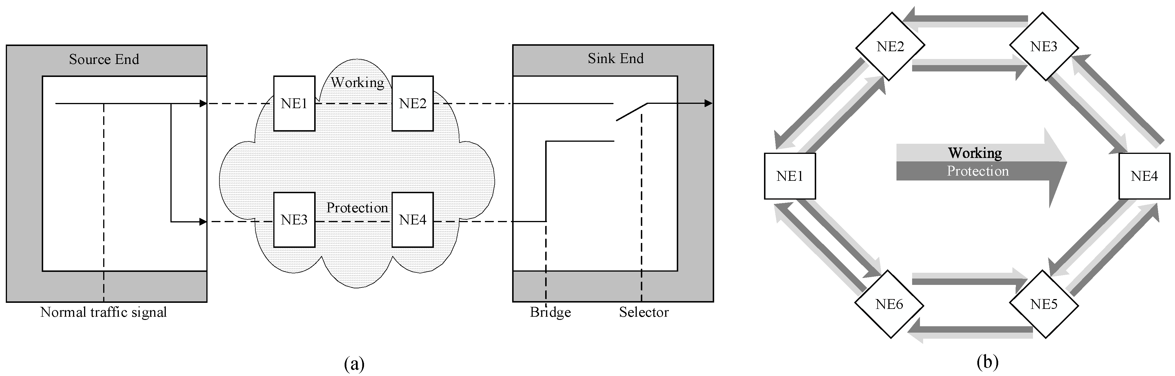
21], as shown in
Figure 1. Linear protection is the most widely used in electrical layer protection. In the 1 + 1 linear protection architecture, the normal traffic on working and protection transport channels is transmitted simultaneously to the sink endpoint of the protected domain where a selection between the working and protection transport channel is made.
The current protection mechanism adopts a single bridge to implement an end-to-end protection mechanism, in which a failure in the working channel triggers an end-to-end channel change to the protection channel. Under the background of the ever-increasing demand for cross domain data transmission and reliability, the current optical line protection and electrical layer linear protection are confronted with challenges, including difficulties in connecting cross domain networks and an inability to address multi-point fault scenarios. Recent advances in network protection have introduced control-plane-based solutions to address multi-point failures, such as routing reconfiguration approaches [
22,
23,
24]. While these approaches require multiple rounds of multi node interaction at the device and network management layers when handling complex failure scenarios, the protection switching times for recovery is hard to meet 50 ms protection time threshold [
25].
Meanwhile, enhancing nodal resilience could provide more systemic benefits than optimizing protection algorithms alone. So, it is important to provide node resiliency, which the dual node interconnection (DNI) topology across domains can support to address the failure of a single interconnection node. Ring protection based on the ring automatic protection switching supports DNI, and the protocol of was developed as ITU-T Recommendation G.8032 [
26]. However, the protection configuration across multi-domain ring networks is quite complex and lacks practicality. Linear protection technology with DNI has been explored in ITU-T G.Suppl.60 [
27]. However, the mechanism is limited to a linear protection domain where one end node connects to two interconnected nodes, while it is not applicable for domains in the middle of cascaded networks.
In this paper, we propose a novel cross-domain protection mechanism based on segmented dual-node interconnection (DNI). By constructing a DNI topology between two adjacent domains and leveraging the three-point bridging capability in the inter-domain nodes, the service can be switched from the faulty link to a normal link. A state interaction mechanism between DNI nodes is designed to deliver the detected fault status and complete the switching. The DNI-based cross-domain protection mechanism can isolate the faults in the faulty domains, and effectively resist multiple faults, and provide superior protection switching time performances. We experimentally validated the proposed protection mechanism in a commercial multi-domain, multi-vendor network, demonstrating effective protection for services spanning over 2700 km under various fault scenarios, including intra-domain and inter-domain faults. The proposed protection mechanism significantly outperforms the traditional linear protection mechanisms.
2. Key Performance Metrics of Protection Mechanisms
2.1. Protection Switching Time
Protection switching time is a critical parameter for evaluating the performance of protection switching mechanisms. It is defined as the time interval between the initiation of protection switching operations (e.g., the detection of a failure or degradation condition) and the completion of these operations. During the protection switching process, the traffic signals may be damaged, resulting in packet loss or other forms of signal degradation. Consequently, the duration of protection switching time directly impacts the integrity of the traffic signal. In order to make the services insensitive to protection switching of the transport channels, the protection switching time is expected to be less than 50 ms.
Protection switching time Tp consists of two parts, one is protection switching operations time T1, which is the time interval between the start of the protection switching operations (e.g., the confirmation of a failure or degradation condition) and the completion of the processing and transmission of the control signals required to effect protection switching; and the other is protection switching transfer time T2, which is the time interval between completion of the processing and transmission of the control signals required to effect protection switching and the completion of protection switching operations.
2.2. Protection Scenario
With the development of new services, some services require long-distance transport across domains. The traditional protection method requires end-to-end protection switching. When a single point fails, protection switching occurs in all domains, making it impossible to achieve fault isolation between domains.
In addition, long-distance cross domain transport also increases the possibility of multi-point failures on the transport path. Traditional protection methods cannot migrate traffic to connected paths if both the working and protection channels experience failures simultaneously.
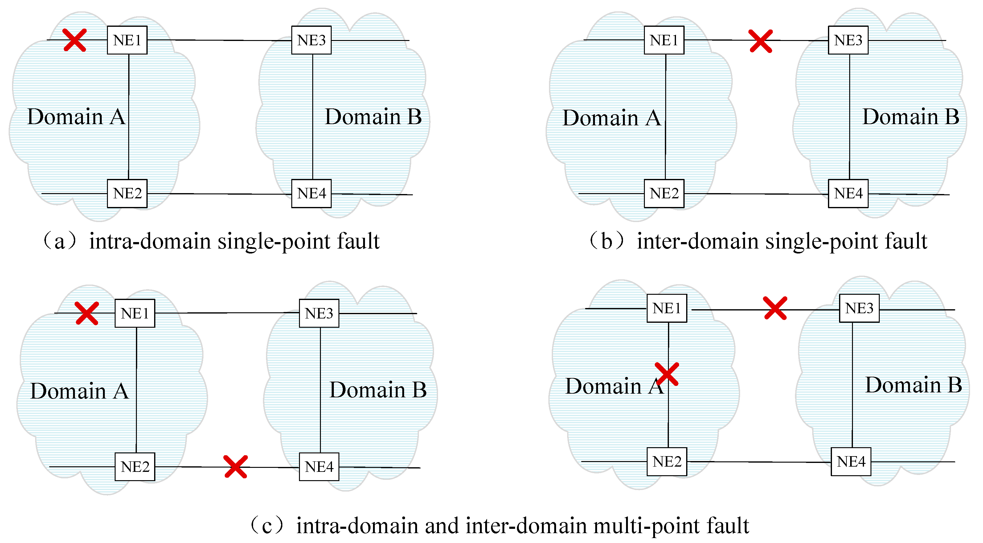
Figure 2 depicts cross domain networking under fault scenarios, which traditional protection methods fail to address while ensuring the non-faulty domain unaffected. Fault scenarios can be divided into an intra-domain single-point fault, inter-domain single-point fault, intra-domain and inter-domain multi-point fault, and so on. Cross domain protection schemes need to cover these scenarios and resist multi-point faults.
3. Principle of the Novel Cross-Domain Protection Mechanism
To enhance the network reliability against potential multi-point failures and improve the ability to realize fault isolation, a new protection technology based on DNI for cross domain protection is proposed. The central mechanism of DNI protection lies in three key aspects: (1) At the edge nodes across domains, a dual-node networking architecture is adopted to mitigate the risk of service interruption caused by single interconnection node failure. (2) A flexible bridge relationship is established between inter-domain and intra-domain connections through an innovative three-point bridge mechanism within each pair of DNI nodes. (3) Periodic interactive messages are introduced to propagate node and channel status information between DNI nodes, which enables collaborative protection across domains. This DNI-based cross-domain protection mechanism protection technique breaks through the barriers of domain and vendor segmentation in dedicated networks across domains. Deploying the consistent three-point bridge mechanism facilitates the domain-specific handling of faults. By leveraging the robustness and flexibility of the DNI architecture and bridge mechanism, this approach provides a more reliable and efficient protection strategy for cross domain networking. It effectively resolves fault isolation between different domains and resists multi-point failures in long-distance transmission.
3.1. Structure of Dual-Node Model
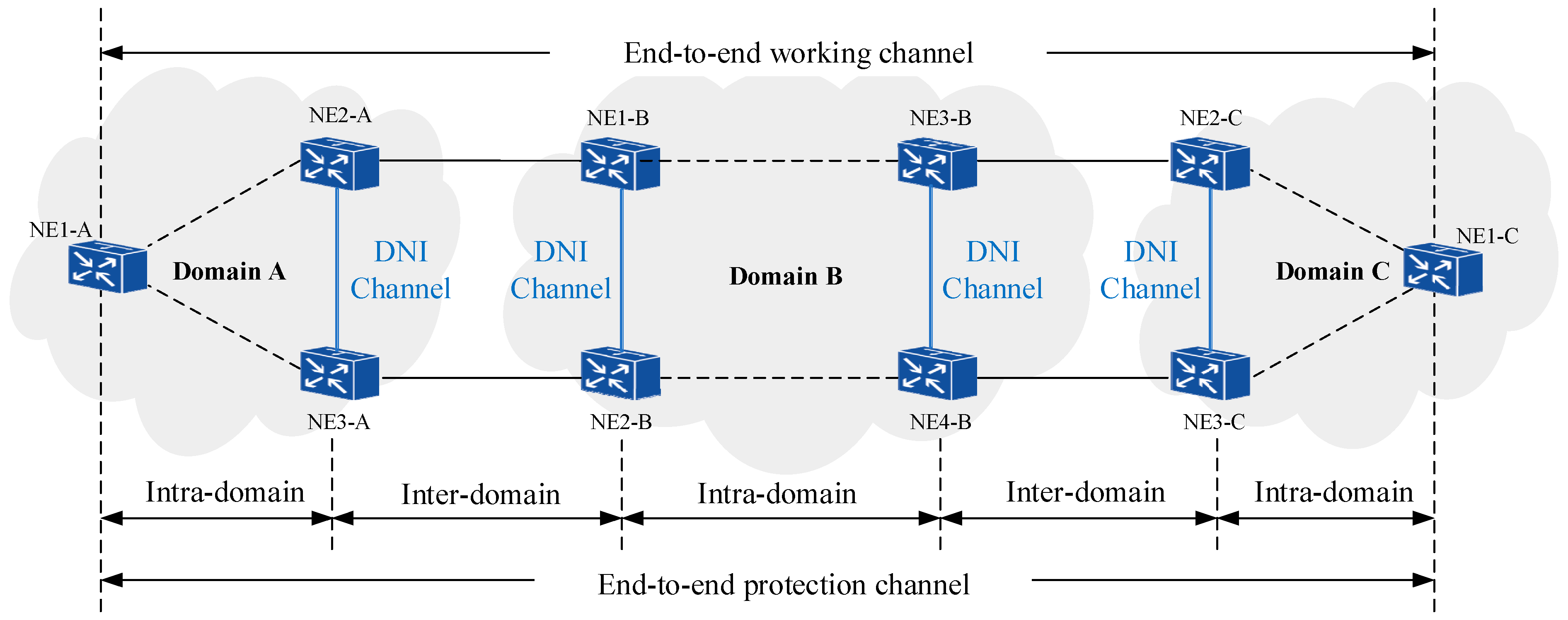
DNI protection is a segmented protection switching technology. As shown in
Figure 3, the dual-node model functions at the edge nodes of cross domains, forming an interconnection networking mode with two pairs of nodes. A pair of nodes consists of the DNI master node and DNI backup node, which cooperate with each other via the DNI channel to complete the protection function of the cross domain network. This structure with a pair of nodes can resist the risk of service interruption caused by the failure of a single interconnection node.
In
Figure 3, the source node NE1-A in Domain A and the DNI master/backup nodes (NE2-A, NE3-A) at the edge of the domain constitute 1+1 linear protection in the domain, and the inter-domain DNI nodes constitute 1+1 linear protection based on the inter-domain working channel and the inter-domain protection channel. The DNI master node and the DNI backup node operate protection state machines separately, making decisions and modifying channel cross-connections based on the fault status changes of the working/protection channels and DNI channels. The channel cross-connection change is achieved by the bridges and selectors in two pairs of nodes, thereby enabling rapid protection switching of service paths.
3.2. Three-Point Bridge Mechanism
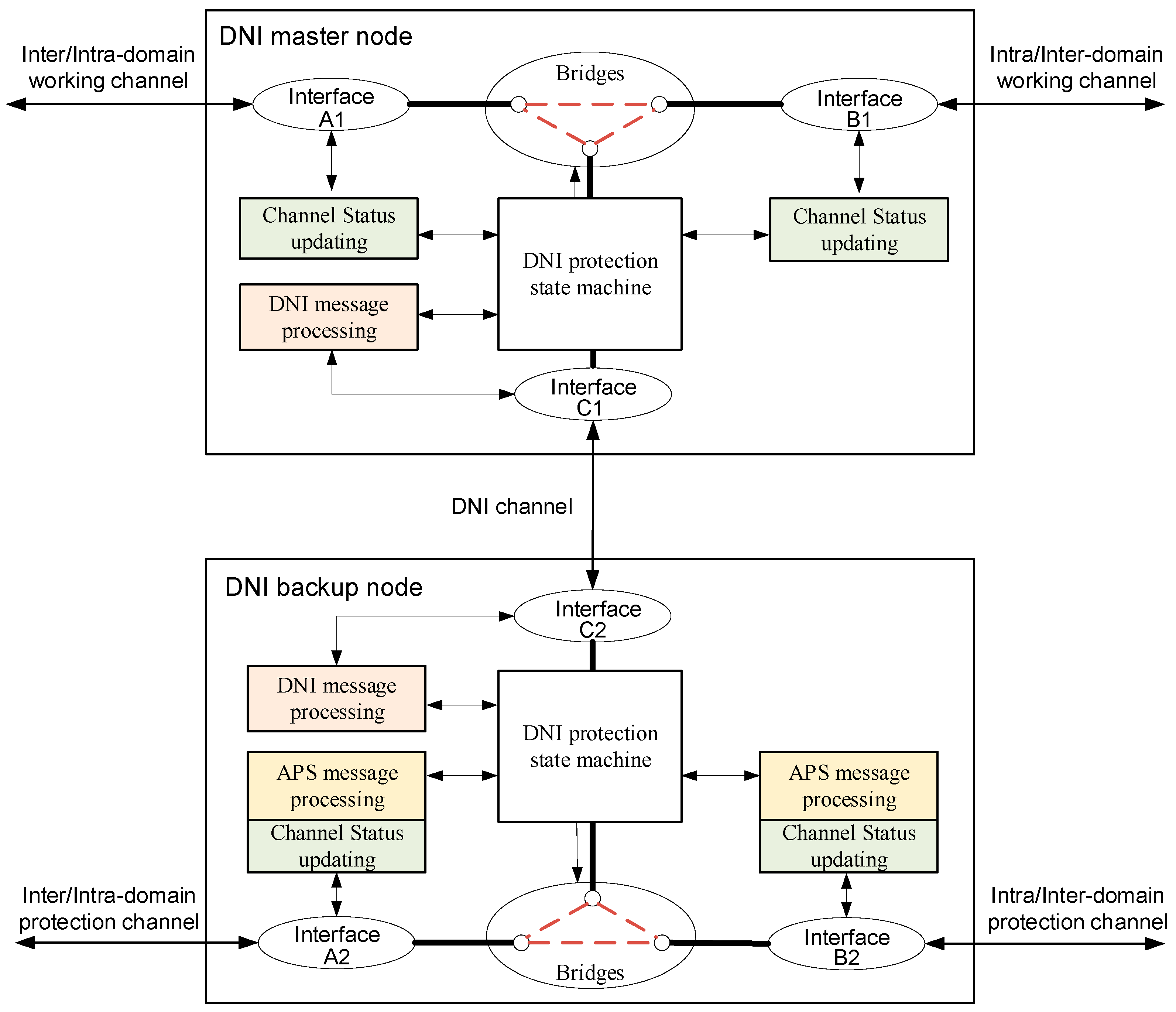
The DNI master node and the DNI backup node adopt a three-point bridge mechanism internally, as shown in
Figure 4. Take the master node as an example, the three access points of the intra/inter-domain working channel (A1), inter/intra-domain working channel (B1), and DNI channel (C1) are considered as three-point bridges. Unidirectional or bidirectional bridges are established between the three directions within the node as the output of the state machine based on the current state of the dual node and the conditions of the adjacent segments. This bridge mechanism provides a flexible bridge relationship between inter-domain and intra-domain.
Figure 4 also gives a functional diagram of a DNI node pair. The node functions include interfaces, protection bridge, channel status updating, DNI protection state machine, and DNI message processing. Besides, automatic protection switching (APS) message processing is specially configured in the DNI backup node. By utilizing the APS message, the fault status of both working and protection paths can be continuously monitored, which triggers timely switching in case of failures, and synchronizes the states of interconnected nodes [
28]. Therefore, incorporating APS message transmission on the protection channel is essential for maintaining robust and efficient network protection for the DNI protection scheme.
The channel failure or degradation state is perceived by channel status updating, and the channel switching state is obtained by APS message processing. Based on the channel status updating and the APS information, the channel cross-connection relationship is modified via the inside bridges in the pairs of master and backup dual nodes. The status of the channels on both sides of the node determines the outcome of the DNI protection state machine operation. The state machine decides the three-point bridge connection status of the DNI master node and the backup node, such as, whether interface A1 is bridged to B1 or to DNI channel interface C1.
3.3. Status Interaction Messages
To ensure effective protection switching, the DNI nodes must operate in a consistent and coordinated manner. Status interaction messages are configured segmentally on the working/protection channels and DNI channels, which play a critical role in enabling the proposed protection mechanism. The pair of DNI nodes periodically exchange DNI messages. The DNI message serves as a status notification to facilitate coordination between the master node and the backup node, conveying the associated channel status and the received messages. Once a change in fault conditions is detected via channel status updating, consecutive DNI messages should be sent immediately. The transmission interval of DNI messages is kept consistent with the APS message. The message consists of the following fields: Header, Channel Type Indicator, Failure State, APS State, and Switching State. Header is the initial field serving as the message identifier, containing essential information for message recognition and processing. Channel Type Indicator is a binary field that specifies whether the following state information belongs to the westbound-channel (represented by 0) or eastbound-channel (represented by 1). Failure State field indicates whether a failure has been detected through the channel status updating. APS State field carries the channel state information, which is vital for coordinating protection mechanisms between interconnected nodes. Switching State (active/standby) field serves as a control command that directs the DNI node interface to transition between active and standby modes, in which the active mode indicates to be working. This structured message format maintains clear distinction between different channel types and operational states.
DNI backup nodes run APS state machines for both intra-domain and inter-domain channels. The APS information supports not only protection switching functions triggered by fail events such as signal fail (SF), signal degrade (SD), and wait-to-restore (WTR), but also operator requests such as lockout of protection (LO), forced switch (FS) and manual switch (MS) commands [
28]. Prioritized protection between SF and operator requests should be supported.
3.4. Protection Switching Mechanism Example
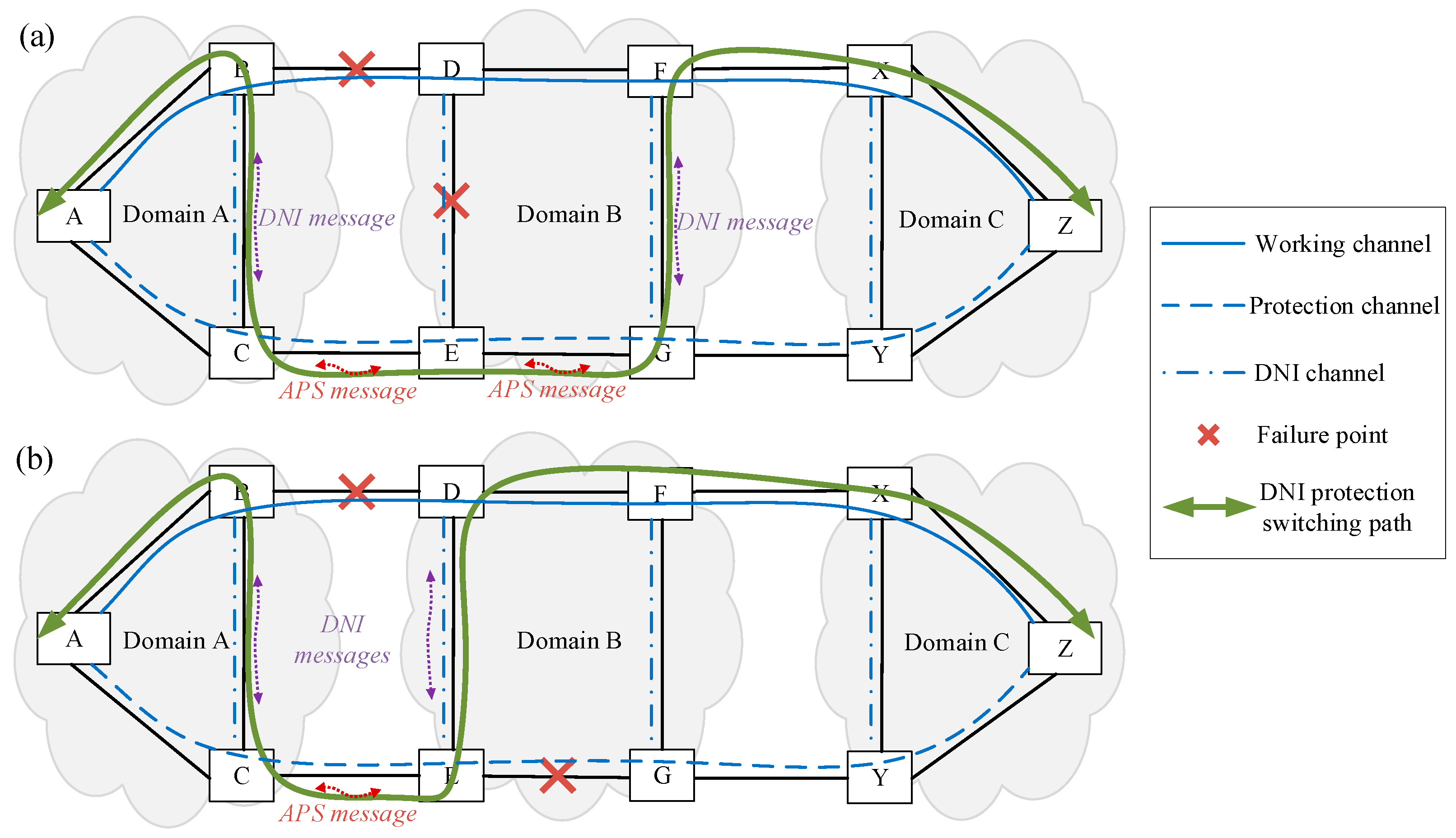
Figure 5 shows the DNI protection switching path in the scenarios of multipoint channel failures that traditional protection schemes cannot figure out.
Figure 5a depicts a case of intra-domain and inter-domain failures. Node B detects a fault on the inter-domain link between nodes B and D through channel status updating. Based on this information, the internal DNI protection state machine in node B determines the bridge relationship of its three interfaces, thereby bridging the path among node A, node B and node C. Node C perceives the channel fault status via the DNI message announced by node B and then transfer the APS message containing the fault conditions with switching state to the backup nodes (node E, node G). Node E senses the fault between nodes D and E by channel status updating. Combined with the received APS message, the protection state machine in node E then bridges the path among node C, node E and node G. Node G identifies the faults through APS information, then notifies node F of fault information and switching state via the DNI message. Upon receiving the DNI message, the protection state machine in node F connects the path among node G, node F and node X to establish the protection switching path.
As for the case in
Figure 5b, multiple failures occur on both working and protection paths in the intra-domain and inter-domain. In terms of the failure between nodes B and D, nodes B and C coordinate via the DNI message and execute a bridge relationship based on the three-point bridge mechanism, similar to nodes D and E. Nodes C and E exchange fault conditions and switching states by the APS message, enabling their protection state machines to establish the switching path B-C-E-D. So, the failure on the protection path between nodes E and G does not affect the protection switching outcome. The final DNI protection switching path, A-B-C-E-D-F-X-Z, reveals the domain-specific fault-handling capability. In contrast, traditional linear protection would trigger an end-to-end switchover to path A-C-E-G-Y-Z upon any working path failure. If the protection path also fails, service interruption occurs due to the lack of alternative connections.
3.5. Protection Performance Comparison
Considering the general deployment scenarios, the DNI-based cross-domain protection mechanism is compared to the traditional linear protection scheme, as ring configuration across multi-domain ring networks is quite complex and lacks practicality.
Table 1 comprehensively summarizes key aspects of the protection schemes, including interaction messages, path flexibility, fault isolation, and fault scenario coverage. By incorporating DNI messages and three-point bridge mechanism, the proposed approach maximizes path flexibility, enabling fault isolation and extending fault scenario coverage. These enhancements are particularly valuable in cross-domain scenarios in long-distance transmission, where reliability and resource efficiency are paramount. Relying on the message coordination between DNI nodes, this flexibility minimizes the need for extensive physical infrastructure changes, balancing the deployment costs and the protection performance. Besides, a common limitation of current protection schemes, including the proposed cross-domain technique, is the inability to handle simultaneous failures of both the working and protection paths. Diverse routing strategies could be explored to minimize the risk of simultaneous failures.
4. Field Trial
4.1. Setup
We experimentally validate the proposed cross-domain protection mechanism on the commercial multi-domain network in which the metro transport network (MTN) technologies are deployed. As defined in ITU-T G.8310 [
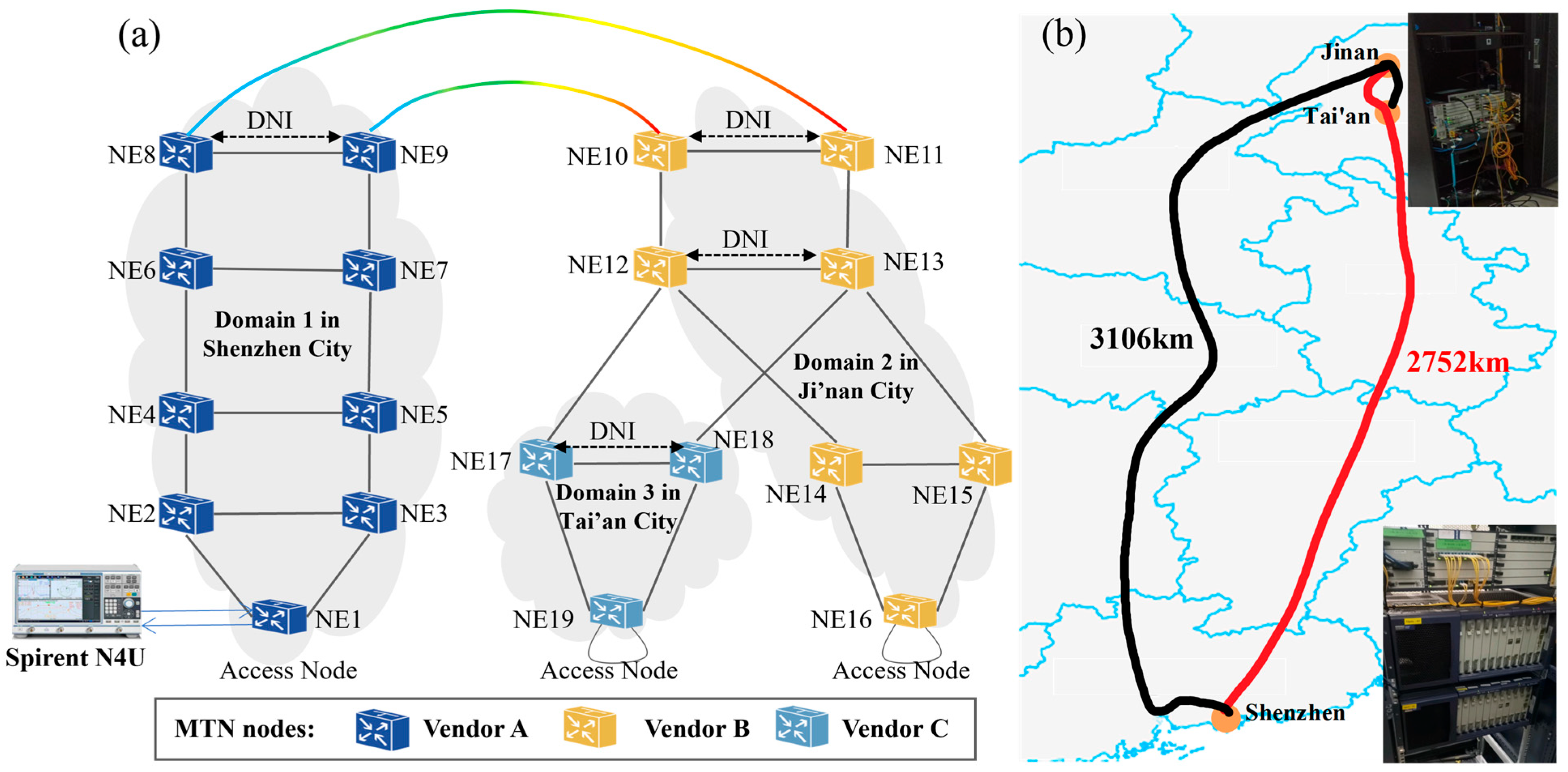
29], MTN has conceptualized a novel TDM technology tailored for Ethernet. It introduces TDM protocols to ensure telecommunication-grade service guarantees, such as physical isolation, high reliability and low latency. The network topology for the field trial is shown in
Figure 6a. Nineteen MTN network elements (NEs) from three vendors (Huawei, ZTE, and FiberHome) are deployed across three cities, with MTN nodes in each city forming a distinct network domain. Therefore, the network contains three domains, domain 1 is in Shenzhen City, domain 2 is in Ji’nan City, and domain 3 is in Tai’an City. The edge nodes of domain 1 and domain 2 are connected by using two geographically separated OTN channels, thus constructing two long-distance paths. In each domain, the pair of nodes connecting to the adjacent domain is configured with the DNI protection technique.
During the tests, two bidirectional services, denoted Service1 (S1) and Service2 (S2), are established. The endpoints of S1 are NE1 and NE16, and those of S2 are NE1 and NE19. The forward path of S1, labeled S1-Forward, runs from NE1 to NE16, and its reverse path, labeled S1-Reverse, runs from NE16 to NE1. Similarly, the forward path of S2, labeled S2-Forward, runs from NE1 to NE19, and its reverse path, labeled S2-Reverse, runs from NE19 to NE1. The forward path and the reverse path execute the protection switching process independently. For each service, one working path entity and one protection path entity are configured. The route of the working path is set along the shorter path with 2752 km as indicated by the red line in
Figure 6b, and the route of the protection path is set along the longer path with 3106 km as shown by the black line.
The network analyzer Spirent N4U is used to generate S1 and S2 services and test the protection switching performance. It is connected to the user network interface (UNI) of the access node NE1 and generates Ethernet packets with a bandwidth of 6 Mbps, which occupies one TDM slot. At NE16 and NE19, each service port is configured in loopback mode by connecting the transmit port and receive port via fiber. Therefore, packets are looped back to NE1, enabling the network analyzer to simulate the round-trip transmission of actual service traffic and monitor the transmission and reception performance of the established services.
To verify the protection switching performance of the proposed protection technique, the multi-point fault scenario is constructed for S1 and S2. This scenario includes an inter-domain fault (Failure 1) and an intra-domain fault (Failure 2). To comprehensively validate the potential fault conditions in practical networks, each failure is manually constructed as both port failures and fiber link failures. During the test, failures are initially induced by disabling a port or disconnecting a fiber, and the service protection switching behavior is observed. After successful service switching, failure recovery is conducted by re-enabling the ports or reconnecting the fibers, and the service revertive switching behavior is monitored.
4.2. Protection Switching Results
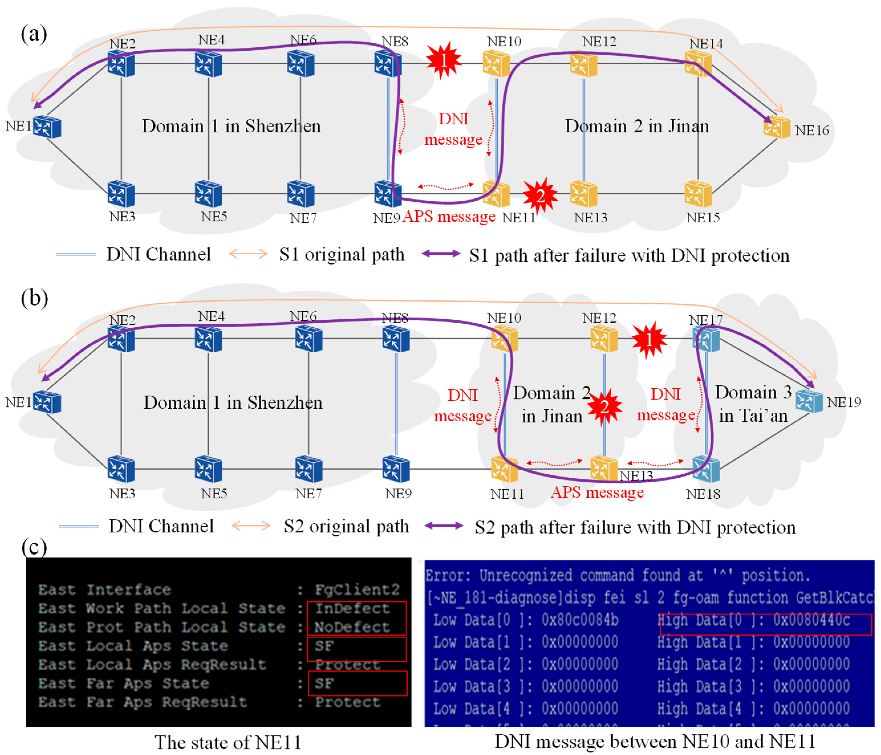
Figure 7 illustrates the protection switching results of service paths under the multi-point fault scenario for S1 and S2. For each service, the multi-point fault scenario is formed by two failure points labeled Failure 1 and Failure 2, respectively. Failure 1 is an inter-domain fault and Failure 2 is an intra-domain fault. Interaction messages captured in the test including the device state and the DNI message are also depicted.
Figure 7a demonstrates the protection switching test configuration for S1. Failure 1 occurs on the inter-domain working path between Shenzhen and Jinan, while Failure 2 occurs on the protection path in Jinan. When Failure 1 happens between NE8 and NE10 in Domain 1, NE8 and NE10 perceive the fault by channel status updating, and then the corresponding DNI messages and APS messages carry the fault condition and the switching state, enabling these four edge nodes coordinate to complete the protection switching process. The observed switching path is depicted by the purple curve compared to the original service path. The working link between NE10 and NE12 remains unaffected due to the DNI protection three-point bridge mechanism. Thus, when Failure 2 occurs in Domain 2, S1 remains uninterrupted because the failure does not affect the active working path, ensuring that the protection switching outcome remains unchanged. This demonstrates the domain-specific fault-handling capability of the protection mechanism, consistent with the analysis in
Section 3.4.
Figure 7b shows the multi-point failure test results for S2. Failure 1 occurs on the inter-domain connection between NE12 and NE17, and Failure 2 occurs within the Tai’an domain between NE12 and NE13. As shown in the protection switching path results in
Figure 7b, NE10 and NE11 perform protection switching despite no fault being directly detected on their adjacent links. This is due to the information exchange among DNI nodes, which notifies the far-end fault conditions and the switching state. As shown in
Figure 7c, the device status of NE11 can be queried via the network management command line, where the local path state is normal (no defect). The APS messages from NE13 indicate a signal failure (SF) on the remote working path between NE12 and NE17. Combined with the fault status of NE13, the local APS state of NE11 also transitions to SF and the switching status transfer from “standby” to “active”. Subsequently, NE11 announces the path failure status and the switching status to NE10 via the DNI message. The captured DNI messages at the device interface are shown in
Figure 7c, where “80” represents the message type of DNI message. The first “4” (binary: 0100) indicates the message sent by the backup node NE13, and the second “4” (binary: 0100) signifies an SF state, indicating a signal failure on the working path between NE10 and NE12 caused by Failure1 and Failure 2. The efficient interaction of DNI messages addresses the multi-point failure scenario for S2, ensuring reliable service continuity through coordinated switching actions.
After successful service protection switching, failure recovery is performed for each fault in the multi-point failure scenario. The high-precision sampling capability of Spirent N4U enables monitoring of the received signal rate throughout the entire process, from the protection switching triggered by the fault to the service revertive switching after fault recovery.
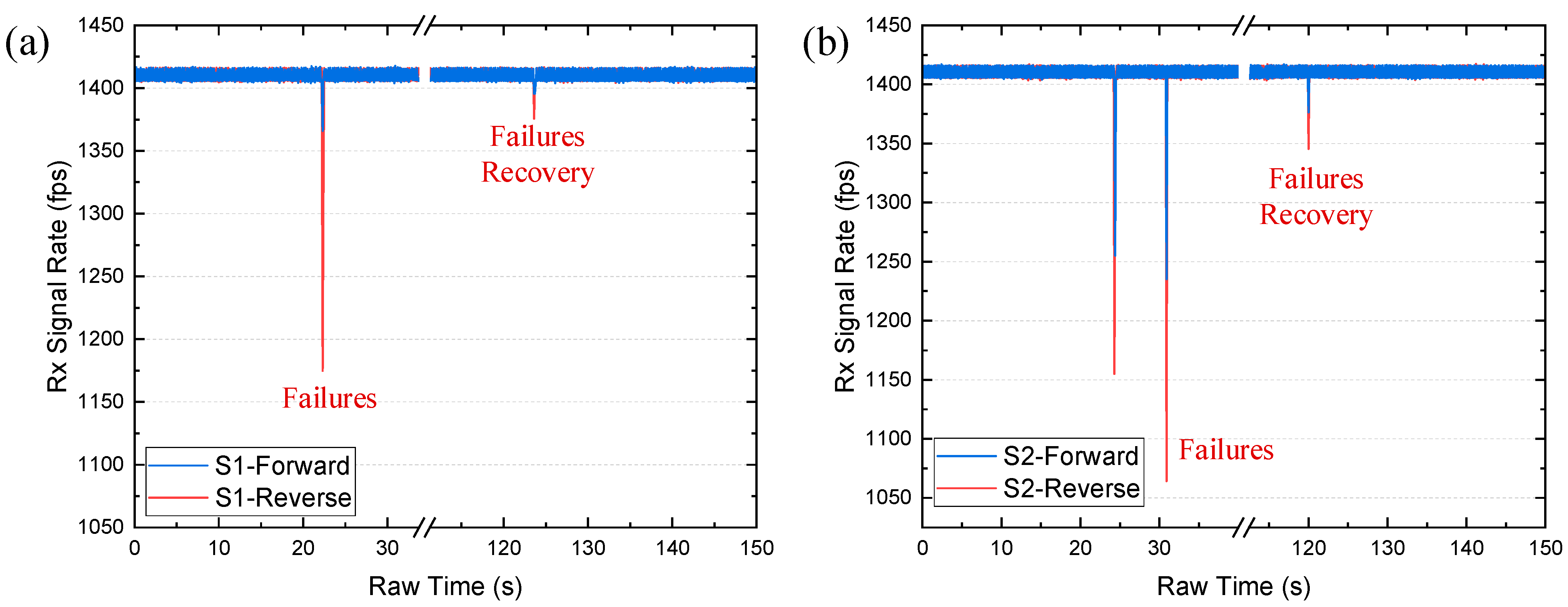
Figure 8 captures the entire process from fault occurrence to recovery for S1 and S2. The service is configured with a frame length of 512 bytes, a frame interval of 20 bytes, and a generated signal rate of 6 Mbps, resulting in a signal transmission rate of 1409 frames per second. Path switching during both fault occurrence and recovery results in frame loss, affecting the received signal rate. As shown in
Figure 8, the received signal rate first decreases sharply and then rapidly returns to its normal level during both fault occurrence and recovery, demonstrating the efficiency and reliability of the DNI-based cross-domain protection mechanism in minimizing service disruption and ensuring fast restoration.
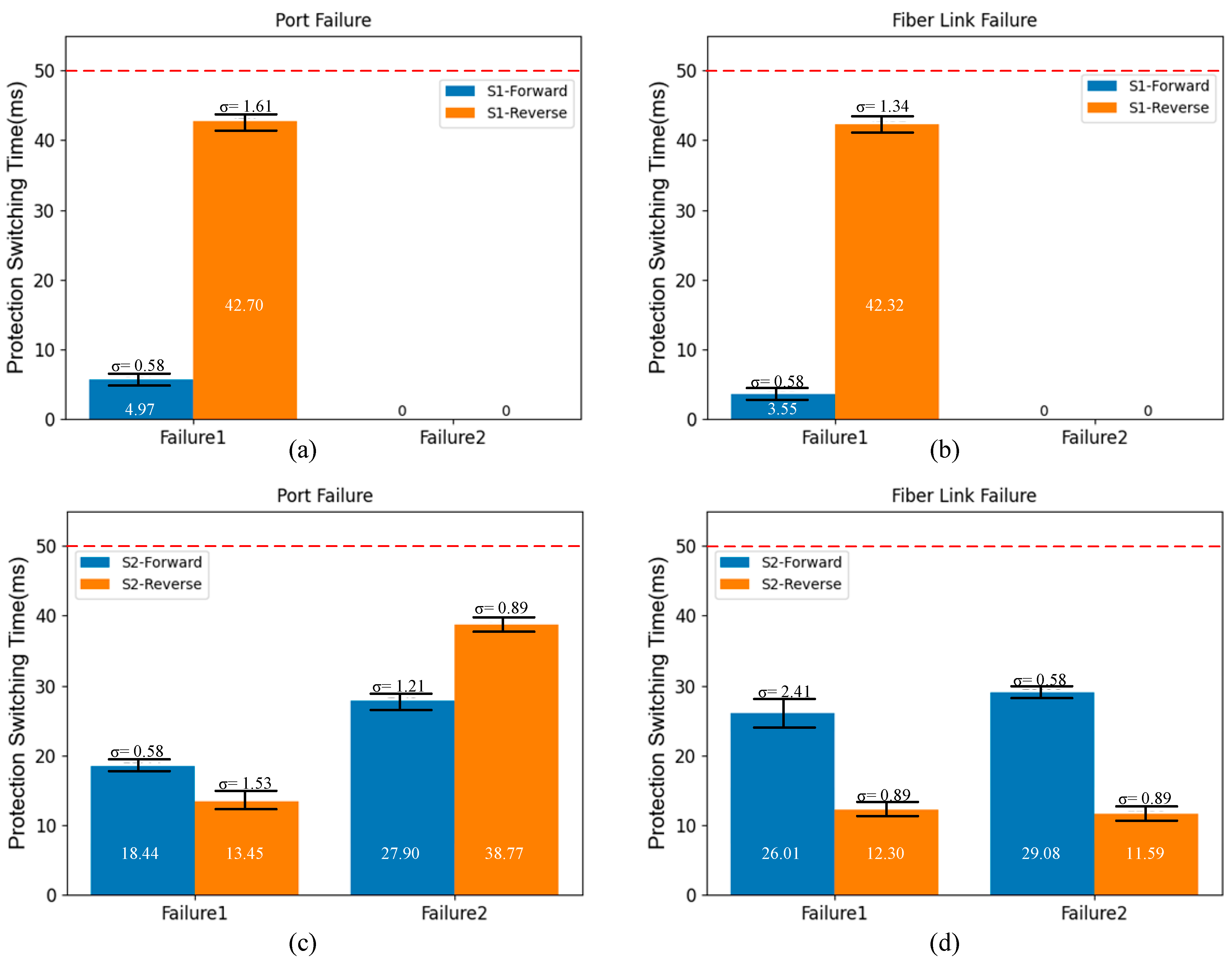
For the tests on S1 and S2, each failure in the multi-point failure scenario is manually constructed through port failures or fiber link failures. For each failure scenario, the protection switching is tested for three times. In terms of these two types of failures, the protection switching time in response to Failure 1 and Failure 2 is detailed in
Figure 9. The protection switching time is measured as the duration of signal frame loss from fault occurrence to the completion of switching, calculated based on the dropped frame count recorded by Spirent N4U.
Figure 9a,b depict the averaged frame loss duration for bidirectional S1 along with the standard deviations under port disablement and fiber link disruption, respectively, while
Figure 9c,d show the corresponding results for bidirectional S2. Taking the failures in
Figure 9b as an example, for Failure 1 on the forward path of S1, the maximum dropped frame count in the tests is 6, resulting in a frame loss duration of 4.26 ms at a transmission rate of 1409 frames per second. The reverse path of S1 experiences a maximum dropped frame count of 61, corresponding to a frame loss duration of 43.27 ms. It can be noticed that, the two service directions have different protection switching trigger points, such as NE8 for S1-Forward and NE10 for S1-Reverse. It is difficult to ensure the receiving and sending directions of the same fiber disconnected at the same time at the millisecond-level for the asynchronous nature of fault triggering. So, the discrepancy in switching times between the forward and reverse paths is attributed to the inherent differences in the device behavior and the protection switching logic. Notably, Failure 2 on the protection path causes no service disruption, as S1 remains uninterrupted due to the failure not affecting the active working path after Failure 1 is triggered, leaving the protection switching outcome unchanged. Overall, across all tested failure scenarios, the protection switching time for DNI protection remains below 50 ms, satisfying the stringent requirements for carrier-grade reliability.
Through extensive testing in intra-domain and inter-domain multi-fault scenarios, the proposed DNI protection mechanism is validated to effectively achieve service protection switching through the coordination of DNI nodes. Additionally, the mechanism demonstrates high performance in protection switching time, consistently meeting the carrier-grade requirement of below 50 ms. The consistent performance across devices from three vendors further confirms its interoperability, proving that the unified DNI protection mechanism delivers reliable results regardless of the device vendor. These findings highlight the practical benefits of the proposed DNI solution in meeting carrier-grade performance requirements.


