Abstract
Vortex lasers have shown significant advantages in fields such as quantum communication and optical detection due to their unique optical field structure. In this manuscript, we present a watt-level nanosecond Laguerre–Gaussian vortex beam from an end-pumped bonded Nd:YAG/V:YAG laser, which was pumped by a ring-shaped beam shaped by an axicon focusing system. By solving the transfer matrix of the resonator and designing a corresponding pump beam shaping system, mode matching between the LG01 beam and the annular pump beam was effectively achieved. The conditions for exciting the LG01 mode were theoretically calculated, and experimental results verified that the pump power required to excite the LG01 vortex beam is approximately twice that for exciting the fundamental Gaussian mode. Stable output of nanosecond lasers in the LG01 mode was achieved, with an output power of 1.943 W, a highest repetition rate of 291.3 kHz, a pulse width of 3.3 ns, and beam quality factors of in the horizontal direction and in the vertical direction. The results have significant value for applications such as visible light communication and high-resolution laser imaging.
1. Introduction
The Laguerre–Gaussian (LG) mode beam carrying orbital angular momentum (OAM) is a type of beam with a helical structure of equal-phase surfaces [1]. Due to its unique optical field structure, it offers distinct advantages in fields such as quantum communication and optical sensing [2,3], making it a hot topic in optical research. With the rapid advancement of laser technology in the red visible light spectrum, vortex lasers in this wavelength range have attracted widespread attention [4]. Pulsed red lasers primarily rely on frequency doubling of lasers in other wavelength ranges, and 1319 nm is one of the main wavelengths for red laser frequency doubling. Therefore, researching the generation of a pulsed 1319 nm vortex beam can greatly promote applications in visible light communication, high-resolution laser imaging [5,6], and other fields, holding significant scientific value and practical importance.
The generation of vortex beams can be mainly classified into two categories: external generation and direct generation within the resonator [7,8]. External generation methods include using spiral phase plates [9], and spatial light modulators [10], to convert the fundamental Gaussian beam into a vortex beam. However, external generation methods generally require additional components and suffer from issues such as low efficiency, poor mode purity of the generated vortex beam, and unstable transmission. Direct generation of vortex beam within the resonator is achieved by actively selecting the oscillating laser mode [11,12,13], which makes the laser more compact and more efficient. Among these methods, annular pumping is used as it can control the mode matching with the LG beam, thus enabling the output of specific vortex beams [14]. Currently, an annular pump beam is mostly generated using custom-made optical fibers [15], which are only applicable to specific lasers. However, the design, fabrication, and use of special optical fibers are not straightforward and are contrary to the simple nature of annular beam pumping, increasing the difficulty of system construction. Some researchers have also used point defects or optical path designs to eliminate the central beam of the pump beam to generate an annular beam [16]. In most cases, the pump beam for shaping into an annular beam is a Gaussian beam; however, the energy of a Gaussian beam is concentrated in the center, and using the above methods wastes a large portion of the energy, resulting in a low energy conversion efficiency. In this manuscript, an axicon focusing system was used to reshape the pump beam into a ring-shaped beam, which then directly pumped the bonded Nd:YAG/V:YAG crystal to output the vortex hollow beam. This method can generate annular pump beams with a radius on the order of hundreds of micrometers, and the radius of the ring-shaped hollow beam can be conveniently controlled, achieving good mode matching with the oscillation mode of the laser. Moreover, axicons are already well-developed in commercial products, and using them to generate annular beams makes the overall structure simpler and easier to integrate.
Currently, 1319 nm lasers are typically generated by using Nd:YAG crystals for solid-state lasers. In 2015, Wang Zhaowei et al. reported a pulsed laser diode end-pumped Nd:YAG/V:YAG passive Q-switched 1319 nm laser [17]. When the absorbed pump pulse energy was 21.9 mJ, the maximum output pulse energy was 3.3 mJ, the shortest pulse width was 6.16 ns, and the peak power was 64.9 kW. In 2022, Bian Qi et al. reported a single-wavelength 1319 nm Nd:YAG laser [18], which used a birefringent plate to suppress the adjacent 1338 nm spectral line, achieving single-wavelength oscillation at 1319 nm with an average power of 51.5 W, pulse width of 154 ns, maximum peak power of 0.655 MW, and pulse energy of 81.2 mJ. By using annular beam pumping on Nd:YAG crystals, LG beam output can be achieved. In 2023, Yashuai Yang et al. reported an intracavity cascade pumping structure and annular beam end-pumped Nd:YAG crystals [19], obtaining 946/1030 nm dual-wavelength LG01 mode vortex laser output.
In this manuscript, the threshold pump power for generating a vortex beam in a resonator was theoretically calculated, and the relationship between the pump power for generating the first-order LG mode and the pump power for generating the Gaussian fundamental mode was derived; the pump power required to excite the LG01 vortex beam is approximately twice that for exciting the Gaussian fundamental mode. An axicon focusing system was designed to reshape the fiber-coupled LD pump beam into a ring-shaped beam, and pumped a bonded Nd:YAG/V:YAG crystal, a 1319 nm LG beam output with a maximum output power of 1.943 W, a maximum repetition rate of 291.3 kHz, a pulse width of 3.3 ns, an optical-to-optical conversion efficiency of 10.5%, and a slope efficiency of 16% was achieved.
2. Theoretical Analysis
The annular pumping method has unique advantages in generating vortex hollow beams for LD-pumped solid-state lasers. The annular pumping method is essentially a transverse mode selection technique, commonly used in the field of lasers to obtain high beam quality fundamental Gaussian beams. This technique can also be used to suppress the oscillation of the fundamental Gaussian beam to achieve higher-order transverse mode output. The principle of transverse mode selection is based on the fact that different transverse modes in the resonator have different gains and losses. By compensating the single-pass gain of the target mode to offset its single-pass loss, while the single-pass gain of other modes cannot compensate for their single-pass loss, the desired mode can be selected. According to the mode matching theory, to achieve the output of an LG vortex beam, the intensity distribution of the pump beam should match that of the desired mode. The pump beam only needs to match the intensity distribution, without requiring any other phase characteristics. Therefore, the expression for the pump beam can be simplified as
In the above equation, ω1 represents the radius of the outer annular of the pump beam, ω2 represents the radius of the inner annular of the pump beam, and m is the normalization factor.
The rate equation of the laser in a steady state is given by
In the above equations, N(x, y, z) represents the population inversion density distribution function, R(x, y, z) represents the pumping rate, Si(x, y, z) represents the photon number density in various modes, τ represents the fluorescence lifetime of the gain medium, σ represents the emission cross-section of the gain medium, γi represents the loss factor, si represents the photon number for different modes, Lc,i represents the intracavity round-trip loss, and d represents the cavity length. It is assumed that for the output of any mode, N(x, y, z) and Si(x, y, z) are the same and satisfy
Here, S0i(x, y, z) and R0(x, y, z) are the normalization functions, vp represents the pump beam frequency, η represents the absorption efficiency, h is Planck’s constant, and Pin represents the pump power. The oscillation power threshold for the fundamental Gaussian beam in the resonator can be derived as
Similarly, the oscillation power threshold for the first-order LG vortex beam in the resonator can be derived as
By comparing Equations (10) and (11), it can be seen that the main difference in the power threshold required to generate different modes lies in the mode intensity distribution and the pump intensity distribution. The normalized intensity of a Laguerre–Gaussian beam can be obtained by taking the square modulus of its electric field expression. Since the phase factor exp(imφ) and the propagation-related term vanish in the modulus square, the normalized intensity S0,m(x, y, z) is determined solely by the amplitude component.
Similarly, treating R0(x, y, z) as a Gaussian-type function, according to Equations (10)–(12), the ratio β of the threshold power for generating the first-order LG mode to that for generating the Gaussian fundamental mode in the same resonator is given by
By substituting the relevant values into Equation (13), it is calculated that β ≈ 2. This indicates that the pump power required to generate the first-order LG mode in the resonator via annular beam pumping is approximately twice the power required to generate the Gaussian fundamental mode. This establishes a solid theoretical foundation for the adjustment of pump power in subsequent experiments.
To achieve a matching intensity distribution between the annular pump beam and the LG oscillating beam in the resonator, it is first necessary to determine the beam spot size of the oscillating beam in the resonator. In this study, the coatings on both ends of the gain crystal serve as the cavity’s total reflection mirror and output coupling mirror, forming a plane–plane resonator, as shown in Figure 1. Let M1 and M2 denote the two cavity mirrors. Considering the thermal lens effect, the crystal is regarded as consisting of an equivalent thermal lens and the remaining part excluding the thermal lens. The distance between M1 and the thermal lens is L1, and the distance between M2 and the thermal lens is L2. The length of the crystal is L0, n is the refractive index of the crystal, f is the focal length of the equivalent thermal lens, and 1/2n is the central thickness of the equivalent thermal lens.
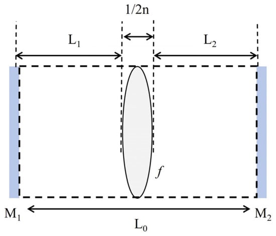
Figure 1.
Schematic diagram of the 1319 nm laser resonator.
By calculation, the beam spot radius of the Gaussian beam at the corresponding plane can be obtained as
Due to the use of bonded crystals, the end facets of the crystals are coated as resonator mirrors. The relevant parameters can be simplified as . When the thermal lens focal length f = 1020 mm, which corresponds to the pump power, the round-trip matrix at the principal plane of the end of the crystal-coated high reflective film is obtained as
By substituting the data, the total matrix Mtot is obtained as . Substituting into Equation (14), the spot radius of the oscillating fundamental mode is obtained as .
The spot radius of the LG beam can be expressed as
In the above equation, is the spot radius of the fundamental Gaussian beam, and l is the order of the LG beam. Therefore, the spot radius of the first-order LG beam in the resonator is approximately 201.2 μm.
3. Experimental Design
In order to match the pump beam intensity distribution with that of the LG beam, an axicon focusing system was used to shape the pump beam into a ring-shaped beam, which then pumped a bonded Nd:YAG/V:YAG crystal, and a vortex hollow beam was obtained. This method can generate annular beams with a radius of hundreds of micrometers, and the size can be easily adjusted, allowing for a good mode matching with the oscillation mode of the laser.
An axicon focusing system consisting of a plano-convex lens with a focal length of 25.4 mm and curvature radius of 13.1 mm, and an axicon with a cone angle of 20°, was used to shape the pump beam, and the beam intensity distribution was simulated by Zemax. The system structure is shown in Figure 2. Here, “Lens” refers to a plano-convex lens, “Axicon” refers to a conical lens with a cone angle of 20°, “R” represents the radius of the incident parallel light, and “d” represents the distance to the cone angle of the axicon lens. For the axicon focusing system with parallel light incidence, the beam intensity distribution can be derived based on the Huygens–Fresnel diffraction integral theory. Within the diffraction-free distance, the spot cross-section intensity follows a Bessel function distribution.
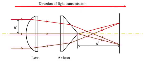
Figure 2.
Structural diagram of the axicon focusing system with a 20° apex angle, the red solid line in the diagram represents the optical propagation path, and the yellow dashed line represents the optical axis of the axicon focusing system.
A fiber-coupled 808 nm LD was used as the pump source, with a core diameter of 200 μm and a numerical aperture of 0.22. A plano-convex lens was used to collimate the output beam of fiber, and the distance between the plano-convex lens and the axicon was adjusted to simulate the spot distribution of the hollow beam. The spot incoherent irradiance cross-section distribution corresponding to a defocus spot radius of 1 mm was selected for comparative analysis, as shown in Figure 3. In the simulation, the distance between the two lenses varied from 2 mm to 8 mm, and the incoherent irradiance cross-section distributions were analyzed for the defocus spot radius of 1 mm.
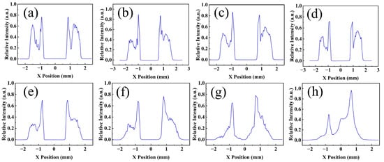
Figure 3.
Comparison of the cross-sectional distribution of incoherent irradiance for different lens separations (Δ d = 1–8 mm) when the diffuse spot radius is 1 mm, where (a) corresponds to Δ d = 1 mm, (b) to Δ d = 2 mm, (c) to Δ d = 3 mm, (d) to Δ d = 4 mm, (e) to Δ d = 5 mm, (f) to Δ d = 6 mm, (g) to Δ d = 7 mm, and (h) to Δ d = 8 mm.
The simulation showed that as the distance between the plano-convex lens and the axicon decreases, the hollow beam distribution becomes more uniform, and the hollow region becomes larger. Therefore, the plano-convex lens and the axicon should be placed as close as possible to each other.
The spot radius was calculated using the irradiance curve from geometric image analysis under sequential mode, as shown in Figure 4. By performing an integral calculation, when the irradiance reaches 86.5% of the total beam irradiance, the corresponding value of the x-coordinate represents the outer radius of the ring-shaped spot at that position.
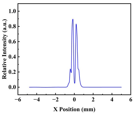
Figure 4.
The diagram of irradiance distribution.
Table 1 shows the corresponding pump beam spot radii calculated from the irradiance map at different distances from the focus of the axicon system. It can be seen that the spot radius variation range meets the mode-matching requirements for the first-order LG mode.

Table 1.
Spot sizes at different locations.
A bonded Nd:YAG/V:YAG crystal was used to generate a pulsed LG vortex laser, and two facets were coated to serve as the high-reflection mirror and the output coupler, respectively, forming a plane–plane resonator, as shown in Figure 5. The overall dimension of the bonded crystal was 3 mm × 3 mm × 5.5 mm. The Nd:YAG crystal had a doping concentration of 1 at.%. The pump beam incident surface was coated with high-transmission coating for 808 nm, 1064 nm, and 946 nm (T > 97%), as well as a high-reflection coating for 1319 nm (R > 99%) to serve as the high-reflection mirror for the laser resonator. The V:YAG crystal served as a saturable absorber. By controlling the intracavity gain, nanosecond pulse laser output was achieved, with the crystal end face acting as the output coupler of the laser resonator. It was coated with high-transmission coating for 1064 nm and 946 nm (T > 97%), with a transmission of T > 60% for 1338 nm and an output transmission of T = 10% for 1319 nm.
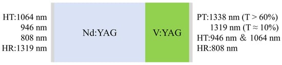
Figure 5.
Schematic diagram of the compact 1319 nm resonator structure.
The experimental setup of the annular pumped bonded Nd:YAG/V:YAG laser is shown in Figure 6, consisting of a fiber-coupled LD module (105 µm fiber core and 0.22 NA), collimating lens (f = 30 mm), axicon group (Thorlabs AX2520-B, n = 1.45, = 20°), and bonded Nd:YAG/V:YAG crystal. The entire structure is simple and compact.
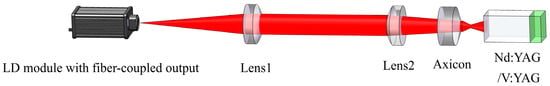
Figure 6.
Experimental setup of annular pumped bonded Nd:YAG/V:YAG laser.
4. Results and Discussion
The axicon focusing system was used to shape the collimated pump beam, and the distribution uniformity of the shaped pump beam spot at different distances from the ax-icon apex was measured by CCD (Thorlabs BC106N, Thorlabs, Newton, NJ, USA), as shown in Figure 7. It can be seen that the axicon focusing system effectively shapes the Gaussian beam into a ring-shaped beam. At distances of d = 5, 7, and 10 mm from the apex of the conical lens, the radii of the light spots were 1.92, 2.64, and 3.77 mm, and the resulting ring-shaped beam has a uniform distribution with a distinct hollow region.
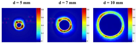
Figure 7.
Distributions of the ring-shaped beam at different distances d from the axicon apex. (d = 5, 7, 10 mm).
The power of the reshaped light spot was measured using a power meter, as shown in Figure 8. The pump source exhibited negligible power loss after passing through the collimating lens. However, due to the influence of the conical prism in the conical lens assembly, the power slightly decreased. At a current of 8 A, a pump light output of 45 W was achieved. Through calculation, it was determined that the output optical power of the pump source experienced a total loss of 5.41% after passing through the entire beam shaping system. This indicates that the conical lens assembly can effectively reshape a Gaussian beam into a ring-shaped beam with low power loss.
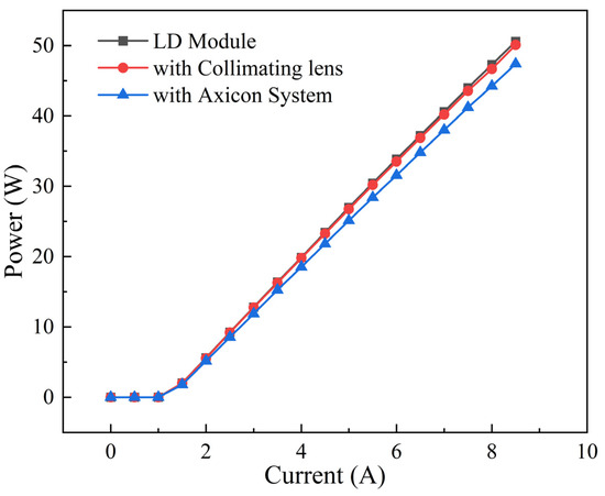
Figure 8.
Power attenuation of the 808 nm pump beam after shaping.
When the pump power reached 4.92 W, the fundamental mode of the resonator began to oscillate, and the output laser exhibited a Gaussian intensity distribution in a circular spot, as shown in Figure 9a. Increasing the pump power to 10.69 W, the output laser transitioned to a hollow-ring LG mode, with the threshold power for the LG mode approximately twice that of the fundamental Gaussian mode. By adjusting the focus of the axicon system at different positions within the crystal, the corresponding pump powers for exciting the fundamental Gaussian mode and the LG01 mode were measured. From Figure 9b, it can be observed that the pump power for exciting the fundamental Gaussian mode and the LG01 mode also satisfies the relationship where the pump power for the LG01 mode is twice that of the fundamental Gaussian mode threshold power.
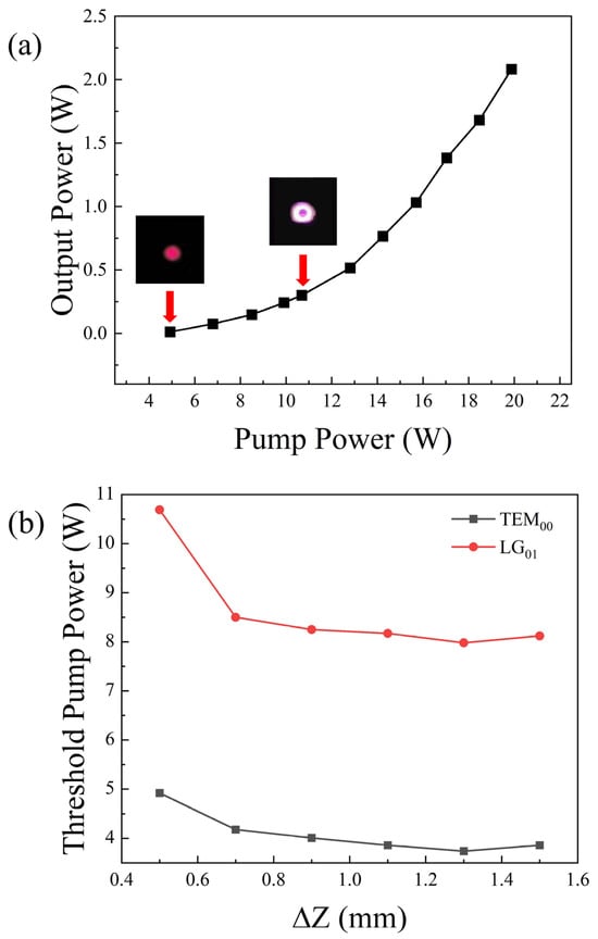
Figure 9.
(a) Relationship between the 1319 nm laser output power and pump power. (b) Relationship between pump power for fundamental mode and LG mode at different focus positions within the crystal.
To detect the generated ring-shaped beam, a Mach–Zehnder interferometer method was used to produce cross-shaped interference fringes by interfering with the vortex beam with a plane wave, allowing for the topological charge of the vortex beam to be detected. Its structure is shown in Figure 10a. The output laser was split by a beam splitter into transmitted and reflected beams. The beam splitter was an energy-type semi-transparent mirror. The transmitted beam passed through a plano-convex lens with a focal length of 25.4 mm and another plano-convex lens with a focal length of 75 mm for shaping; then, after passing through the second total reflector Mirror 2, the beam entered the combiner (the combiner and the beam splitter were identical). The other beam, after passing through the first total reflector Mirror 1, also entered the combiner, where it was combined with the shaped beam, resulting in an interference phenomenon.
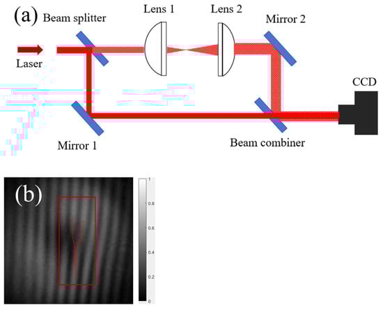
Figure 10.
(a) Principle diagram of topology charge detection using the MZ interference method. (b) Interference generating fork-shaped fringes.
The interference pattern is shown in Figure 10b. It can be seen that clear fork-shaped fringes appear in the center of the interference pattern, with the open end of the cross facing upwards. This indicated that the topological charge of the oscillating beam was 1, confirming that the oscillating laser was a first-order LG beam.
The output optical characteristics were characterized using a spectrometer (Yokogawa AQ6375, Yokogawa Electric Corporation, Tokyo, Japan) to measure the laser spectrum of the laser output. As shown in Figure 11, the center wavelength of the output laser was observed to be 1319 nm at an input current of 4 A.
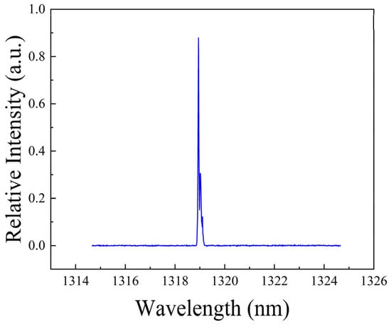
Figure 11.
Output spectrum of the 1319 nm vortex laser.
The beam quality of the output laser was measured. A lens with a focal length of 150 mm was used to focus the output laser, the experimental setup is illustrated in Figure 12, and the spot size was measured at different positions in front and behind the focal point. The data obtained were fitted with a hyperbola using ORIGIN 2021 v9.8.0 software (Northampton, MA, USA), as shown in Figure 13. The beam quality of the output laser was calculated from the following hyperbolic fitting parameters: .
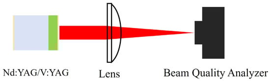
Figure 12.
Schematic diagram of experimental setup for measuring the spot size of a 1319 nm vortex beam.
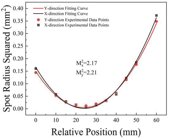
Figure 13.
Beam quality of the 1319 nm laser.
For the LG beam, the beam quality factor expression is . Thus, the beam quality factor M2 of the first-order LG01 mode is greater than or equal to 2, and the closer it is to 2, the better the beam quality. This indicates that the beam quality in the x-direction is better than in the y-direction. This also confirms that the oscillated beam is an LG01 beam, and its overall beam quality is good.
An oscilloscope (Rigol DHO4804, RIGOL Technologies Co., Ltd., Beijing, China) was used to measure the pulse waveform. Figure 14 shows the Q-switched pulse sequence, with a measured highest repetition frequency of 290.3 kHz, the minimum time interval between adjacent pulses was 3.43 μs, the maximum was 5.45 μs, and the variance was 0.57. The shortest pulse width was 3.3 ns, the single pulse energy measured by the energy meter was 6 μJ, and the energy instability was calculated to be 3.2%. The method for calculating energy instability involved sampling the energy over a period of time, calculating the standard deviation and the mean value, and then determining the ratio of the standard deviation to the mean value, which represented the energy instability.
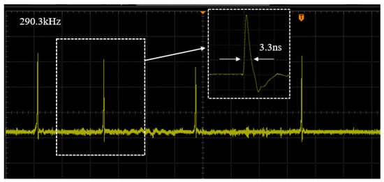
Figure 14.
Frequency diagram of the 1319 nm laser.
5. Conclusions
In conclusion, the conditions required to excite the LG01 mode were theoretically calculated, and the relationship of threshold pump power was experimentally demonstrated, which was that the pump power for exciting the LG01 vortex beam is approximately twice that of the pump power required for exciting the fundamental Gaussian mode. An axicon focusing system was designed to reshape the fiber-coupled LD pump beam into a ring-shaped beam and pumped a bonded Nd:YAG/V:YAG crystal, and a stable output of nanosecond lasers in the LG01 mode was obtained. The output power of the vortex laser was 1.943 W, with an optical-to-optical conversion efficiency of 10.5%, a slope efficiency of 16%, and a measured center wavelength of 1319 nm. The beam quality factors were in the horizontal direction and in the vertical direction, the highest repetition rate measured was 291.3 kHz, and the pulse width was 3.3 ns. The generation of a 1319 nm vortex beam can significantly advance applications in visible light communication, high-resolution laser imaging, and other fields, offering considerable scientific value and practical significance.
Author Contributions
Conceptualization, S.Y. and S.C.; methodology, S.Y., S.C. and M.J.; software, S.Y. and S.C.; validation, S.C.; formal analysis, Y.L.; investigation, S.C.; resources, W.Q., Y.C. and Z.W.; data curation, S.Y. and S.C.; writing—original draft preparation, S.Y. and S.C.; writing—review and editing, M.J.; visualization, S.Y. and S.C.; supervision, M.J.; project administration, M.J.; funding acquisition, M.J. All authors have read and agreed to the published version of the manuscript.
Funding
Beijing Natural Science Foundation (No. L241061).
Institutional Review Board Statement
Not applicable.
Informed Consent Statement
Not applicable.
Data Availability Statement
Data underlying the results presented in this manuscript are not publicly available at this time but may be obtained from the authors upon reasonable request.
Conflicts of Interest
The authors declare no conflicts of interest.
References
- Allen, L.; Beijersbergen, M.W.; Spreeuw, R.J.C.; Woerdman, J.P. Orbital angular momentum of light and the transformation of Laguerre-Gaussian laser modes. Phys. Rev. A At. Mol. Opt. Phys. 1992, 45, 8185–8189. [Google Scholar] [CrossRef] [PubMed]
- Shen, Y.; Wang, X.; Xie, Z.; Min, C.; Fu, X.; Liu, Q.; Gong, M.; Yuan, X. Optical vortices 30 years on: OAM manipulation from topological charge to multiple singularities. Light Sci. Appl. 2019, 8, 90. [Google Scholar] [CrossRef] [PubMed]
- Shen, D.; He, T.; Yu, X.; Zhao, D. Mode Conversion and Transfer of Orbital Angular Momentum Between Hermite-Gaussian and Laguerre-Gaussian Beams. IEEE Photonics J. 2022, 14, 1–6. [Google Scholar] [CrossRef]
- Wei, M.D.; Lai, Y.S.; Chang, K.C. Generation of a radially polarized laser beam in a single microchip Nd:YVO4 laser. Opt. Lett. 2013, 38, 2443–2445. [Google Scholar] [CrossRef] [PubMed]
- Ma, Y.; Tung, J.; Chen, Y.; Miyamoto, K.; Omatsu, T. Direct generation of visible vortex beams from a diode-pumped Pr3+:YLF laser. JSAP Annu. Meet. Ext. Abstr. 2019, 698. [Google Scholar] [CrossRef]
- Nikolić, M.; Scarcelli, G. Long-term Brillouin imaging of live cells with reduced absorption-mediated damage at 660nm wavelength. Biomed. Opt. Express 2019, 10, 1567–1580. [Google Scholar] [CrossRef] [PubMed]
- Fang, Z.; Yao, Y.; Xia, K.; Li, J. Simple Nd:YAG laser generates vector and vortex beam. Chin. Opt. Lett. 2015, 13, 51–54. [Google Scholar] [CrossRef]
- Apurv Chaitanya, N.; Chaitanya Kumar, S.; Devi, K.; Samanta, G.K.; Ebrahim-Zadeh, M. Ultrafast optical vortex beam generation in the ultraviolet. Opt. Lett. 2016, 41, 2715–2718. [Google Scholar] [CrossRef] [PubMed]
- Zhou, J.; Lin, P.T. Efficient mid-Infrared vortex beam generation using optical waveguides integrated with micro-spiral phase plates. J. Opt. 2019, 21, 105801. [Google Scholar] [CrossRef]
- Szatkowski, M.; Masajada, J.; Augustyniak, I.; Nowacka, K. Generation of composite vortex beams by independent Spatial Light Modulator pixel addressing. Opt. Commun. 2020, 463, 125341. [Google Scholar] [CrossRef]
- Qiao, Z.; Xie, G.; Wu, Y.; Yuan, P.; Ma, J.; Qian, L.; Fan, D. Generating High-Charge Optical Vortices Directly from Laser Up to 288th Order. Laser Photonics Rev. 2018, 12, 1800019. [Google Scholar] [CrossRef]
- Liu, Q.; Zhao, Y.; Ding, M.; Yao, W.; Fan, X.; Shen, D. Wavelength- and OAM-tunable vortex laser with a reflective volume Bragg grating. Opt. Express 2017, 25, 23312–23319. [Google Scholar] [CrossRef] [PubMed]
- Thirugnanasambandam, M.P.; Senatsky, Y.; Ueda, K. Generation of very-high order Laguerre-Gaussian modes in Yb:YAG ceramic laser. Laser Phys. Lett. 2010, 7, 637–643. [Google Scholar] [CrossRef]
- Yang, Q.; Yang, Z.; Cai, D.; Ren, X.; Li, C.; Zu, Y.; Ud Din, S.Z.; Leng, J.; Liu, J.; He, J. Direct generation of continuous-wave and passively Q-switched visible vortex beams from a doughnut-shaped diode-pumped Pr:YLF laser. Opt. Express 2022, 30, 23909–23917. [Google Scholar] [CrossRef] [PubMed]
- Kim, J.W.; Clarkson, W.A. Selective generation of Laguerre–Gaussian (LG0n) mode output in a diode-laser pumped Nd:YAG laser. Opt. Commun. 2013, 296, 109–112. [Google Scholar] [CrossRef]
- Tong, L.; Yuan, Y.; Zhang, W.; Chen, C.; Cai, Y.; Zhao, L. High-power picosecond structured optical vortices directly generated in an all-solid-state laser. Opt. Laser Technol. 2022, 155, 108396. [Google Scholar] [CrossRef]
- Wang, Z.; Zhang, B.; Ning, J.; Zhang, X.; Su, X.; Zhao, R. High-peak-power passively Q-switched 1.3 μm Nd:YAG/V3+:YAG laser pumped by a pulsed laser diode. Chin. Opt. Lett. 2015, 13, 53–56. [Google Scholar] [CrossRef]
- Bian, Q.; Bo, Y.; Zuo, J.W.; Peng, Q.J. High Pulse Energy 1319 nm Q-Switched Nd: YAG Laser. IEEE J. Quantum Electron. 2022, 58, 1–4. [Google Scholar] [CrossRef]
- Yang, Y.; Li, Y.; Wang, C.; Yang, C. 946/1030 nm Dual-Wavelength Laguerre-Gaussian (LG01) Mode Vortex Laser Based on Intracavity Cascade Pumped Resonator. Photonics 2023, 10, 441. [Google Scholar] [CrossRef]
Disclaimer/Publisher’s Note: The statements, opinions and data contained in all publications are solely those of the individual author(s) and contributor(s) and not of MDPI and/or the editor(s). MDPI and/or the editor(s) disclaim responsibility for any injury to people or property resulting from any ideas, methods, instructions or products referred to in the content. |
© 2025 by the authors. Licensee MDPI, Basel, Switzerland. This article is an open access article distributed under the terms and conditions of the Creative Commons Attribution (CC BY) license (https://creativecommons.org/licenses/by/4.0/).