Article

Coherent Perfect Absorption in a Parametric Cavity-Ensemble System

Department of Physics, Wenzhou University, Wenzhou 325035, China
*
Authors to whom correspondence should be addressed.
Photonics 2025, 12(11), 1135; https://doi.org/10.3390/photonics12111135
Submission received: 18 October 2025 / Revised: 12 November 2025 / Accepted: 13 November 2025 / Published: 17 November 2025
(This article belongs to the Special Issue Quantum Optics: Communication, Sensing, Computing, and Simulation)

Abstract

We propose a scheme to achieve CPA not only in the strong-coupling regime but also in the weak-coupling regime. The system under consideration consists of an atomic ensemble coupled to an optical cavity containing an optical parametric amplifier (OPA). We show that when the OPA introduces an effective loss, CPA can occur only in the strong-coupling regime. In contrast, when the OPA provides an effective gain, CPA can emerge in both the weak- and strong-coupling regimes. We further demonstrate that in the weak-coupling regime, CPA cannot occur within the bistable region, whereas in the strong-coupling regime, CPA can indeed appear in the bistable region. Moreover, the output intensity can be flexibly controlled by tuning the effective strength and the phase of the OPA. Our work opens a potential way to design a coherent perfect absorber based on weak coupling mechanism.

1. Introduction

Photons, often referred to as flying qubits, are intrinsically difficult to confine within a small spatial region. The realization of coherent perfect absorption (CPA), perfect transmission, and efficient photon confinement plays a crucial role in quantum information processing [1,2,3,4,5,6,7,8,9,10], and is of great significance for both fundamental research and practical applications [11,12,13,14,15]. An early example of perfect transmission is the well-known Anderson localization, where photons become trapped in a disordered medium through multiple scattering processes [12,13]. Over the years, considerable efforts have been devoted to developing diverse photon-trapping mechanisms in systems such as atomic media [16] and engineered photonic structures [17], with several experimental demonstrations confirming their feasibility [5,15]. In particular, the Fabry–Pérot cavity [18,19,20,21,22,23] has served as a versatile platform for photon confinement and manipulation.
Motivated by these developments, Huang and Agarwal [24] proposed a quantum-field-based scheme for photon trapping via path entanglement, which was subsequently verified experimentally by Roger et al. [25]. Following this work, Agarwal and collaborators carried out a series of studies on perfect transmission in cavity quantum electrodynamics (CQED) systems [26,27,28]. For example, Agarwal and Zhu demonstrated that in the linear regime of CQED, a strongly coupled cavity and ensemble system can operate as a perfect absorber, and perfect transmission can be realized by appropriately tuning the relative phase between two input fields [26].
However, these works and related studies mainly focus on the linear regime, employing linear absorbers [17,23] and considering only first-order polariton excitations [29,30,31,32,33,34], while neglecting multiphoton excitations involving higher-order polariton states [35]. Furthermore, Agarwal and collaborators predicted that perfect transmission can also arise in the nonlinear (bistable) regime, provided that strong coupling between the cavity and the ensemble is achieved [27]. Since those investigations primarily involved two-level systems, subsequent studies extended the concept to three-level atomic systems, where interference-based control of perfect transmission was proposed, allowing transmission to be switched simply by turning the control field on or off [28]. In addition, perfect transmission has also been explored in other hybrid platforms, such as optomechanical systems [36,37].
In Refs. [26,27,28], the occurrence of perfect transmission always requires strong coupling, i.e., the coupling strength is larger than the decay rates of the cavity and the atoms. Such strong coupling can be achieved in ensemble-cavity systems, including atomic [38] and spin ensembles [39], by increasing the total number of atoms. However, achieving strong coupling remains experimentally challenging [40,41], which has recently attracted considerable attention. In addition, in the strong coupling regime, pure dephasing and spatial inhomogeneity of an ensemble have been shown to play an important role in the system dynamics [42,43]. It has also been demonstrated that the dephasing of a single subsystem can strongly influence the overall dynamics of the system [42,43,44,45]. But these effects are not discussed in previous schemes. This naturally raises the question of whether perfect transmission can occur in the weak coupling regime of CQED systems. In this work, we investigate a CQED setup similar to those in Refs. [26,27] to explore the possibility of perfect transmission in the weak coupling regime. The system consists of a nonlinear cavity formed by embedding an optical parametric amplifier (OPA) [46] inside an optical cavity. The cavity supports two input fields with a tunable relative phase, while the OPA is pumped by an external field at twice the frequency of the input fields. The nonlinear gain and phase of the OPA can be readily controlled via the pumping field, thereby introducing an effective nonlinearity that gives rise to multistability. The transition between bistability and multistability can be tuned by adjusting both the nonlinear gain and phase of the OPA. By modifying the effective decay rate of the cavity induced by the OPA, perfect transmission can be achieved in both the strong and weak coupling regimes. In the strong coupling regime, perfect transmission can occur under both monostable and bistable conditions, whereas in the weak coupling regime, it can occur only in the monostable regime. Under the condition of perfect transmission, we further demonstrate that the bistability of the output intensity can be effectively controlled through the effective strength and phase of the OPA. Our work provides a promising route toward realizing a type of coherent perfect absorber based on a weak-coupling mechanism.

2. Model and Steady-State Solution

2.1. Model

The system under consideration consists of a two-level atomic ensemble coupled to a nonlinear single-mode cavity, as illustrated in Figure 1a. The cavity nonlinearity can be implemented by introducing a pumped second-order nonlinear medium inside the cavity. The cavity is driven through both mirrors by two input fields a in L and a in R with amplitudes (frequencies) ε L ( ω L ) and ε R ( ω R ) , respectively. The total Hamiltonian of the system can be written as ( = 1 )
H ( t ) = H 0 + H I + H OPA + H D ,
where H 0 = ω c a a + ω en k = 1 N σ z k describes the free Hamiltonian of the cavity with resonance frequency ω c and the atomic ensemble with transition frequency ω en . The Pauli operator is defined as σ z k = 1 2 ( σ + k σ k σ k σ + k ) , where σ + k = ( σ k ) = | e k g | , and a (a) denotes the creation (annihilation) operator of the cavity photons. The dipole interaction between the ensemble and the cavity is given by H I = k = 1 N g k a σ + k + h . c . , where rapidly oscillating terms such as k = 1 N a σ k and k = 1 N a σ + k are neglected under the rotating-wave approximation. Here, g k represents the coupling strength and h . c . denotes the Hermitian conjugate. For simplicity, we assume a uniform coupling strength for all atoms, i.e., g k = g . The term H OPA = i G a a exp ( i ω p t ) + H . c . describes the interaction between the second-order nonlinear medium and the pump field with frequency ω p , where the nonlinear coupling strength G is proportional to the pump amplitude. The driving term H D = λ = L , R ε λ a exp ( i ω λ t ) + h . c . accounts for the interaction between the cavity and the two external driving fields, with coupling coefficients ε λ = κ λ / τ a in λ . Here, τ = T λ / κ λ is the photon round-trip time inside the cavity, T λ is the transmission coefficient of the corresponding mirror, and a in λ is the input field amplitude. The coupling mechanism between the ensemble and the nonlinear cavity is depicted in Figure 1b.
To eliminate the fast optical oscillations, we apply the unitary transformation U = exp [ i ω R a a t i ω R k = 1 N σ z k t ] to Equation (1), leading to the transformed Hamiltonian
H ( t ) = U H ( t ) U i U t U = Δ c a a + Δ en S z + g ( a S + a S + ) + i G a a e i δ t + ε L a e i δ L t + ε R a + H . c . ,
where Δ c ( en ) = ω c ( en ) ω R denotes the frequency detuning of the cavity (ensemble) from the right-hand-side field, δ = ω p 2 ω L is the detuning between the pump and the right-hand-side field, and δ L = ω L ω R is the detuning between the two input fields.
In deriving Equation (2), we introduce the collective spin operators S z = k = 1 N σ z k and S + = ( S ) = k = 1 N σ + k , which satisfy the commutation relations [ S + , S ] = 2 S z and [ S z , S ± ] = ± S ± . Under the conditions ω L = ω R = ω 0 and ω p = 2 ω 0 , Equation (2) reduces to a time-independent Hamiltonian
H = Δ c a a + Δ en S z + g ( a S + a S + ) + i G a a + ε L a + ε R a + h . c . .

2.2. Steady-State Solution

With the Hamiltonian given in Equation (3), the dynamics of the system can be described by the quantum Langevin equations [47]
a ˙ = χ c a i g S + 2 G a + ε L + ε R + ξ ,
S ˙ = χ q S + 2 i g a S z + η ,
S ˙ z = Γ ( S z + N / 2 ) + i g ( a S a S + ) .
Here, χ c = κ Σ / 2 + i Δ c and χ q = Γ / 2 + i Δ q , where the total cavity decay rate κ Σ = κ L + κ R + κ i includes the losses through the left mirror ( κ L ), the right mirror ( κ R ), and the intrinsic loss ( κ i ). The parameter Γ denotes the decay rate of the ensemble. The operators ξ and η represent input vacuum noise with zero mean, that is, ξ = η = 0 .
For any Heisenberg operator O { a , a , S ± , S z } , we separate it into a classical steady-state value and a quantum fluctuation component as O = O + δ O , where δ O = 0 . Consequently, Equations (4)–(6) can be decomposed into a set of nonlinear algebraic equations for the steady-state averages and a set of linearized equations for the quantum fluctuations. Since we are mainly interested in the steady-state behavior, the relevant equations for the steady-state amplitudes are given by
α ˙ = χ c α i g β + 2 G α * + ε L + ε R , β ˙ = χ q β + 2 i g α γ , γ ˙ = Γ ( γ + N / 2 ) + i g ( α * β α β * ) ,
where α = a , β = S , and γ = S z denote the steady-state expectation values of the corresponding operators, with a = α * and S + = β * . Note that the mean-field approximation is employed in Equation (7), i.e., A B = A B .
In the steady state, the time derivatives vanish ( α ˙ = β ˙ = γ ˙ = 0 ), leading to the following steady-state solutions:
α = Λ ε Σ + 2 G ε Σ * | Λ | 2 4 | G | 2 , β = 2 i g α γ χ q , γ = N / 2 1 + 2 n α g 2 / | χ q | 2 ,
where Λ = χ c * + 2 g 2 γ / χ q * and ε Σ = ε L + ε R . Here, n α = | α | 2 denotes the mean intracavity photon number.

3. CPA Condition

CPA plays a vital role in quantum information processing and is of broad relevance to both fundamental research and practical applications. In recent years, significant efforts have been devoted to developing novel techniques for photon trapping. Motivated by this, we investigate CPA in the present system. In what follows, we derive the corresponding CPA condition.
Given the steady-state cavity field amplitude α obtained in Equation (8), the output fields from the left and right mirrors can be directly expressed as
a out λ = T λ α a in λ , λ = L , R .
For generality, we consider that the two driving fields possess a relative phase, allowing us to express them as a in L = | a in | and a in R = μ e i ϕ a in L , where μ > 0 denotes the relative amplitude. When the transmitted and input fields interfere constructively ( ϕ = 2 k π , k Z ) and the condition μ = T R / T L is satisfied, the light becomes completely trapped inside the cavity, i.e.,
a out L = a out R = 0 .
This condition can be rewritten as
Λ + 2 G | Λ | 2 4 | G | 2 1 κ L + κ R = 0 .
Equation (11) holds only when both the real and imaginary parts of the polynomial on the left-hand side vanish, yielding
Δ c 2 | G | sin θ 2 Δ en = g 2 γ Γ 2 / 4 + Δ en 2 ,
κ eff + g 2 γ Γ Γ 2 / 4 + Δ en 2 = | Λ | 2 4 | G | 2 κ L + κ R ,
where κ eff = 1 2 κ tot + 2 | G | cos θ denotes the effective cavity decay rate induced by the OPA.
To obtain more specific trapping conditions, we solve Equation (13) for the cavity detuning Δ c , giving
Δ c = 2 | G | sin θ Δ en Γ ( κ i + | ζ | ) ,
where ζ = 2 κ eff κ i . Substituting Equation (14) into Equation (12), the latter reduces to
Γ 4 + Δ en 2 Γ = 2 g 2 γ κ i + | ζ | .
It is not difficult to find that the conditions in Equations (14) and (15) are similar to those obtained in Ref. [27]. The main difference lies in the fact that the uncontrollable cavity decay rate in the previous work is replaced here by a tunable effective decay rate κ eff , whose lower boundary is determined by the intrinsic cavity loss. The condition in Equation (14) can be fulfilled by appropriately tuning the detunings ( Δ c , Δ en ) and the effective decay parameters ( | G | , θ ). Meanwhile, Equation (15) establishes a direct relation between the mean photon number n α and the system parameters.
When both conditions in Equations (14) and (15) are satisfied simultaneously, coherent perfect absorption (CPA) occurs, and the mean photon number takes a finite value, i.e.,
n α = N Γ 2 ( κ i + | ζ | ) | χ q | 2 2 g 2 .
Since n α > 0 , one obtains g 2 N Γ   >   | χ q | 2 ( κ i + | ζ | ) . At resonance between the ensemble and the left driving field ( Δ en = 0 ), the minimum value of g 2 N is achieved, leading to
g 2 N > ( κ i + | ζ | ) Γ 4 .
To gain further physical insight from Equation (17), we analyze separately the cases of ζ 0 and ζ < 0 . For simplicity, we assume the cavity mirrors have equal decay rates, κ L = κ R = κ , or equivalently, T L = T R = T . In the case of ζ 0 , the effective decay rate satisfies κ eff κ i / 2 , i.e., κ + 2 | G | cos θ 0 . Under this condition, Equation (17) simplifies to
g 2 N > κ eff Γ 2 = κ + 2 | G | cos θ 2 + κ i 4 Γ .
Specifically, when the term | G | cos θ vanishes, Equation (18) reduces to the result obtained in Ref. [27], indicating that strong coupling is required to realize CPA. The condition | G | cos θ = 0 can be divided into two cases: (i) | G | = 0 with θ [ 0 , 2 π ] , and (ii) | G | 0 with θ { π / 2 , 3 π / 2 } . The first case ( | G | = 0 ) corresponds to the absence of the OPA, while the second case represents the presence of the OPA. Consequently, a much stronger coupling strength g N is required to achieve CPA when the OPA introduces an effective loss ( | G | cos θ > 0 ). Similarly, the intrinsic cavity loss κ i also increases the required coupling strength for CPA observation. The condition | G | cos θ > 0 corresponds to | G | 0 with θ ( 0 , π / 2 ) or θ ( 3 π / 2 , 2 π ) . However, when the OPA induces a gain effect ( | G | cos θ < 0 ), i.e., | G | cos θ κ / 2 for θ ( π / 2 , 3 π / 2 ) , CPA can emerge even in the weak coupling regime ( g N < κ , Γ ), provided that κ > Γ and 2 κ κ i . In this situation, because both | G | and θ are tunable, the effective decay rate κ + 2 | G | cos θ can be significantly reduced compared with κ , and even approach zero when the OPA-induced gain compensates the cavity decay, i.e., κ = 2 | G | cos θ . For instance, by properly choosing | G | and θ such that κ + 2 | G | cos θ = 0.02 κ , Equation (18) gives g 2 N > 0.01 κ Γ > 0.01 Γ 2 , which leads to g N > 0.1 Γ . Such a condition is easily achievable with current experimental parameters. Therefore, CPA can occur in the weak coupling regime, which constitutes the main result of this work. It should be noted, however, that a large intrinsic loss κ i is detrimental to the observation of CPA in this regime.
In the case of ζ < 0 , the effective cavity decay rate must satisfy κ eff < 1 2 κ i , i.e., κ + 2 | G | cos θ < 0 . This constraint is valid only when | G | 0 and θ ( π , 3 π / 2 ) , a scenario that has not been addressed in previous studies. Under this condition, Equation (17) reduces to
g 2 N > κ i κ eff 2 Γ = κ i 4 κ + 2 | G | cos θ 2 Γ .
Equation (19) indicates that coherent perfect absorption (CPA) can, in principle, occur in either the strong- or weak-coupling regime. For instance, by appropriately tuning G and θ , one can achieve | κ + 2 | G | cos θ | > κ , which leads to g 2 N > ( κ i 4 + κ 2 ) Γ . This is consistent with earlier studies, confirming that strong coupling g N > κ is generally required to observe CPA. However, under the assumptions κ > Γ and 2 κ κ i , one can set κ + 2 | G | cos θ = 0.02 κ , yielding g 2 N > 0.01 κ Γ , or equivalently g N > 0.1 Γ . This demonstrates that CPA can also be realized in the weak-coupling regime. In this case, the intrinsic loss κ i primarily increases the required coupling strength for observing CPA. These findings are fully consistent with the results for ζ > 0 . Therefore, for simplicity and clarity in the following discussion, we assume ζ > 0 and κ i 0 .
From Equation (16), one can further derive a constraint on the ensemble detuning Δ en required for CPA. The condition of a non-negative intracavity photon number, n α 0 , leads to
Δ en 2 Δ T 2 , Δ T = g 2 N Γ 2 κ eff Γ 2 4 .
This implies that CPA can only be realized for detunings below the threshold Δ T . For the strong-coupling regime, Ref. [27] has shown that the CQED system evolves from the linear to the nonlinear regime within Δ en 2 < Δ T 2 .
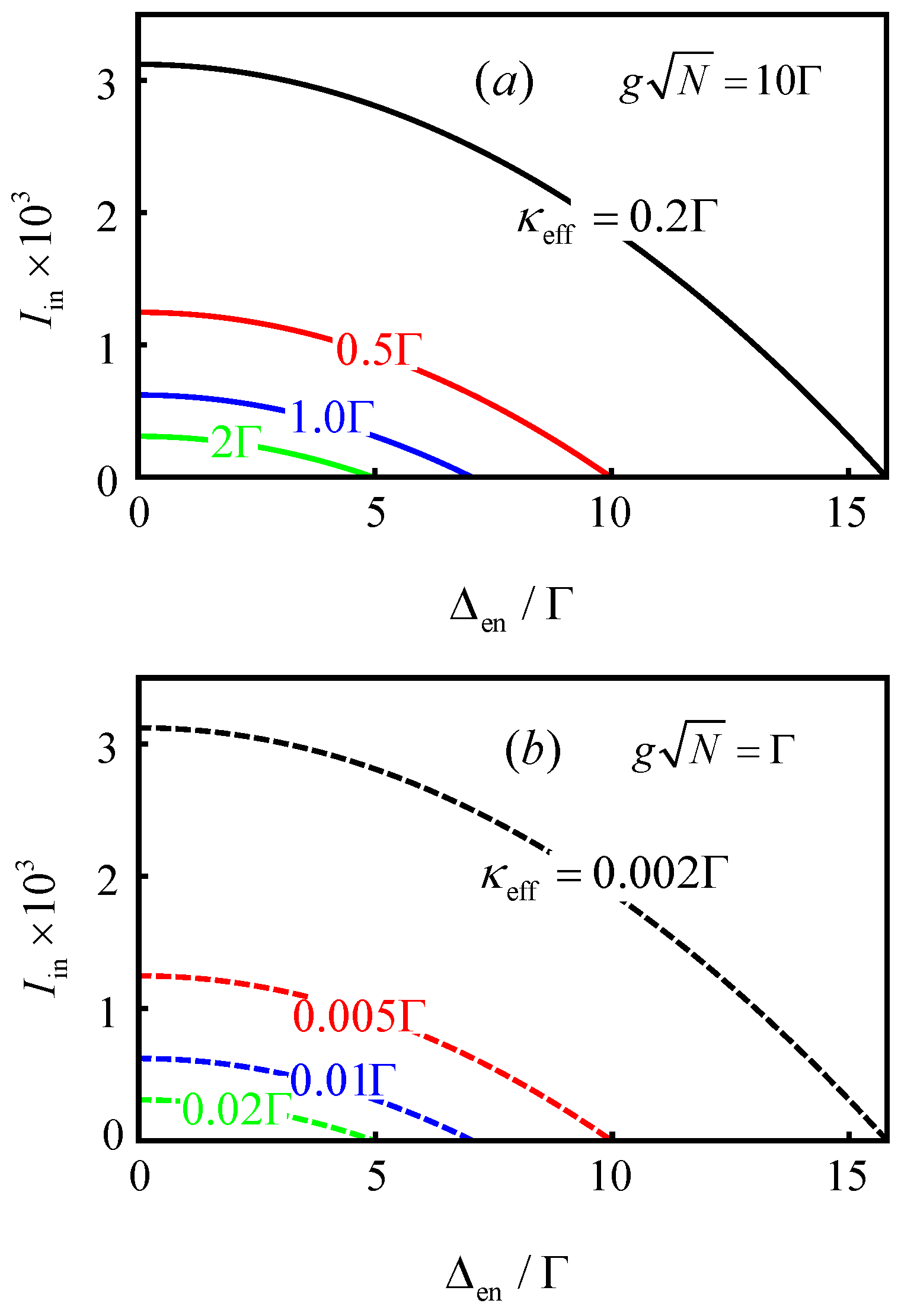
In Figure 2, we plot the input intensity I in as a function of the normalized detuning Δ en / Γ for two representative coupling strengths, g N = 10 Γ and g N = Γ , corresponding to the strong- and weak-coupling regimes, respectively (with κ = 3 Γ ). As seen in Figure 2a,b, CPA occurs within the same detuning range Δ en 2 < Δ T 2 for both regimes, provided that G and θ are tuned to adjust κ eff . Under the CPA condition, the input intensity can be expressed as I in = T n α , and the transition from the linear to the nonlinear regime occurs when I in T n s , where n s = Γ 2 / ( 4 g 2 ) denotes the intracavity saturation intensity in free space. By comparing Figure 2a,b, we conclude that the system can enter the nonlinear regime even under weak coupling by adopting a very small effective decay rate, e.g., κ eff = 0.02 Γ (green), 0.01 Γ (blue), 0.005 Γ (red), and 0.002 Γ (black). This result is consistent with the findings of Ref. [27] for the strong-coupling regime. Moreover, Figure 2a,b show that decreasing κ eff broadens the accessible ranges of both input intensity I in and frequency detuning Δ en for observing CPA.

4. CPA

To further investigate, we perform numerical simulations to verify the occurrence of CPA in both strong- and weak-coupling regimes. Additionally, we analyze the influence of the OPA on the output intensity, defined as I out = | a out | 2 . A vanishing output intensity ( I out = 0 ) indicates the realization of coherent perfect absorption.

4.1. Strong Coupling

As shown in Figure 2a [see the four curves], coherent perfect absorption (CPA) occurs only within the detuning range Δ en < Δ T in the strong-coupling regime. Without loss of generality, we focus on the green curve for detailed analysis. Accordingly, all parameters in this section are chosen to match those of the green curve in Figure 2a. To realize an effective decay rate κ eff = 2 Γ , the OPA parameters G and θ [ π / 2 , 3 π / 2 ] can be appropriately tuned within the reach of current experimental techniques. Specifically, the following parameter sets, { G , cos θ } = { 0.5 Γ , 1 } , { Γ , 0.5 } , { 2 Γ , 0.25 } , are employed to investigate CPA in the strong-coupling regime. Figure 3 presents the output intensity I out as a function of the input intensity I in for normalized frequency detunings Δ en / Γ = 4 , 3 , and 1. The red, blue, and green curves correspond to the parameter sets listed above, while the cavity detuning Δ c is determined from Equation (14).
As discussed in Ref. [27], when Δ en approaches the threshold Δ T , a CQED system without an OPA operates in the linear regime. For detunings Δ en < Δ T and input intensities I in > T n s , the system enters the nonlinear regime. Figure 3a–c show that the output intensity varies nonlinearly with the input intensity in the CQED system incorporating an OPA. Moreover, CPA ( I out = 0 ) occurs when the input intensity reaches a certain value under the chosen parameters. From Figure 3a–c, we see that different { G , θ } values can tune the output intensity but do not alter the occurrence of CPA. Specifically, increasing G suppresses the output intensity at high input intensities while enhancing it at low input intensities. Comparing Figure 3a–c, we observe that achieving CPA requires a stronger input intensity as Δ en decreases. Furthermore, as Δ en decreases, the output intensity gradually exhibits bistable behavior (Figure 3b,c), indicating that the system enters a highly nonlinear regime. In this bistable regime, more intricate bistable patterns emerge with increasing G for a fixed Δ en (Figure 3b,c). Notably, CPA occurs outside the bistable regime in Figure 3a, but within the bistable regime in Figure 3b,c as Δ en decreases.

4.2. Weak Coupling

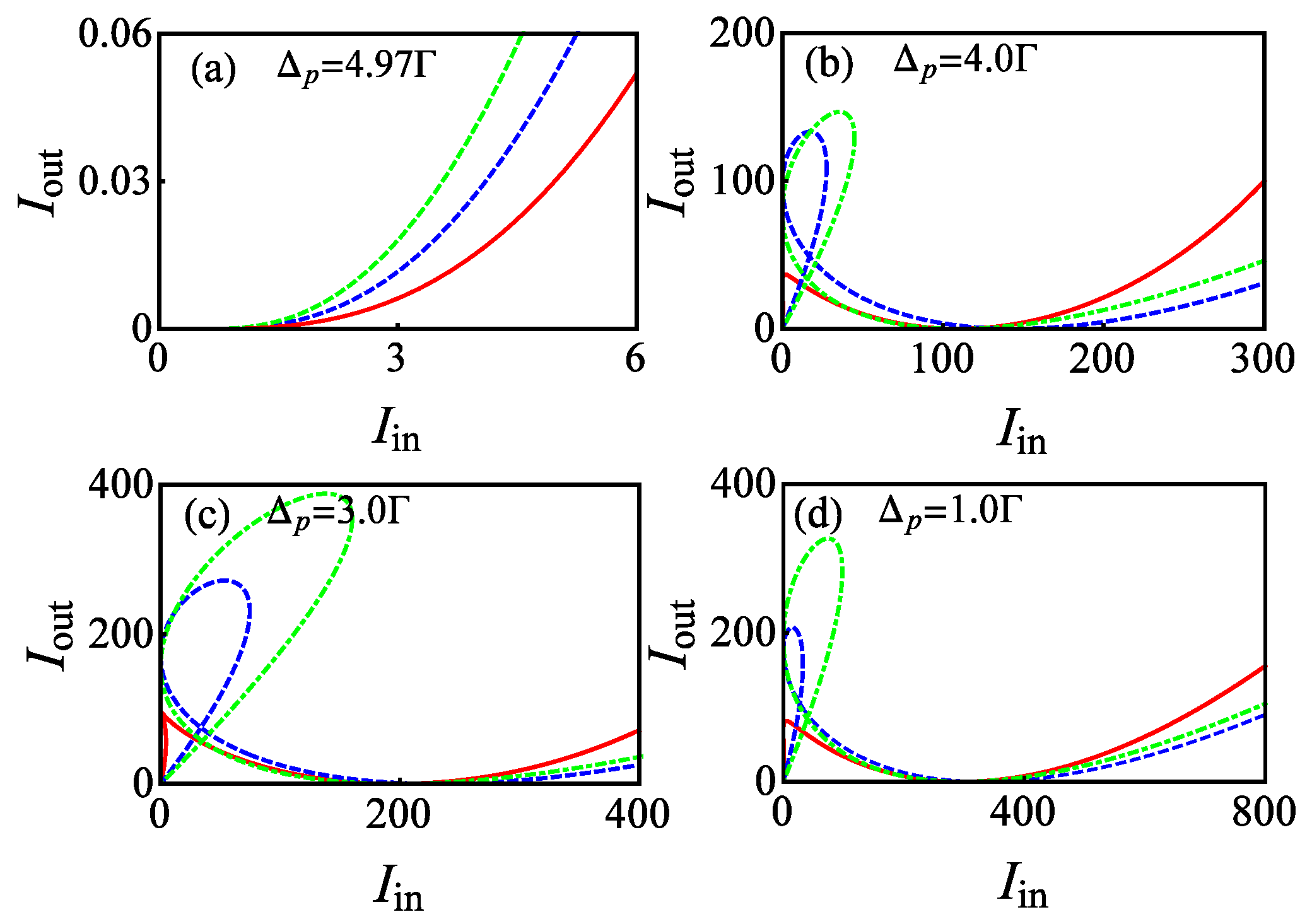
As shown in Figure 2b, CPA in the weak-coupling regime can be observed within the same detuning range as in the strong-coupling regime. Similar to the previous analysis for the strong-coupling case, we focus on the green curve in Figure 2b for a detailed study. To achieve an effective decay rate κ eff = 0.02 Γ , the following OPA parameter sets are chosen: { G , cos θ } = { 2 Γ , 0.745 } , { 3 Γ , 0.497 } , { 4 Γ , 0.3725 } , with θ [ π / 2 , 3 π / 2 ] . Figure 4 shows the output intensity I out as a function of the input intensity I in for normalized frequency detunings Δ en / Γ = 4.97 , 4 , 3 , and 1. The red, blue, and green curves correspond to the parameter sets listed above, which ensure that κ eff remains fixed at 0.02 Γ .
From Figure 4a, when Δ en is close to the threshold Δ T = 4.975 , e.g., Δ en = 4.97 Γ , the system approximately operates in the linear regime. In this case, CPA occurs only within a narrow range of input intensities, consistent with the strong-coupling results reported in Ref. [27]. Unlike Ref. [27], however, the output intensity in this linear regime can be tuned by adjusting G and θ , with higher G values enhancing the output intensity.
When the detuning is further reduced to Δ en = 4.0 Γ , 3.0 Γ , and 1.0 Γ (Figure 4b–d), the system enters the nonlinear regime. In this regime, the output intensity exhibits bistability, with more intricate bistable patterns appearing in the weak-input-intensity region, i.e., for I in below the value corresponding to I out = 0 . In contrast to the strong-coupling case, the output intensity in the strong-input-intensity region (where I in exceeds the CPA point) is initially suppressed and subsequently enhanced as G increases. Notably, in the weak-coupling regime, CPA does not occur within the bistable region.

5. Conclusions

In summary, we have investigated coherent perfect absorption (CPA) in a system comprising an ensemble coupled to a cavity containing an optical parametric amplifier (OPA). Our analysis shows that CPA can be realized in both strong- and weak-coupling regimes. Specifically, when the OPA introduces an effective loss, CPA occurs only in the strong-coupling regime. In contrast, when the OPA induces a gain effect, CPA can be achieved in both the strong- and weak-coupling regimes. Furthermore, in the strong-coupling regime, CPA can occur within the bistable region of the output intensity, whereas in the weak-coupling regime, CPA is observed only outside the bistable region. We also demonstrate that the output intensity can be actively tuned via the OPA parameters. These findings provide a promising route for exploring other quantum phenomena in systems where achieving strong coupling remains experimentally challenging.

Author Contributions

Conceptualization, J.C. and W.X.; Formal analysis, Y.-X.C. and Y.-X.W.; Writing—original draft, Z.-W.L., J.C. and W.X.; Writing—review & editing, J.C. and W.X.; Supervision, J.C. and W.X. All authors have read and agreed to the published version of the manuscript.

Funding

This work was supported by the Natural Science Foundation of Zhejiang Province (Grant No. LY24A040004).

Data Availability Statement

The original contributions presented in this study are included in the article. Further inquiries can be directed to the corresponding authors.

Conflicts of Interest

The authors declare no conflicts of interest.

References

  1. Julsgaard, B.; Sherson, J.; Cirac, J.; Fiurášek, J.; Polzik, E.S. Experimental demonstration of quantum memory for light. Nature 2004, 432, 482. [Google Scholar] [CrossRef]
  2. Reithmaier, J.P.; Sęk, G.; Löffler, A.; Hofmann, C.; Kuhn, S.; Reitzenstein, S.; Keldysh, L.V.; Kulakovskii, V.D.; Reinecke, T.L.; Forchel, A. Strong coupling in a single quantum dot–semiconductor microcavity system. Nature 2004, 432, 197. [Google Scholar] [CrossRef] [PubMed]
  3. Yoshie, T.; Scherer, A.; Hendrickson, J.; Khitrova, G.; Gibbs, H.M.; Rupper, G.; Ell, C.; Shchekin, O.B.; Deppe, D.G. Vacuum Rabi splitting with a single quantum dot in a photonic crystal nanocavity. Nature 2004, 432, 200. [Google Scholar] [CrossRef] [PubMed]
  4. Almeida, V.R.; Barrios, C.A.; Panepucci, R.R.; Lipson, M. All-optical control of light on a silicon chip. Nature 2004, 431, 1081. [Google Scholar] [CrossRef] [PubMed]
  5. Tanabe, T.; Notomi, M.; Mitsugi, S.; Shinya, A.; Kuramochi, E. Fast all-optical switching using ion-implanted silicon photonic crystal nanocavities. Appl. Phys. Lett. 2005, 87, 151112. [Google Scholar] [CrossRef]
  6. Birnbaum, K.M.; Boca, A.; Miller, R.; Boozer, A.D.; Northup, T.E.; Kimble, H.J. Photon blockade in an optical cavity with one trapped atom. Nature 2005, 436, 87. [Google Scholar] [CrossRef]
  7. Zhang, G.Q.; Wang, Y.; Xiong, W. Detection sensitivity enhancement of magnon Kerr nonlinearity in cavity magnonics induced by coherent perfect absorption. Phys. Rev. B 2023, 107, 064417. [Google Scholar] [CrossRef]
  8. Shen, R.C.; Li, J.; Sun, Y.M.; Wu, W.J.; Zuo, X.; Wang, Y.P.; Zhu, S.Y.; You, J.Q. Cavity-magnon polaritons strongly coupled to phonons. Nat. Commun. 2025, 16, 5652. [Google Scholar] [CrossRef]
  9. Zhang, D.; Luo, X.Q.; Wang, Y.P.; Li, T.F.; You, J.Q. Observation of the exceptional point in cavity magnon–polaritons. Nat. Commun. 2017, 8, 1368. [Google Scholar] [CrossRef]
  10. Xiong, W.; Chen, J.; Fang, B.; Lam, C.H.; You, J.Q. Coherent perfect absorption in a weakly coupled atom-cavity system. Phys. Rev. A 2020, 101, 063822. [Google Scholar] [CrossRef]
  11. Wiersma, D.S.; Bartolini, P.; Lagendijk, A.; Righini, R. Localization of light in a disordered medium. Nature 1997, 390, 671. [Google Scholar] [CrossRef]
  12. Störzer, M.; Gross, P.; Aegerter, C.M.; Maret, G. Observation of the critical regime near Anderson localization of light. Phys. Rev. Lett. 2006, 96, 063904. [Google Scholar] [CrossRef]
  13. Jović, D.M.; Denz, C.; Belić, M.R. Anderson localization of light in PT-symmetric optical lattices. Opt. Lett. 2012, 37, 4455. [Google Scholar] [CrossRef]
  14. Hau, L.V.; Harris, S.E.; Dutton, Z.; Behroozi, C.H. Light speed reduction to 17 metres per second in an ultracold atomic gas. Nature 1999, 397, 594. [Google Scholar] [CrossRef]
  15. Melentiev, P.N.; Afanasiev, A.E.; Kuzin, A.A.; Baturin, A.S.; Balykin, V.I. Subwavelength light localization based on optical nonlinearity and light polarization. Opt. Lett. 2013, 38, 2274. [Google Scholar] [CrossRef]
  16. Fleischhauer, M.; Lukin, M.D. Dark-state polaritons in electromagnetically induced transparency. Phys. Rev. Lett. 2000, 84, 5094. [Google Scholar] [CrossRef]
  17. Zanotto, S.; Mezzapesa, F.P.; Bianco, F.; Biasiol, G.; Baldacci, L.; Vitiello, M.S.; Sorba, L.; Colombelli, R.; Tredicucci, A. Perfect energy-feeding into strongly coupled systems and interferometric control of polariton absorption. Nat. Phys. 2014, 10, 830. [Google Scholar] [CrossRef]
  18. Chong, Y.D.; Ge, L.; Cao, H.; Stone, A.D. Coherent perfect absorbers: Time-reversed lasers. Phys. Rev. Lett. 2010, 105, 053901. [Google Scholar] [CrossRef] [PubMed]
  19. Wan, W.; Chong, Y.; Ge, L.; Noh, H.; Stone, A.D.; Cao, H. Time-reversed lasing and interferometric control of absorption. Science 2011, 331, 889. [Google Scholar] [CrossRef] [PubMed]
  20. Dutta, G.S. Strong-interaction-mediated critical coupling at two distinct frequencies. Opt. Lett. 2007, 32, 1483. [Google Scholar] [CrossRef]
  21. Gmachl, C.F. Suckers for light. Nature 2010, 467, 37. [Google Scholar] [CrossRef] [PubMed]
  22. Dutta-Gupta, S.; Deshmukh, R.; Gopal, A.V.; Martin, O.J.F.; Gupta, S.D. Coherent perfect absorption mediated anomalous reflection and refraction. Opt. Lett. 2012, 37, 4452. [Google Scholar] [CrossRef] [PubMed]
  23. Yoon, J.W.; Koh, G.M.; Song, S.H.; Magnusson, R. Measurement and modeling of a complete optical absorption and scattering by coherent surface plasmon-polariton excitation using a silver thin-film grating. Phys. Rev. Lett. 2012, 109, 257402. [Google Scholar] [CrossRef] [PubMed]
  24. Huang, S.; Agarwal, G.S. Coherent perfect absorption of path entangled single photons. Opt. Express 2014, 22, 20936. [Google Scholar] [CrossRef]
  25. Roger, T.; Vezzoli, S.; Bolduc, E.; Valente, J.; Heitz, J.J.F.; Jeffers, J.; Soci, C.; Leach, J.; Couteau, C.; Zheludev, N.I.; et al. Coherent perfect absorption in deeply subwavelength films in the single-photon regime. Nat. Commun. 2015, 6, 7031. [Google Scholar] [CrossRef]
  26. Agarwal, G.S.; Zhu, Y. Photon trapping in cavity quantum electrodynamics. Phys. Rev. A 2015, 92, 023824. [Google Scholar] [CrossRef]
  27. Agarwal, G.S.; Di, K.; Wang, L.; Zhu, Y. Perfect photon absorption in the nonlinear regime of cavity quantum electrodynamics. Phys. Rev. A 2016, 93, 063805. [Google Scholar] [CrossRef]
  28. Wang, L.; Di, K.; Zhu, Y.; Agarwal, G.S. Interference control of perfect photon absorption in cavity quantum electrodynamics. Phys. Rev. A 2017, 95, 013841. [Google Scholar] [CrossRef]
  29. Agarwal, G.S. Vacuum-field Rabi splittings in microwave absorption by Rydberg atoms in a cavity. Phys. Rev. Lett. 1984, 53, 1732. [Google Scholar] [CrossRef]
  30. Raizen, M.G.; Thompson, R.J.; Brecha, R.J.; Kimble, H.J.; Carmichael, H.J. Normal-mode splitting and linewidth averaging for two-state atoms in an optical cavity. Phys. Rev. Lett. 1989, 63, 240. [Google Scholar] [CrossRef]
  31. Zhu, Y.; Gauthier, D.J.; Morin, S.E.; Wu, Q.; Carmichael, H.J.; Mossberg, T.W. Vacuum Rabi splitting as a feature of linear-dispersion theory: Analysis and experimental observations. Phys. Rev. Lett. 1990, 64, 2499. [Google Scholar] [CrossRef] [PubMed]
  32. Law, C.K. Vacuum Rabi oscillation induced by virtual photons in the ultrastrong-coupling regime. Phys. Rev. A 2013, 87, 045804. [Google Scholar] [CrossRef]
  33. Tabuchi, Y.; Ishino, S.; Ishikawa, T.; Yamazaki, R.; Usami, K.; Nakamura, Y. Hybridizing ferromagnetic magnons and microwave photons in the quantum limit. Phys. Rev. Lett. 2014, 113, 083603. [Google Scholar] [CrossRef] [PubMed]
  34. Abdurakhimov, L.V.; Bunkov, Y.M.; Konstantinov, D. Normal-mode splitting in the coupled system of hybridized nuclear magnons and microwave photons. Phys. Rev. Lett. 2015, 114, 226402. [Google Scholar] [CrossRef]
  35. Yang, G.; Gu, W.J.; Li, G.; Zou, B.; Zhu, Y. Quantum nonlinear cavity quantum electrodynamics with coherently prepared atoms. Phys. Rev. A 2015, 92, 033822. [Google Scholar] [CrossRef]
  36. Zhang, Y.; Sohail, A.; Yu, C. Perfect photon absorption in hybrid atom-optomechanical system. Europhys. Lett. 2016, 115, 64002. [Google Scholar] [CrossRef]
  37. Agarwal, G.S.; Huang, S. Nanomechanical inverse electromagnetically induced transparency and confinement of light in normal modes. New J. Phys. 2014, 16, 033023. [Google Scholar] [CrossRef]
  38. Colombe, Y.; Steinmetz, T.; Dubois, G.; Linke, F.; Hunger, D.; Reichel, J. Strong atom–field coupling for Bose–Einstein condensates in an optical cavity on a chip. Nature 2007, 450, 272. [Google Scholar] [CrossRef]
  39. Kubo, Y.; Ong, F.R.; Bertet, P.; Vion, D.; Jacques, V.; Zheng, D.; Dréau, A.; Roch, J.-F.; Auffeves, A.; Jelezko, F.; et al. Strong coupling of a spin ensemble to a superconducting resonator. Phys. Rev. Lett. 2010, 105, 140502. [Google Scholar] [CrossRef]
  40. Aharonovich, I.; Greentree, A.D.; Prawer, S. Diamond photonics. Nat. Photonics 2011, 5, 397. [Google Scholar] [CrossRef]
  41. Hu, X.; Liu, Y.; Nori, F. Strong coupling of a spin qubit to a superconducting stripline cavity. Phys. Rev. B 2012, 86, 035314. [Google Scholar] [CrossRef]
  42. Mercurio, A.; Abo, S.; Mauceri, F.; Russo, E.; Macrì, V.; Miranowicz, A.; Savasta, S.; Stefano, O.D. Pure dephasing of light-matter systems in the ultrastrong and deep-strong coupling regimes. Phys. Rev. Lett. 2023, 130, 123601. [Google Scholar] [CrossRef] [PubMed]
  43. Macrì, V.; Mercurio, A.; Nori, F.; Savasta, S.; Sánchez, C. Spontaneous scattering of Raman photons from cavity-QED systems in the ultrastrong coupling regime. Phys. Rev. Lett. 2022, 129, 273602. [Google Scholar] [CrossRef] [PubMed]
  44. Macrì, V.; Minganti, F.; Kockum, A.F.; Ridolfo, A.; Savasta, S.; Nori, F. Revealing higher-order light and matter energy exchanges using quantum trajectories in ultrastrong coupling. Phys. Rev. A 2022, 105, 023720. [Google Scholar] [CrossRef]
  45. Minganti, F.; Macrì, V.; Settineri, A.; Savasta, S.; Nori, F. Dissipative state transfer and Maxwell’s demon in single quantum trajectories: Excitation transfer between two noninteracting qubits via unbalanced dissipation rates. Phys. Rev. A 2021, 103, 052201. [Google Scholar] [CrossRef]
  46. Mollow, B.R.; Glauber, R.J. Quantum theory of parametric amplification. I. Phys. Rev. 1967, 160, 1076. [Google Scholar] [CrossRef]
  47. Walls, D.F.; Milburn, G.J. Quantum Optics; Springer: Berlin/Heidelberg, Germany, 1994. [Google Scholar]
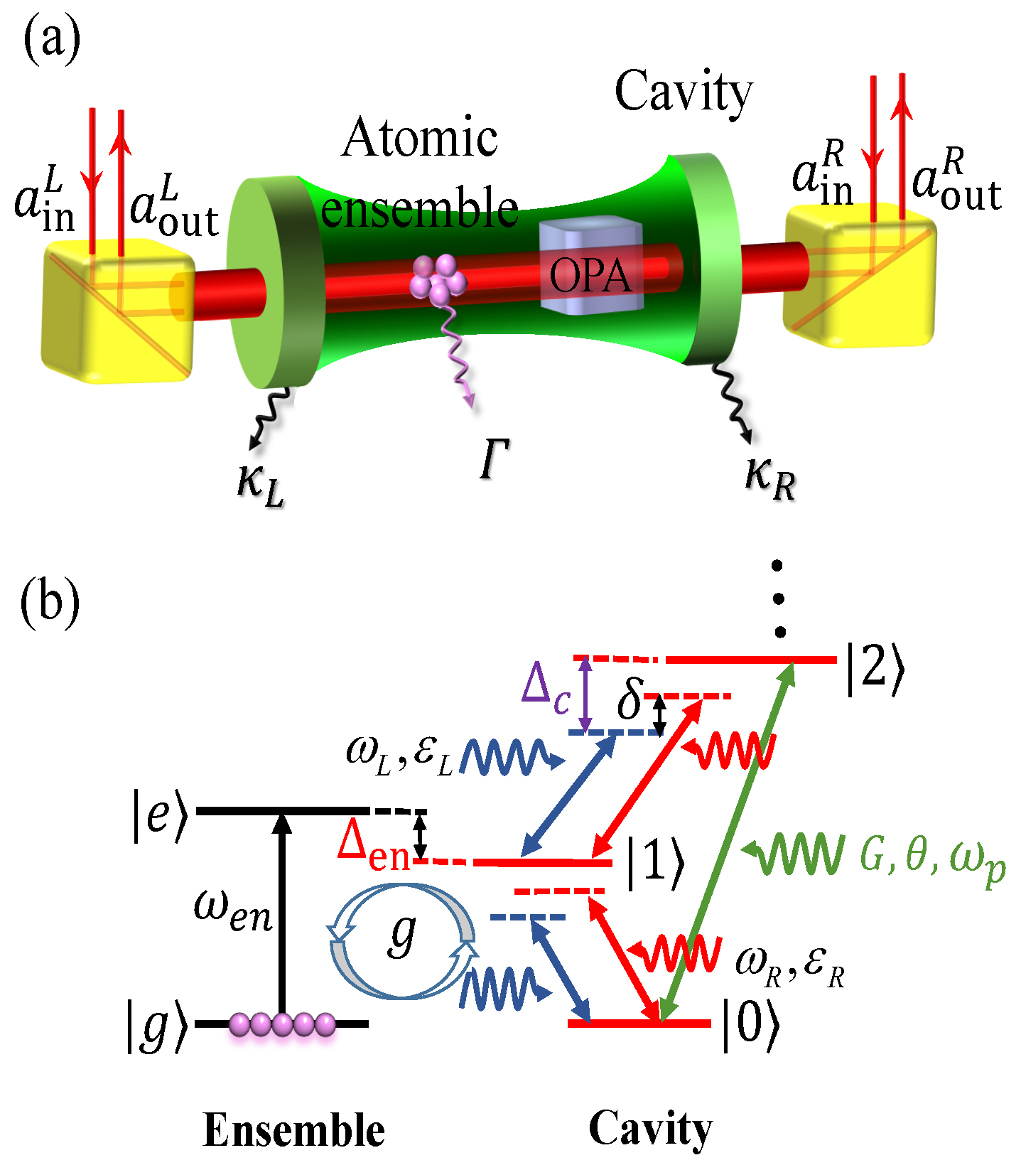
Figure 1. (Color online) (a) Schematic diagram of the system consisting of a two-level atomic ensemble coupled to an optical cavity that contains an OPA. The cavity is driven by two coherent input fields. (b) Energy-level structure of the atomic ensemble. The red arrow indicates the coupling between the ensemble and the cavity mode with frequency ω c , while the green arrow represents the interaction between the ensemble and the input fields with frequency ω p . The frequency detunings of the input fields from the cavity and ensemble are denoted by Δ c and Δ en , respectively.
Photonics 12 01135 g001
Figure 2. (Color online) Input intensity I in versus the normalized parameter Δ en / Γ under CPA conditions. (a) Strong coupling regime with g N = 10 Γ and κ eff = 0.2 Γ (black), 0.5 Γ (red), 1 Γ (blue), and 2 Γ (green). (b) Weak coupling regime with g N = Γ and κ eff = 0.002 Γ (black), 0.005 Γ (red), 0.01 Γ (blue), and 0.02 Γ (green). Here g = 0.02 Γ and T = 0.01 .
Photonics 12 01135 g002
Figure 3. (Color online) The output intensity I out as a function of the input intensity I in under CPA condition for different frequency detunings of the ensemble from the left input field: (a) Δ p = 4.0 Γ , (b) Δ p = 3.0 Γ and (c) Δ p = 1.0 Γ . Three chromatic curves in red, blue and green respectively correspond to { G , cos θ } = { 0.5 Γ , 1 } , { Γ , 0.5 } , { 2 Γ , 0.25 } . Other parameters are the same as in Figure 2 and κ = 3 Γ is assumed. These parameters lead to the effective decay rate κ eff = 2 Γ .
Photonics 12 01135 g003
Figure 4. (Color online) The output intensity I out as a function of the input intensity I in under CPA condition for different frequency detunings of the ensemble from the left input field: (a) Δ p = 4.97 Γ , (b) Δ p = 4.0 Γ , (c) Δ p = 3.0 Γ , (d) Δ p = 1.0 Γ . Three chromatic curves in red, blue and green respectively correspond to { G , cos θ } = { 2 Γ , 0.745 } , { 3 Γ , 0.497 } , { 4 Γ , 0.3725 } . Other parameters are the same as in Figure 2 and κ = 3 Γ is assumed. These parameters lead to the effective decay rate κ eff = 0.02 Γ .
Photonics 12 01135 g004
Disclaimer/Publisher’s Note: The statements, opinions and data contained in all publications are solely those of the individual author(s) and contributor(s) and not of MDPI and/or the editor(s). MDPI and/or the editor(s) disclaim responsibility for any injury to people or property resulting from any ideas, methods, instructions or products referred to in the content.