Communication

Laser Radar System Based on Lightweight Diffractive Lens Receiver System

National Key Laboratory of Light Field Control Science and Technology, Institute of Optics and Electronics, Chinese Academy of Sciences, Chengdu 610209, China
*
Author to whom correspondence should be addressed.
Photonics 2025, 12(1), 86; https://doi.org/10.3390/photonics12010086
Submission received: 16 November 2024 / Revised: 15 January 2025 / Accepted: 16 January 2025 / Published: 17 January 2025
(This article belongs to the Special Issue Diffractive Optics and Its Emerging Applications)

Abstract

:
Diffractive lens has advantages over traditional reflective lens, such as light weight, high folding compression ratio, high tolerance for surface figure error and low manufacturing costs. It provides a new technical approach for a lightweight LiDAR ranging system. In this work, a laser radar system based on a diffractive lens receiver system has been designed. The receiver system is a hybrid structure consisting of an eight-level diffractive lens, a collimation set and a convergence set. Combined with the single photodetector, the designed laser radar system can simultaneously achieve measurements at near-field distances of 6.0 m, 9.9 m, and 16.1 m and far-field distances of 851.2 m.

1. Introduction

A laser radar, commonly known as LIDAR (Light Detection and Ranging), is a remote sensing technology that uses laser light to measure distances to objects [1,2,3,4]. As demand increases for high-resolution, integrated, and lightweight solutions in laser radar, particularly for large-aperture applications, research on laser radar systems is steadily expanding. A laser radar system based on a diffractive lens uses diffractive lens as part of the receiving optical system to focus and collect reflected laser signals from targets [5,6]. In such a system, the use of diffractive lens offers unique advantages in terms of lightweight design, high efficiency, customization, reduced aberrations, and cost-effectiveness. Moreover, by leveraging the characteristic of energy concentration at the focal point for the designed wavelength, diffractive lens-based optical receiving systems are highly valuable in applications where monochromatic light is used for detection.
In 1972, the US Atmospheric Research Center developed an airborne laser radar system using a dye laser as the pulse light source and using a Fresnel lens as the light signal receiving part. This system, with a diameter of 38 cm and weighing 60 kg, was aimed at providing spatial distribution data of aerosols in the stratosphere [7]. In 2014, NASA developed a differential absorption LIDAR system with a diameter of 30.5 cm, designed for detecting ozone distribution at heights ranging from 100 to 500 m. The receiver of this system consisted of a Fresnel lens and a polycarbonate cone bonded together, with a mass of 0.91 kg [8].
Research on laser radar receiving systems based on diffractive lenses began relatively late in China. The Xi’an Institute of Optics and Precision Mechanics of the Chinese Academy of Sciences completed the design of a diffractive laser radar receiving system with a diameter of 1 m based on the Schupmann achromatic model [9]. In 2022, the Aerospace Information Research Institute of the Chinese Academy of Sciences introduced a solution for a dual-wavelength laser radar system with a 2 m aperture. This system was developed in response to the demand for three-dimensional imaging of the Earth and ocean depth measurement, utilizing harmonic diffractive technology and coherent detection techniques. However, there has been limited public reporting on the specific design methods and performance verification results of the diffractive receiving system [10,11].
The creation of diffractive optical elements is a sophisticated field that has seen significant advancements in recent years, with various techniques available for their production. These techniques are crucial for applications such as beam shaping, optical data storage, and laser systems. The main methods for producing DOEs include photolithography, Electron-beam Lithography (EBL), grayscale lithography (GSL), direct laser writing (DLW), Nanoimprint Lithography (NIL), 3D Printing and Holographic Lithography. The ongoing development in this field is driven by the demand for more efficient, higher performing, and cost-effective optical components [12,13,14,15,16,17,18]. Two prominent techniques for producing DOEs are photolithography and grayscale lithography, because they can both offer high contrast, which is crucial for precise pattern transfer [14,19]. But photolithography requires less complex equipment and is generally more cost-effective.
In this research, a laser radar system based on a lightweight diffractive lens receiver was designed. The receiver system features a hybrid structure consisting of a diffractive lens, a collimation set, and a convergence set. The diffractive lens used in the receiver system has eight levels, an F-number of 1.78, and a diffraction efficiency of 78.2%. Combined with a single photodetector, the designed laser radar system can achieve measurements at near-field distances of 6.0 m, 9.9 m, and 16.1 m and far-field distances of 851.2 m.

2. Materials and Methods

2.1. Diffractive Lens

Compared with the traditional Fresnel lens, staircase diffractive surfaces lenses can achieve a reduction in light loss without increasing surface roughness, enabling the realization of optical designs that approach the scalar diffraction limit. Other than that, staircase diffractive surfaces lenses can increase the light flux efficiency of optical heads, which is particularly useful in applications requiring high light efficiency. So they can perform better in chromatic aberration control compared to Fresnel lenses, which is crucial for achieving chromatic correction and improving image quality. These advantages make staircase diffractive lenses promising for high-precision optical systems and imaging technologies [20,21,22]. The photolithography of the eight-level lightweight diffractive lens (as shown in Figure 1) is carried out using an LDW system (DWL66+, Heidelberg, Germany) with a positioning error of 100 nm (3σ). The pattern transfer process is performed using a Reactive Ion Etching machine (RIE600, developed by the Institute of Optics and Electronics, Chengdu, China). A schematic diagram of the diffractive pattern fabrication process is shown in Figure 2. The lightweight diffractive lens is made by designed optical level polyimide film (the thickness of the film is 25 µm) with high dimensional stability, high mechanical strength and high optical homogeneity [23,24]. The photolithography of the flexible polyimide membrane is conducted by a vacuum-assisted self-contact method [25].

2.2. Receiver System

The receiver system is a hybrid structure consisting of an eight-level lightweight diffractive lens, a collimation set and a refocus set. The schematic is shown in Figure 3. The reflected signal from the target passes through the diffractive lens and reaches the variable pinhole, which acts as a field diaphragm to suppress background light from reaching the detector. The collimation set (#64-765, Edmund, Barrington, NJ, USA) and the spike filter are both used to filter out wavelengths other than the designed wavelength. Finally, the light is focused on the detector by the refocusing system to enable the collection and detection of the return signal.

2.3. Laser Radar Distance Test System

The light path in the laser radar system based on a diffractive lens is illustrated in Figure 4. First, a laser pulse (1064 nm) is emitted by the laser, and the energy of this pulse is split into two parts after passing through the beam splitter (1:99). One part of the laser energy (1%) is directed onto the target surface of the photodiode (PIN, DET100A2, Thorlabs, Newton, NJ, USA), generating an electrical pulse signal. The arrival time of this pulse signal is recorded as the start time, t1. The other part of the laser energy (99%) is directed toward the target, and the energy of the echo after diffuse reflection from the target is collected by the receiving system and focused on the target surface of the single-photon detector (GM-APD, CD3565H SPAD, Excelitas, Pittsburgh, PA, USA). The arrival time of the electrical pulse signal generated at this point is recorded as the end time, t2. By measuring the round-trip time interval of the light pulse, Δt (Δt = t2 − t1), the distance between the LIDAR and the target object can be calculated using the formula L = c⋅Δt/2, where c is the speed of light. In the system, time-correlated single-photon counting (TCSPC) is used to achieve effective detection of target distance [26].

3. Results and Discussion

3.1. The Design of the Lightweight Diffractive Lens

The diffraction efficiency of the primary lens is a key factor in determining the system’s throughput, which directly affects the detection accuracy of optical receiving systems in laser radar applications. When incident light passes through the surface microstructure, it is diffracted into the desired working order, achieving the goal of converging the beam through the diffractive lens. We designed and analyzed parameters for diffractive lenses with 2, 4, and 8 steps separately, based on the aforementioned laser radar system, operating in the 1064 nm wavelength band. The theoretical diffraction efficiency for each lens configuration was then assessed, as shown in Table 1. According to the Huygens–Fresnel integral method, simulations were conducted using Zemax software (2014) to obtain the point spread function (PSF) results for diffractive receiving objectives with two, four, and eight steps [27,28]. Figure 5b,d,f illustrates the point spread functions (PSFs) for diffractive lenses with two, four, and eight steps. These data aim to describe the optical system’s response to a point light source. Primarily, it refers to the distribution of light intensity formed on the image plane after a point source passes through the diffractive lenses with two, four, and eight steps. The PSF data can be directly correlated to the system’s resolution and image quality. The PSF results (Figure 5a,c,e), where the black curves represent continuous surface simulations and the red curves represent simulations for two, four, and eight-step structures), indicate that for on-axis object points at infinity, the image quality of eight-level diffractive receiving objective is the best, with a more concentrated intensity distribution on the focal plane. Additionally, as shown in Figure 5b,d,f, the theoretical diffraction efficiency of the eight-step diffractive lens is approximately 94.78%, significantly higher than the efficiency of 80.96% for the four-step lens and 40.53% for the two-step lens, as summarized in Table 1. Based on these findings, an eight-step diffractive lens is proposed for the laser radar system to achieve higher measurement accuracy.

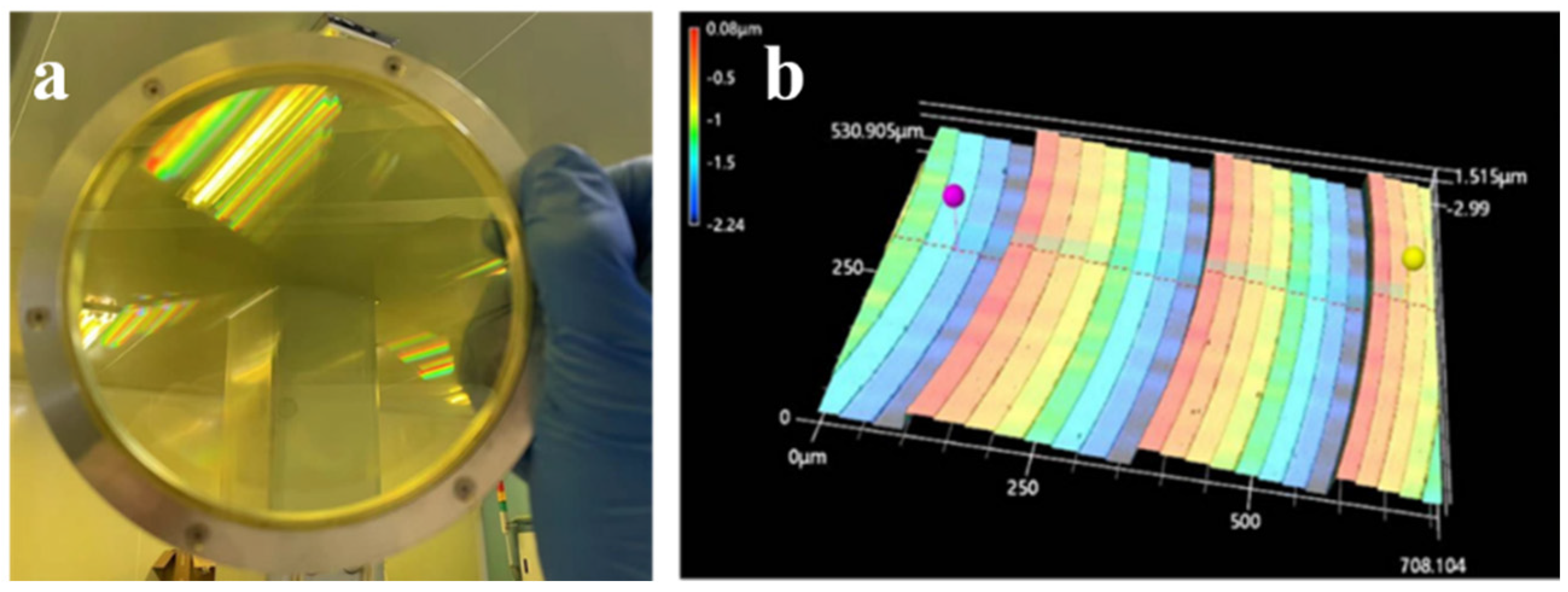
3.2. The Fabrication and Performance of Eight-Level Diffractive Lens

The eight-level diffractive lens was fabricated by photolithography and was made in optical-quality lightweight polyimide substrate with Φ50 mm diffractive pattern (Figure 6a). The etching depth and linewidth of each level were measured by confocal microscopy. The partial structure profilometer test results are shown in Figure 6b. The depth of each level is uniform (268 nm) across the whole diffractive pattern. The linewidth increases from the outer edge to inner edge. The smallest linewidth is 1.5 µm. The diffraction efficiency of the fabricated diffractive receiving objective was tested, and a diffraction efficiency testing setup was constructed. The measured average diffraction efficiency result was 78.2%. The reason for the lower diffraction efficiency compared to the theoretical values is mainly due to alignment errors and overlay errors during the fabrication process.

3.3. Distance Test

To validate the feasibility of applying a diffractive lens-based receiving optical system in a laser radar system, short- and long-distance ranging experiments were conducted. The constructed photon-counting LiDAR ranging device is shown in Figure 7. The laser with a central wavelength of 1064 nm has a repetition frequency of 5 kHz, a pulse width of 10 ns, and a laser divergence angle of 1 mrad. The beam splitter has a splitting ratio of 1:99. The photosensitive surface diameter of the photodiode (PIN) is 9.8 mm. The single-photon detector (SPAD) used is the CD3565H SPAD produced by Excelitas, with a dead time of 41.3 ns and a photon detection efficiency of 2.8%. The time resolution of the TCSPC module is 512 ps. The designed eight-level diffractive lens was used in the system as part of the receiving system. The aperture of the diffractive lens is 50 mm, with a field of view of 0.9 mrad and an average diffraction efficiency of 78.2%.
The experiments were conducted at night under good weather conditions. In the short-distance ranging experiments, a white paper (210 mm × 297 mm) was used as a target. The obtained photon-counting histograms for the echo of the A4 paper target are shown in Figure 8a–c. In the figures, the horizontal axis represents the measured distance, and the vertical axis represents the number of echo photons counted. From the short-range test results, it can be observed that the distances between the A4 white paper and the experimental setup are 6.0 m, 9.9 m, and 16.1 m, which are consistent with the actual distances of 6.0 m, 10.0 m, and 16.0 m, respectively. This demonstrates that the designed diffractive optical system applied to the LiDAR receiving end is effective and capable of successfully performing short-range measurements.
In the long-distance ranging experiments, a tall building was selected as the target and its distance was measured. The obtained photon-counting histogram for the echo of the building is shown in Figure 8d. In the figure, the horizontal axis represents the measured distance, and the vertical axis represents the number of echo photons counted. From the long-range test results, it can be seen that the measured distance between the building and the experimental setup is 851.2 m, which is consistent with the actual distance (853 m). This effectively demonstrates that the designed diffractive optical system applied to the LiDAR receiving end is effective and capable of successfully performing long-range measurements.

4. Conclusions

A set of laser radar optical receiving systems was designed and fabricated. In the system, the primary mirror is an eight-step lightweight diffractive lens. It was fabricated in accordance with current diffractive lens manufacturing capabilities. Testing and analysis indicate that the laser radar system based on this diffractive lens can measure near and far targets at distances of approximately 6.0 m, 9.9 m, and 16.1 m and 851.2 m, respectively. Compared with the traditional laser radar system, the diffractive lens offers advantages such as high design flexibility, lightweight construction, and looser surface tolerances. Conducting research on laser radar optical systems based on diffractive lens is of significant importance for advancing the development of lightweight laser radar optical systems for spaceborne, airborne, and shipborne applications.

Author Contributions

Writing—Original Draft Preparation, J.Y.; Writing—Review and Editing, J.Y.; Methodology, M.H.; Supervision, J.D.; Project Administration, B.F.; Funding Acquisition, J.B. All authors have read and agreed to the published version of the manuscript.

Funding

This work was supported by the Youth Innovation Promotion Association, Chinese Academy of Science (2023395), and the Key Program of Chinese Academy of Sciences (No. YA16K010).

Institutional Review Board Statement

Not applicable.

Informed Consent Statement

Informed consent was obtained from all subjects involved in the study.

Data Availability Statement

The data presented in this study are available on request from the corresponding author.

Conflicts of Interest

The authors declare no conflicts of interest.

References

  1. Yu, A.W.; Krainak, M.; Harding, D.J.; Abshire, J.B.; Sun, X.; Cavanaugh, J.F.; Valett, S.R.; Ramos-Izquierdo, L. Multi-beam laser altimeter system simulator for the LIDAR surface topography (LIST) mission. Laser Electro-Opt. 2012, 1509, 1–3. [Google Scholar]
  2. Gargoum, S.; El-Basyouny, K. Automated extraction of road features using LiDAR data: A review of LiDAR applications in transportation. In Proceedings of the 2017 4th International Conference on Transportation Information and Safety (ICTIS), Banff, AB, Canada, 8–10 August 2017; pp. 563–574. [Google Scholar]
  3. Winker, D.M.; Couch, R.H.; McCormick, M.P. An overview of LITE: NASA’s LIDAR in-space technology experiment. Proc. IEEE 1996, 84, 1835. [Google Scholar] [CrossRef]
  4. Brenner, A.C.; DiMarzio, J.P.; Zwally, H.J. Precision and accuracy of satellite radar and laser altimeter data over the continental ice sheet. Geosci. Remote Sens. 2007, 45, 321–331. [Google Scholar] [CrossRef]
  5. Serre, D.; Deba, P.; Koechlin, L. Fresnel interferometric imager: Ground-based prototype. Appl. Opt. 2009, 48, 2811–2820. [Google Scholar] [CrossRef]
  6. Raksasataya, T.; Deba, P.; Rivet, J.P.; Gili, R.; Serre, D.; Koechlin, L. Fresnel diffractive imager: Instrument for space mission in the visible and UV. Proc. SPIE 2010, 7732, 10. [Google Scholar]
  7. Grams, G.W.; Wyman, C.M. Measurements of stratospheric aerosols by airborne laser radar. J. Appl. Meteorol. Climatol. 1972, 11, 1108–1113. [Google Scholar] [CrossRef]
  8. De young, R.J.; Anthony, N.; Carrion, W.; Pliutau, D. Lightweight Inexpensive Ozone LIDAR Telescope Using a Plastic Fresnel Lens; NASA/TM-2014-218534; National Aeronautics & Space Administration: Washington, DC, USA, 2014.
  9. Zhu, J.; Xie, Y. Large aperture diffractive telescope design for space-based LIDAR receivers. Proc. SPIE 2015, 9795, 43–48. [Google Scholar]
  10. Li, D.J.; Gao, J.H.; Cui, A.J.; Zhou, K.; Wu, J. Research on space-borne dual-wavelength land-sea LIDAR system with 2m diffractive aperture. Chin. J. Lasers 2022, 49, 0310001. [Google Scholar]
  11. Gao, J.H.; Li, D.J.; Zhou, K.; Cui, A.; Wu, J.; Wang, Y.; Liu, K.; Tan, S.; Gao, Y.; Yao, Y. Analysis of receiving beam broadening and detection range of LIDAR based on diffractive optical system. Chin. J. Lasers 2023, 50, 0510001. [Google Scholar]
  12. Sangyoon, P.; Gwangmook, K.; Sehwan, C. Near-field sub-diffraction photolithography with an elastomeric photomask. Nat. Commun. 2020, 11, 805. [Google Scholar]
  13. Zhang, J.; Con, C.; Cui, B. Electron beam lithography on irregular surfaces using an evaporated resist. ACS Nano 2014, 8, 3483–3489. [Google Scholar] [CrossRef]
  14. James, L.; Dilan, R.; Curtis, M. Grayscale lithography—Automated mask generation for complex three-dimensional topography. J. Micro/Nanolithography MEMS MOEMS 2016, 15, 013511. [Google Scholar]
  15. Ni, H.; Yuan, G.; Sun, L.; Chang, N.; Zhang, D.; Chen, R.; Jiang, L.; Chen, H.; Gu, Z.; Zhao, X. Large-scale high-numerical-aperture super-oscillatory lens fabricated by direct laser writing lithography. R. Soc. Chem. Adv. 2018, 8, 20117–20123. [Google Scholar] [CrossRef]
  16. Osipov, V.P.; Doskolovich, L.L.; Bezus, E.A.; Drew, T.; Zhou, K.; Sawalha, K.; Swadener, G.; Wolffsohn, J.S.W. Application of Nanoimprinting Technique for Fabrication of Trifocal Diffractive Lens with Sine-like Radial Profile. J. Biomed. Opt. 2015, 20, 025008. [Google Scholar] [CrossRef]
  17. Furlan, W.D.; Ferrando, V.; Monsoriu, J.A.; Zagrajek, P.; Czerwińska, E.; Szustakowski, M. 3D printed diffractive terahertz lenses. Opt. Lett. 2016, 41, 1748–1751. [Google Scholar] [CrossRef]
  18. Jang, C.; Mercier, O.; Bang, K.; Li, G.; Zhao, Y.; Lanman, D. Design and fabrication of freeform holographic optical elements. ACM Trans. Graph. 2020, 39, 1–15. [Google Scholar] [CrossRef]
  19. Svetlana, N.K.; Nikolay, L.K.; Muhammad, A.B. Grayscale Lithography and a Brief Introduction to Other Widely Used Lithographic Methods: A State-of-the-Art Review. Micromachines 2024, 15, 1321. [Google Scholar] [CrossRef]
  20. Shi, C.; Zhao, W.; Chen, S.; Li, W. Multilevel Diffractive Lenses: Recent Advances and Applications. Symmetry 2024, 16, 1377. [Google Scholar] [CrossRef]
  21. Liu, X.; Li, M.; Li, B.; Fan, B. Membrane Fresnel Diffractive Lenses with High-Optical Quality and High-Thermal Stability. Polymers 2022, 14, 3056. [Google Scholar] [CrossRef]
  22. Alda, J.; Rico-García, J.M.; López-Alonso, J.M.; Lail, B.; Boreman, G. Design of Fresnel lenses and binary staircase kinoforms of low value of the aperture number. Opt. Commun. 2006, 260, 454–461. [Google Scholar] [CrossRef]
  23. Yin, J.; Mao, D.; Fan, B. Copolyamide-Imide Membrane with Low CTE and CME for Potential Space Optical Applications. Polymers 2021, 13, 1001. [Google Scholar] [CrossRef] [PubMed]
  24. Yin, J.; Hui, H.; Fan, B.; Bian, J.; Du, J.; Yang, H. Preparation and Properties of Polyimide Composite Membrane with High Transmittance and Surface Hydrophobicity for Lightweight Optical System. Membranes 2022, 12, 592. [Google Scholar] [CrossRef]
  25. Gao, G.; Wang, L.; Shi, H.; Liu, D.; Fan, B.; Guan, C. Facile Large Area Uniform Photolithography of Membrane Diffractive Lens Based on Vacuum Assisted Self Contact Method. Sci. Rep. 2020, 10, 9005. [Google Scholar] [CrossRef]
  26. Li, Z.; Liu, B.; Wang, H.; Yi, H.; Chen, Z. Advancement on target ranging and tracking by single-point photon counting lidar. Opt. Express 2022, 30, 29907–29922. [Google Scholar] [CrossRef] [PubMed]
  27. Moreno, I.; Gutierrez, B.K.; Sánchez-López, M.M.; Davis, J.A.; Khanal, H.P.; Cottrell, D.M. Diffraction efficiency of stepped gratings using high phase-modulation spatial light modulators. Opt. Lasers Eng. 2020, 126, 105910. [Google Scholar] [CrossRef]
  28. Levy, U.; Mendlovic, D.; Marom, E. Efficiency analysis of diffractive lenses. J. Opt. Soc. Am. A Opt. Image Sci. Vis. 2001, 18, 86–93. [Google Scholar] [CrossRef]
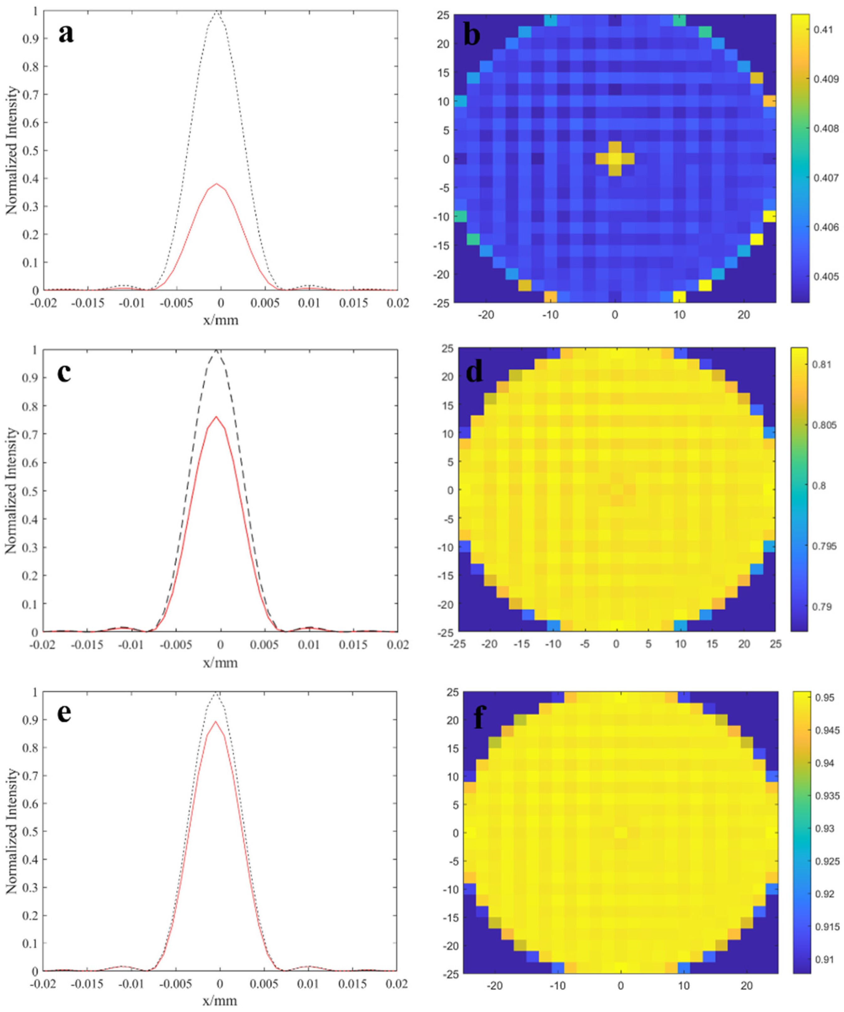
Figure 1. The illustration of eight-level lightweight diffractive lens.
Photonics 12 00086 g001
Figure 2. A schematic diagram of the eight-level lightweight diffractive lens fabrication process.
Photonics 12 00086 g002
Figure 3. Optical structure of the receiver system in laser radar system (The red solid line represents the optical path of the vertically incident receiving system, and the green dashed line represents the non-vertically incident optical path).
Photonics 12 00086 g003
Figure 4. Schematic of the laser radar distance test system.
Photonics 12 00086 g004
Figure 5. Theoretical simulation results of Huygens PSF and diffraction efficiency for (a,b) two−level, (c,d) four−level and (e,f) eight−level diffractive receiving objective lens (The black dash curves represent continuous surface simulations and the red curves represent simulations for two, four, and eight-step structures).
Photonics 12 00086 g005
Figure 6. (a) The picture of eight−level lightweight diffractive lens. (b) The partial structure profilometer test results of eight−level phase profile.
Photonics 12 00086 g006
Figure 7. Photo of the long-distance test system and target.
Photonics 12 00086 g007
Figure 8. The histogram of laser radar echo photon counts distance results of (ac) short-distance ranging experiments. And (d) long-distance ranging experiments.
Photonics 12 00086 g008
Table 1. The parameter of the diffractive lens.
ParameterEight LevelsFour LevelsTwo Levels
Effective aperture (mm)505050
Working wavelength (nm)106410641064
Focus (mm)300300300
Smallest linewidth (μm)1.63.26.4
Etching depth of each level (nm)2905901180
Theoretical diffraction efficiency94.78%80.96%40.53%
Disclaimer/Publisher’s Note: The statements, opinions and data contained in all publications are solely those of the individual author(s) and contributor(s) and not of MDPI and/or the editor(s). MDPI and/or the editor(s) disclaim responsibility for any injury to people or property resulting from any ideas, methods, instructions or products referred to in the content.

