Article

A Detailed Study of a Resonant-Assisted Segmented Cladding Fiber for Large Mode Area Applications

1
Photonics Research Center, School of Optoelectronic Engineering, Guilin University of Electronic Technology, Guilin 541004, China
2
Guangxi Key Laboratory of Optoelectronic Information Processing, School of Optoelectronic Engineering, Guilin University of Electronic Technology, Guilin 541004, China
*
Author to whom correspondence should be addressed.
Photonics 2025, 12(1), 84; https://doi.org/10.3390/photonics12010084
Submission received: 7 December 2024 / Revised: 14 January 2025 / Accepted: 15 January 2025 / Published: 17 January 2025

Abstract

:
In this work, we have proposed and optimized a large mode area segmented cladding fiber (SCF) with an unconventional low-index segment cladding. The low-refractive-index cladding proposed in this paper consists of three parts. There three geometric parameters chosen as design variables were the length and width of the first part and the leg length of the isosceles trapezoid in the second part. To investigate the properties of the proposed SCF, numerical modeling based on the finite element method (FEM) was performed. A high leakage loss ratio (>9000) between the high-order modes (HOMs) and the fundamental mode was achieved at a wavelength of 1310 nm, which is significantly higher than that of conventional SCFs. Additionally, the mode area of the proposed fiber reaches 890 µm2 at a core radius of 20 µm. The bending effects on the SCF were also studied. When the bending radius is greater than 0.3 m, the mode area greater than 880 µm2 and remains stable, and the leakage loss of the least high-order mode (LP11h) exceeds 30 dB/m. The new fiber design demonstrates significant potential for high-power fiber lasers

1. Introduction

Since the development of the world’s first fiber laser by E. Snitzer at the America Optical Corporation in 1961 [1], fiber lasers have assumed an increasingly prominent role in various fields such as optical communications, military applications, and machining processes [2,3]. The demand for higher power levels in fiber lasers has steadily risen, and by 2013, single-mode fiber lasers with continuous output powers of 20 kW had been achieved [4]. As the output power of fiber lasers increases, nonlinear effects and transverse mode instability emerge as significant obstacles hindering the development of high-power fiber lasers [5,6]. Enlarging the mode area of fibers not only raises the threshold for nonlinear effects but also prevents fiber damage that can arise from excessive power density. Maintaining single-mode operation in fibers mitigates transverse mode instability. Furthermore, under bending conditions, modes in the fiber can leak out, leading to a sharp increase in bending losses. Therefore, the development of large mode area fibers that possess both superior single-mode characteristics and bending resistance is essential.
Traditional step-index fibers augment the mode area by enlarging the core diameter and require a low numerical aperture (NA) to ensure single-mode operation. Chemical Vapor Deposition (CVD) methods are widely used in optical fiber preform fabrication [7]. By employing high Yb doping levels, the Modified Chemical Vapor Deposition (MCVD) process can be used to fabricate extremely low NA fibers, with NA as low as 0.025 [8]. In addition to CVD methods, a modified sol-gel method, combined with high-temperature melting and molding technology, has been employed to fabricate optical fibers with a numerical aperture as low as 0.02 [9]. Although significant progress has been made in manufacturing low NA fibers, their production remains challenging. Furthermore, a low NA in an optical fiber leads to a weakened confinement of the mode within the core, making the fiber exceptionally sensitive to bending.
In recent years, to achieve a large mode area and single-mode operation, numerous fiber structures have been conceived, such as photonic crystal fiber [10], multi-trench fiber [11], leakage channel fiber [12], multicore fiber [13], nanostructured core fiber [14], Bragg fiber [15], and segmented cladding fiber [16,17].
The notion of segmented cladding fiber (SCF) was initially proposed by V. Rastogi in 2001 [18]. SCFs are characterized by a uniform high-refractive-index core and a cladding comprising periodically alternating regions of high and low refractive index, arranged angularly along the azimuthal direction. In SCFs, the fundamental mode can achieve low leakage loss while simultaneously ensuring high losses for all higher-order modes. The high leakage losses of HOMs in SCFs effectively suppress them, enabling single-mode operation across a broad wavelength range.
In the SCF fiber design, the large mode field is achieved through mode leakage effects, which eliminates the requirement for an extremely low refractive index contrast between the core and cladding materials to maintain a low NA. Furthermore, in contrast to photonic crystal fibers, SCFs are air-hole-free structures, with enhanced manufacturability compared to complex microstructure fibers [18].
Since their initial proposal in 2001, SCFs have achieved significant advancements in recent years. In the design of SCFs, a series of innovative developments have been documented. In 2016, S. Ma utilized SCF to develop large mode area fibers and analyzed their bending characteristics [16]. Subsequently, in 2018, they introduced a resonant ring into SCF and assessed the influence of the resonant ring on the SCF performance [19]. In 2022, S. Yang proposed SCFs with a parabolic-profile core [20]. Most recently, in 2023, M. Pournoury proposed an SCF consisting of a uniform core and a double cladding, while the inner cladding consisted of a resonant layer of rods surrounded by high-refractive-index rings [21].
On the fabrication front, SCFs can be manufactured using diverse materials, including polymers [22], silica [23], silver halide [24], and chalcogenide glass [25], offering flexibility in material selection to meet specific application and wavelength requirements. In terms of production methodologies, several advanced techniques have been used in SCF manufacturing, including the bicomponent spinning technology [22], the extrude-and-stack technique [25], and the stack-and-draw technique [23,26].
For fiber amplifiers, a typical application scenario of large mode area fibers, the SCF offers an exceptionally broad single-mode operating bandwidth. This allows both the pump light and the signal light to propagate in a single-mode within the core. Additionally, due to the large core size, nonlinear effects are significantly reduced. As a result, doping can be applied to both the core and the high-index cladding segments. In this configuration, both the pump light and the signal light primarily propagate within the core, enabling the use of core-pumping schemes to efficiently amplify the signal light [27,28].
A novel structure of an SCF is introduced in this paper. In contrast to conventional SCFs, the fiber incorporates a resonant effect through the use of an unconventional low-refractive-index segment cladding. We term this type of SCF the resonant-assisted SCF (RA-SCF). It demonstrates outstanding characteristics in both large mode area and single-mode operation. The RA-SCF achieves effective single-mode operation across a broad wavelength range of 1000 to 1800 nm. Suppression of higher-order modes is superior to that of traditional SCFs. Single-mode operation can be maintained with a mode area of 890 μm2 at a wavelength of 1310 nm. For a bending radius exceeding 0.3 m, the fundamental mode area is consistently greater than 880 μm2. The need for controlling the bending orientation is eliminated, as the RA-SCF exhibits high loss of the least high-order modes over a bending orientation range of 0° to 360°. The fiber shows great potential in high power fiber lasers.

2. Analysis Method and Fiber Structure

By modeling the fiber and conducting an analysis using the Finite Element Method (FEM), we are able to obtain core parameters including Mode Area (MA), Leakage Loss (LL), and Loss Ratio (LR).
The MA serves as a critical parameter for large mode area fiber. When a fixed incident power is applied, the larger the MA, the lower the optical power density within the fiber, and therefore, the smaller the nonlinear effects within the fiber. The MA can be mathematically represented as [21]:
M A = E 2 d x d y 2 E 4 d x d y
where E is the transverse electric field distribution.
By implementing a perfectly matched layer (PML) outside the fiber model as a boundary condition, the imaginary part of the fiber’s propagation constant (β) can subsequently be determined. The formula used for calculating LL is given by [19]:
L L = 20 ln 10 I m β = 40 π ln 10 λ I m n n e f f
where neff is the effective refractive index, and λ is the wavelength in a vacuum.
The presence of multiple modes in a fiber can led to mode competition, ultimately resulting in mode instability. The single-mode characteristic of large mode area fiber can be described as follows [29]:
L R = F M l o s s L H O M L o s s
where LR is the ratio between the loss of fundamental mode (FM-loss) and the loss of the least high-order mode (L-HOM-loss). Under the premise of ensuring basic single-mode operation, a higher value of LR signifies enhanced single-mode performance.
Under bending conditions, the stress exerted on the fiber results in changes to the refractive index distribution, which in turn influences the fiber’s modal characteristics. Consequently, an equivalent refractive index method is employed to model the bent fiber as an equivalent straight fiber. Taking into account the elastic-optic effect, the refractive index on the cross section of the bent fiber can be mathematically represented as [30]:
n b e n t x , y = n s t r a i g h t x , y ( 1 + x c o s θ + y s i n θ ρ R )
where nbent and nstraight represent the refractive index profile of the bent fiber and straight fiber, respectively. X and y denote the Cartesian coordinates indicating the bending orientation, while θ signifies the angle between the bending direction and the positive direction of the x-axis. R signifies the bending radius of the fiber, and ρ denotes the optical elastic coefficient, which has been established as 1.25.
Figure 1 presents the schematic cross-sectional layout of the RA-SCF structure. The yellow-colored region, which encompasses the core, exhibits a refractive index of ncore = 1.450. Conversely, the white-colored region signifies the fiber cladding with a lower refractive index (nclad) of 1.444. Unlike conventional SCF, where the low-refractive-index region is shaped like an isosceles trapezoid, the low-refractive-index cladding presented in this study is comprised of three distinct sections. The first part (P1) consists of a semicircle with a rectangle. Both the diameter of the semicircle and the height of the rectangle are L1, while the length of the rectangle is L2. The second section (P2) is shaped as an isosceles trapezoid. Its upper base, which is contiguous with P1, has a length equivalent to L1. The lengths of its legs are L3, and the angle formed between the legs and the perpendicular to the bases is θ. The third section (P3) combines a rectangle with a curved region.
Figure 2 illustrates the mesh used for calculating the SCF fiber using the FEM. The mesh comprises 5440 elements with an average element quality of 0.82 and possesses 38,265 degrees of freedom. Due to the alternating distribution of high and low refractive index materials within the cladding of the SCF, which results in an inhomogeneous refractive index profile, the refractive index of the PML on the outer side of the cladding is similarly configured to alternate between high and low refractive index materials. The thickness of the PML is set to 10 µm.

3. Results and Discussion

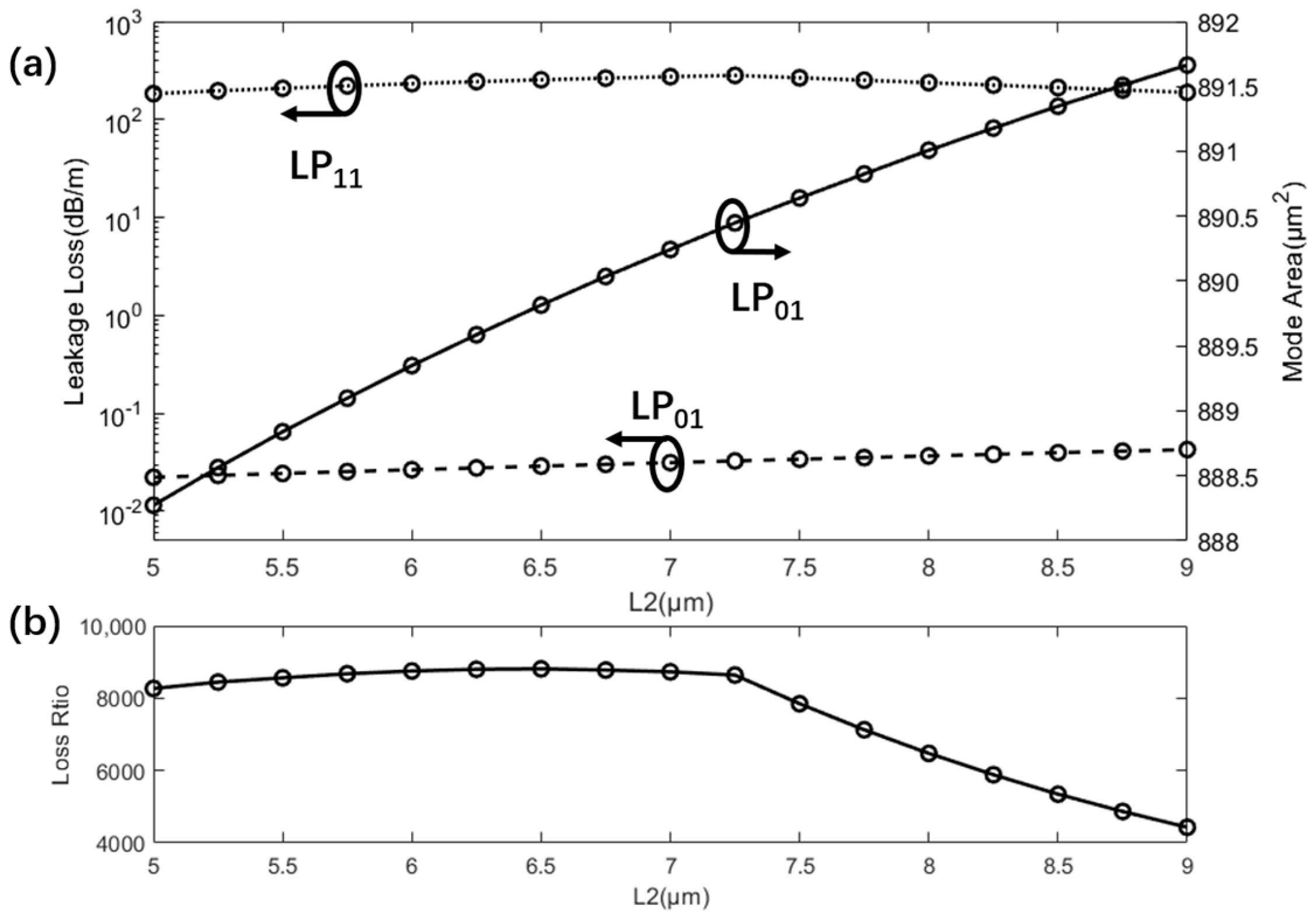
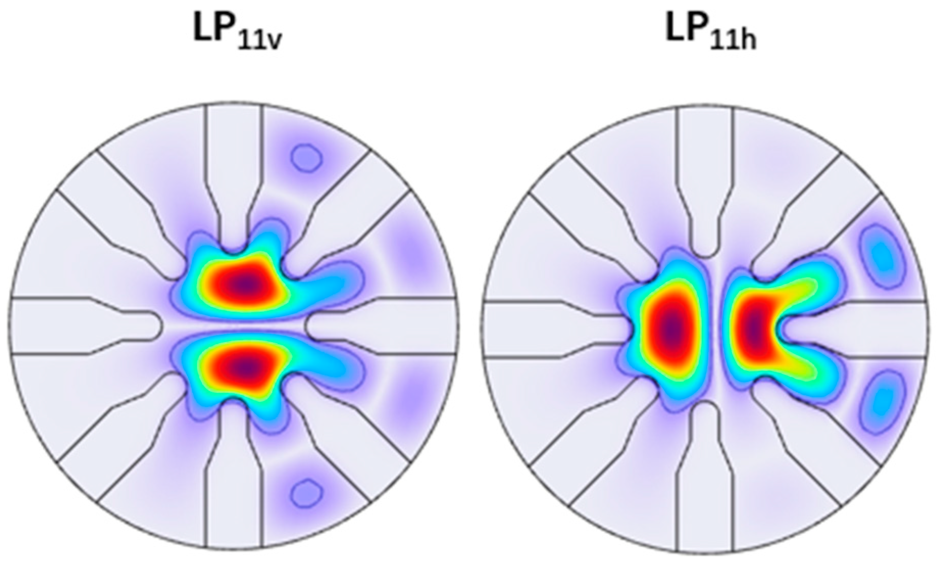
3.1. Properties of the RA-SCF

As indicated in Table 1, the radius of the RA-SCF is 62.5 μm, with a core radius of 20 μm, and the other initial parameters are listed in Table 1. To investigate the properties of the RA-SCF, numerical modeling based on the FEM has been conducted. Figure 3 shows the computed electric field profile for the fundamental mode (LP01) and the least high-order mode (LP11), using the parameters outlined in Table 1. The mode area of the LP01 mode is 890 μm2, and the leakage losses of LP01 and LP11 modes are 0.03 dB/m and 273.78 dB/m, respectively.
The influence of the wavelength on the single-mode performance of the RA-SCF has been investigated and presented in Figure 4. As shown in Figure 4, using the parameters outlined in Table 1, within the wavelength spectrum range of 1000 nm to 1800 nm, the leakage loss of LP01 and LP11 modes, as well as the mode area of LP01, increase with the increasing of wavelength. Specifically, the leakage loss for the LP01 mode ranges from 0.01 dB/m to 0.14 dB/m, while for the LP11 mode, it spans from 170 dB/m to 388 dB/m. The loss ratio, which ranges from 2771 to 17,000, exhibits a decreasing trend as the wavelength increases. The mode area of LP01 varies from 845 μm2 to 968 μm2. Based on the data, it is evident that the RA-SCF possesses relatively excellent transmission properties and single-mode maintenance characteristics across the wavelength range of 1000 nm to 1800 nm.
To gain a deeper understanding of the RA-SCF, we utilize the parameters listed in Table 1 as a foundation and investigate the implications of structural modifications on the transmission characteristics of the SCF. The effects of diverse structural parameters have been examined and are summarized in Figure 5, Figure 6 and Figure 7.
Figure 5 illustrates the influence of parameter L1 on the single-mode performance of the RA-SCF. For the given design parameters, when L1 varies within the range of 6–10 μm, the mode area and the leakage loss of the LP01 mode decrease as L1 increases. This is attributed to the enhancement in the effective refractive index contrast between the core and the cladding as L1 increases. The leakage loss of the LP11 does not decrease monotonically with the increase in L1. Consequently, the loss ratio exhibits a similar trend, reaching a peak value of 9094 when L1 equals 8.25 μm.
Figure 6 depicts the variation of the mode area of the LP01 mode and the leakage losses of the LP01 and LP11 modes of the RA-SCF with respect to the parameter L2. As the value of L2 increases, the effective refractive index contrast between the core and the cladding decreases, leading to a corresponding increase in the mode area and the leakage loss of the LP01 mode. The leakage loss of the LP11 initially increases and then decreases with the increase in L2. From Figure 6, it is evident that the effect of L2 on the performance on the RA-SCF is less significant than that of L1.
The effect of parameter L3 is presented in Figure 7. Similar to parameter L1, as L3 increases, the mode area and the leakage loss of the LP01 decrease, and leakage loss of the LP11 initially increases and then decreases. It can be observed from Figure 7 that the impact of L3 on the mode area and the leakage loss of the LP01 is substantially less than that of L1. Due to the resonance effect, L3 has a notable impact on the leakage loss of the LP11 mode, resulting in greater fluctuations in the loss ratio.

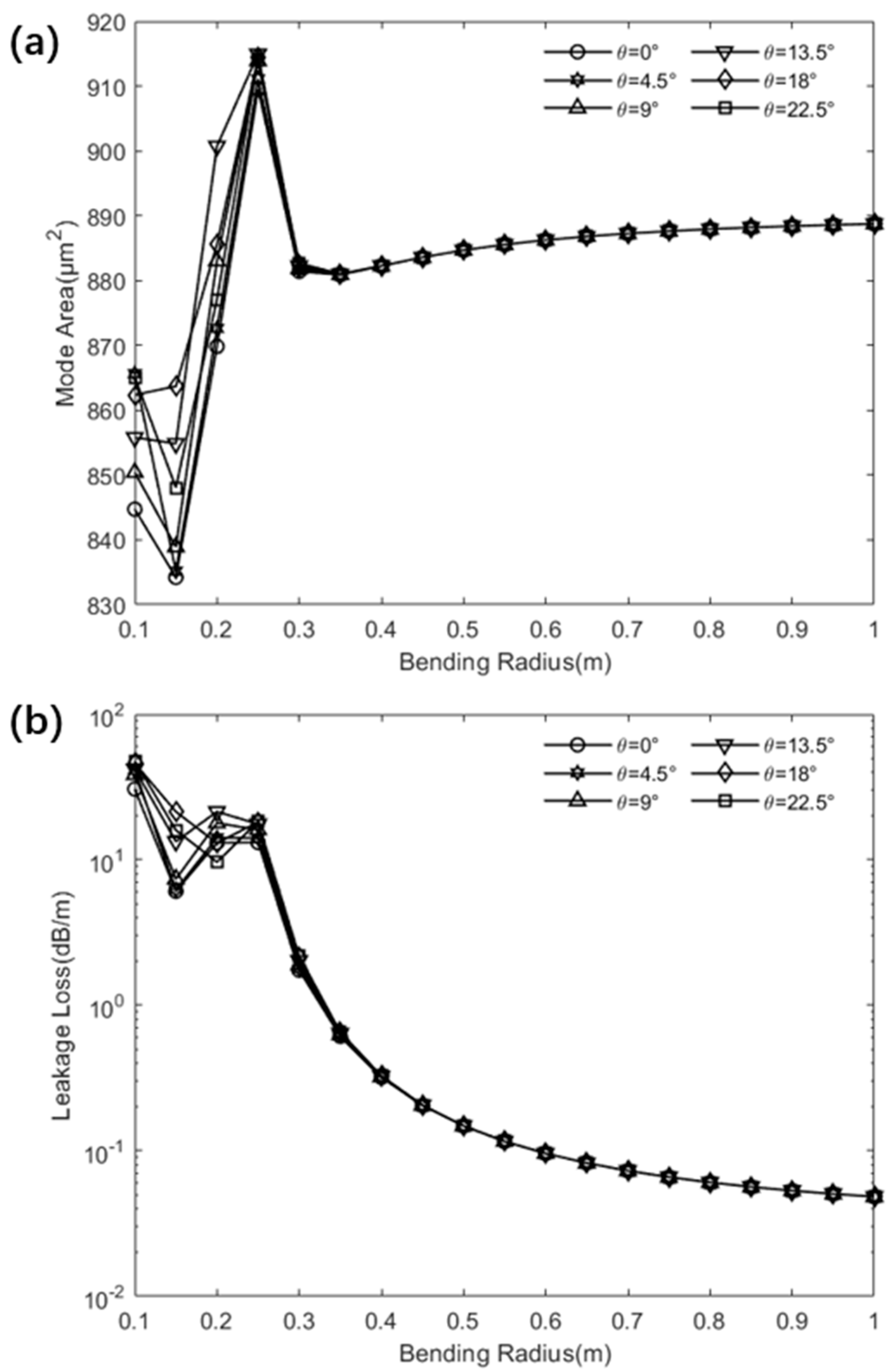
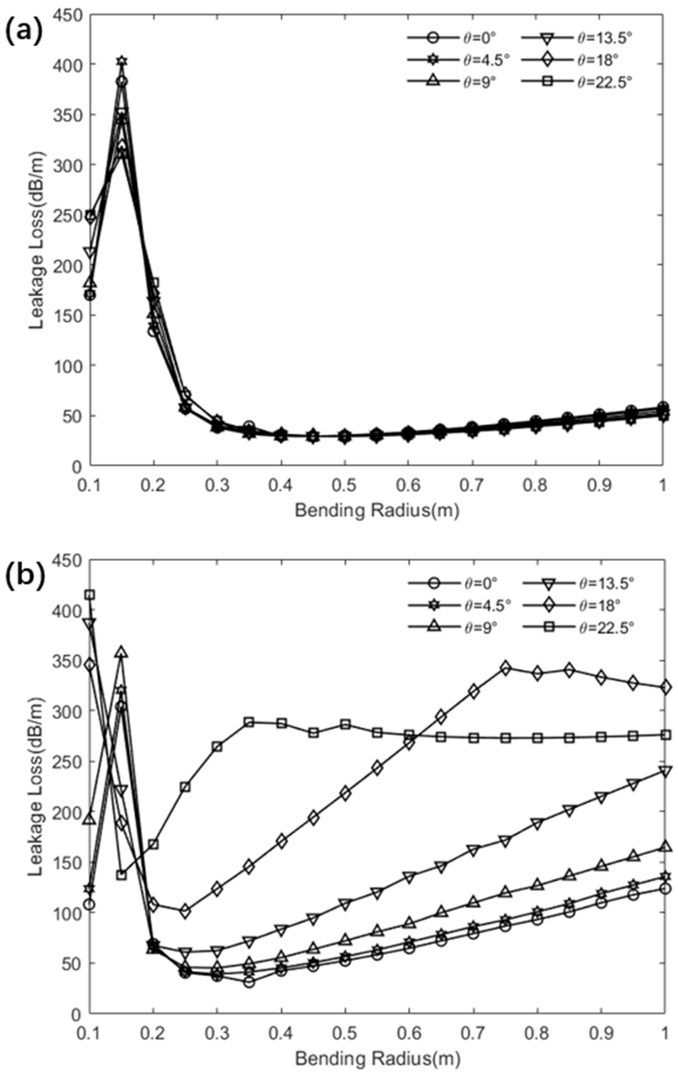
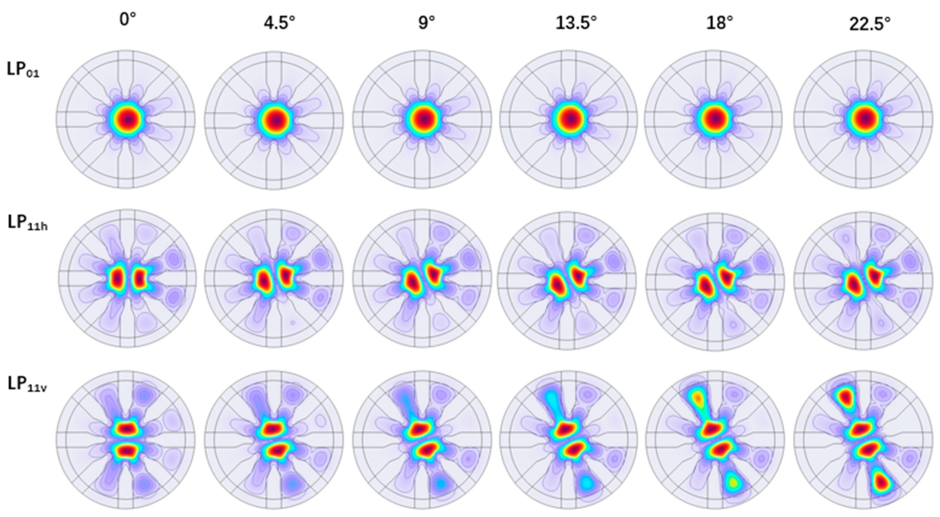
3.2. Bending Performance of the RA-SCF

In a curved optical fiber, the symmetry of the refractive index distribution is disrupted. As illustrated in Figure 8, the orthogonal polarization modes within the fiber are no longer degenerate. Consequently, when examining the bending characteristics of optical fibers, it is imperative to undertake individual analyses for the two orthogonal polarization modes LP11v and LP11h. In an SCF, owing to the periodic distribution of the material’s refractive index, the influence of various bending orientations on the fiber’s bending behavior also necessitates scrutiny. The impact of bending has been studied using the parameters listed in Table 1 and is presented in Figure 9 and Figure 10.
The impact of bending on the fundamental mode LP01 is illustrated in Figure 9. As depicted in Figure 9a, when the bending radius ranges from 0.1 to 0.3 m, the mode area undergoes oscillations, dependent on the bending orientation. For a bending radius of 0.35 to 1 m, the mode area increases gradually as the bending radius increases, expanding from 881 μm2 to 889 μm2, which approximates to the mode area in the unbent condition. Within this bending range, the influence of the bending orientation on the mode area is negligible. Figure 9b demonstrates the influence of bending on the leakage loss of the LP01 mode. Analogous to the effect of bending radius on the mode area, when the bending radius is small, the leakage loss exhibits oscillations that are dependent on the bending orientation. Once the bending radius surpasses 0.25 m, the impact of the bending orientation on leakage loss becomes insignificant. As the bending radius increases from 0.25 m to 1 m, the leakage loss decreases from 18 dB/m to 0.05 dB/m.
Figure 10 illustrates the impact of bending on the LP11. As previously mentioned, the effect of bending on the LP11 mode requires separate analysis for both the LP11h and LP11v polarization states. Analogous to LP01, when the bending radius is small, the leakage loss of both LP11h and LP11v exhibits oscillations that are contingent upon the bending orientation. Specifically, within a bending radius range of 0.25 to 1 m, as the bending radius increases, the leakage loss of the LP11h mode rises, with the magnitude of increase being dependent upon the bending orientation. In contrast, for the LP11v mode, the trend of mode loss with an increasing bending radius varies considerably based on the bending orientation. Specifically, when the bending orientation is within the range of 0° to 13.5°, the leakage loss intensifies as the bending radius increases, and the rate of increase accelerates as the bending orientation increases. Alternatively, when the bending orientations are set at 18° and 22.5°, the loss of the LP11v mode exhibits an initial rapid increase with the growing bending radius, followed by a stabilization phase where further changes become negligible. Notably, at a bending orientation of 22.5° and a bending radius of 1 m, the mode loss of the LP11v mode is 276 dB/m, which approximates to the leakage loss in the unbent condition.
Figure 11 illustrates the electric field distributions of the LP01, LP11v, and LP11h modes in the RA-SCF with a bending radius of r = 0.4 m under varying bending orientations θ. As depicted in the figure, as the bending orientation shifts from 0° to 22.5°, the electric field of the LP11v mode progressively extends from the core region into the cladding, leading to a consequent rise in the leakage loss associated with the LP11v mode.
Compared to traditional SCFs, RA-SCF features a modified cladding structure where the boundary between the high-refractive-index regions and the low-refractive-index regions is no longer a straight line. The segmented boundary introduces a resonant effect, leading to a substantial improvement in the SCF’s performance. As illustrated in Table 2, when the FM-loss differences are very small, the L-HOM-loss of the RA-SCF reaches 9094, demonstrating a significant enhancement compared to both conventional SCF (89) and RR-SCF (2393). Consequently, RA-SCF can achieve a higher loss ratio. Under bending conditions with a core radius of 20 μm, the RA-SCF demonstrates a loss ratio of 50 and a mode area of 881 μm2 at a bending radius of 0.35 m, while the traditional SCF shows a lower loss ratio of 30 and a smaller mode area of 754 μm2 at a bending radius of 0.15 m [16]. This indicates that the single-mode performance of RA-SCF is significantly enhanced compared to traditional SCF and RR-SCF.
Finally, from a manufacturing perspective, RA-SCF structures can be fabricated using either the extrude-and-draw technique [25] or the stack-and-draw technique [23,26]. Moreover, RA-SCFs are all solid structure; issues caused by air holes do not need to be considered during the manufacturing process, which are encountered in photonic crystal fibers and leakage channel fibers.

4. Conclusions

In summary, a novel design of an SCF, characterized by an unconventional low-index segment cladding, has been introduced and analyzed using the FEM in this paper. The influences of diverse fiber structural parameters have been investigated in detail. Due to the resonant effects introduced by the irregular low-index cladding structure, the mode area can achieve 890 μm2, while the leakage loss of the least high-order mode (LP11) achieves a notable level of 273.78 dB/m, accompanied by a loss ratio of 9094. Furthermore, the impact of bending on the SCF’s performance has been investigated. When the bending radius is greater than 0.35 m, the mode area is greater than 880 μm2 and remains stable, and the leakage loss of the least high-order mode (LP11h) surpasses 30 dB/m, with the loss ratio greater than 50. Our research results reveal that the proposed SCF structure exhibits excellent single-mode maintenance characteristics both in the bent and unbent condition.

Author Contributions

Conceptualization, methodology, software, writing—original draft preparation, M.X.; software, H.Q.; methodology, S.L.; validation, Y.H.; review and editing, L.Y. All authors have read and agreed to the published version of the manuscript.

Funding

This research was funded by the Guangxi Science and Technology Program Projects AD21220078.

Institutional Review Board Statement

Not applicable.

Informed Consent Statement

Not applicable.

Data Availability Statement

Dataset available on request from the authors.

Conflicts of Interest

The authors declare no conflicts of interest.

References

  1. Snitzer, E. Optical maser action of Nd+3 in a barium crown glass. Phys. Rev. Lett. 1961, 7, 444–446. [Google Scholar] [CrossRef]
  2. Coffey, V. High-energy lasers: New advances in defense applications. Opt. Photonics News 2014, 25, 28–35. [Google Scholar] [CrossRef]
  3. Shi, W.; Schulzgen, A.; Amezcua, R.; Zhu, X.; Alam, S.-U. Fiber lasers and their applications: Introduction. J. Opt. Soc. Am. B 2017, 34, FLA1. [Google Scholar] [CrossRef]
  4. Shiner, B. The impact of fiber laser technology on the world wide material processing market. In Proceedings of the Conference on Lasers and Electro-Optics 2013, San Jose, CA, USA, 9–14 June 2013; Optical Society of America: Washington, DC, USA; p. AF2J.1. [Google Scholar]
  5. Dawson, J.W.; Messerly, M.J.; Beach, R.J.; Shverdin, M.Y.; Stappaerts, E.A.; Sridharan, A.K.; Pax, P.H.; Heebner, J.E.; Siders, C.W.; Barty, C. Analysis of the scalability of diffraction-limited fiber lasers and amplifiers to high average power. Opt. Express 2008, 16, 13240–13266. [Google Scholar] [CrossRef]
  6. Smith, A.V.; Smith, J.J. Mode instability in high power fiber amplifiers. Opt. Express 2011, 19, 10180–10192. [Google Scholar] [CrossRef] [PubMed]
  7. Jain, D.; Jung, Y.; Barua, P.; Alam, S.; Sahu, J.K. Demonstration of ultra-low NA rare-earth doped step index fiber for applications in high power fiber lasers. Opt. Express 2015, 23, 7407–7415. [Google Scholar] [CrossRef] [PubMed]
  8. Petit, V.; Tumminelli, R.P.; Minelly, J.D.; Khitrov, V. Extremely low NA Yb doped preforms (<0.03) fabricated by MCVD. In Fiber Lasers XIII: Technology, Systems, and Applications; SPIE: Bellingham, WA, USA, 2016; Volume 9728. [Google Scholar]
  9. Wang, S.; Xu, W.; Wang, F.; Lou, F.; Zhang, L.; Zhou, Q.; Chen, D.; Feng, S.; Wang, M.; Yu, C.; et al. Yb3+-doped silica glass rod with high optical quality and low optical attenuation prepared by modified sol-gel technology for large mode area fiber. Opt. Mater. Express 2017, 7, 2012–2022. [Google Scholar] [CrossRef]
  10. Knight, J.C.; Birks, T.A.; Cregan, R.F.; Russell, P.S.J.; De Sandro, J.P. Large Mode Area Photonic Crystal Fiber. Opt. Photonics News 1998, 9, 34–35. [Google Scholar] [CrossRef]
  11. Jain, D.; Baskiotis, C.; Sahu, J.K. Mode area scaling with multi-trench rod-type fibers. Opt. Express 2013, 21, 1448–1455. [Google Scholar] [CrossRef]
  12. Dong, L.; Peng, X.; Li, J. Leakage channel optical fibers with large effective area. Opt. Soc. Am. B 2007, 24, 1689–1697. [Google Scholar] [CrossRef]
  13. Becker, M.; Lorenz, A.; Elsmann, T.; Latka, I.; Schwuchow, A.; Dochow, S.; Spittel, R.; Kobelke, J.; Bierlich, J.; Schuster, K.; et al. Single-mode multi-core fibers with integrated Bragg filters. Light. Technol. 2016, 34, 4572–4578. [Google Scholar] [CrossRef]
  14. Franczyk, M.; Pysz, D.; Pucko, P.; Michalik, D.; Biduś, M.; Dłubek, M.; Buczyński, R. Yb3+ doped silica nanostructured core fiber laser. Opt. Express 2019, 27, 35108–35119. [Google Scholar] [CrossRef]
  15. Baskiotis, C.; Molin, D.; Bouwmans, G.; Gooijer, F.; Sillard, P.; Quiquempois, Y.; Douay, M. Bending behaviors of all solid silica large mode area Bragg fibers. In Fiber Lasers VI: Technology, Systems, and Applications; SPIE: Bellingham, WA, USA, 2009; Volume 7195, p. 719520. [Google Scholar]
  16. Ma, S.; Ning, T.; Li, J.; Pei, L.; Zhang, C.; Wen, X. Detailed study of bending effects in large mode area segmented cladding fibers. Appl. Opt. 2016, 55, 9954–9960. [Google Scholar] [CrossRef]
  17. Yu-Lai, S.; De-Jian, Z.; Xiao-Yong, C.; Jia-Ming, N. Bend-resistant low bending loss and large mode area single-mode fiber with low NA. Opt. Fiber Technol. 2019, 51, 101–106. [Google Scholar] [CrossRef]
  18. Rastogi, V.; Chiang, K.S. Propagation characteristics of a segmented cladding fiber. Opt. Lett. 2001, 26, 491–493. [Google Scholar] [CrossRef]
  19. Ma, S.; Ning, T.; Lu, S.; Zheng, J.; Li, J.; Pei, L. Bending-Resistant Design of a Large Mode Area Segmented Cladding Fiber with Resonant Ring. J. Light. Technol. 2018, 36, 2844–2849. [Google Scholar] [CrossRef]
  20. Yang, S.; Zhang, W.; She, Y.; Du, H.; Tu, S. A Large Mode Area Parabolic-Profile Core Fiber with Modified Segmented in Cladding. Photonics 2022, 9, 783. [Google Scholar] [CrossRef]
  21. Pournoury, M.; Zamiri, A.; Ghasemi, M.; Kim, D. The Optimization of a Segmented Cladding Fiber via the Response Surface Methodology Approach for a Large Mode Area. Photonics 2023, 10, 935. [Google Scholar] [CrossRef]
  22. Duan, J.; Teng, C.; Han, K.; Yu, M.; Wu, W.; Zhang, Q.; Chiang, K.S. Fabrication of segmented cladding fiber by bicomponent spinning. Polym. Eng. Sci. 2009, 49, 1865–1870. [Google Scholar] [CrossRef]
  23. Hooda, B.; Pal, A.; Rastogi, V.; Sen, R.; Gandhi, J.; Kobelke, J. Segmented cladding fiber fabricated in silica-based glass. Opt. Eng. 2015, 54, 075103. [Google Scholar] [CrossRef]
  24. Millo, A.; Naeh, I.; Katzir, A. Single-Mode Segmented Cladding Fibers for the Middle Infrared. Light. Technol. 2007, 25, 2115–2121. [Google Scholar] [CrossRef]
  25. Pournoury, M.; Han, S.R.; Ghasemi, M.; Lee, H.; Kim, D.; Oh, K. Silica Segmented Cladding Fiber Design and Its Fabrication Using a Powder-in-Tube Technique. Light. Technol. 2021, 39, 7251–7258. [Google Scholar] [CrossRef]
  26. Peng, Q.; Sheng, J.; Yang, K.; Wang, X.; Sun, W.; Wang, Y.; Liang, X.; Jiao, K.; Bai, S.; Zhao, Z.; et al. Single-Mode Segmented Cladding Chalcogenide Glass Fiber with Ultra-Large Mode Area. Light. Technol. 2023, 41, 5722–5728. [Google Scholar] [CrossRef]
  27. Yang, J.; Ming, H.; Chiang, K.S. Analysis of Erbium-Doped Ultralarge-Core Segmented-Cladding Fibers for Optical Amplification. Light. Technol. 2008, 26, 3098–3103. [Google Scholar] [CrossRef]
  28. Gao, K.; Yang, J.; Wang, A.; Ming, H.; Chiang, K.S. Numerical analysis of high power ytterbium-doped segmented-cladding fiber amplifier. In Proceedings of the Photonics and Optoelectronics Meetings, Wuhan, China, 24–27 November 2008. [Google Scholar]
  29. Wang, Y.; Hou, S.; Xie, G.Y.Z. Bend-resistant stress-type segmented cladding large-mode-area single-mode fibers. Appl. Opt. 2023, 62, 2218–2226. [Google Scholar] [CrossRef]
  30. Ma, S.; Ning, T.; Pei, L.; Li, J.; Zheng, J. Bend-resistant large mode area fiber with novel segmented cladding. Opt. Laser Technol. 2018, 98, 113–120. [Google Scholar] [CrossRef]
Figure 1. Schematic cross-section of the RA-SCF structure. White and yellow colors represent the low- and high-refractive-index regions, respectively.
Photonics 12 00084 g001
Figure 2. Finite element mesh configuration employed for numerical simulation of RA-SCF. Blue and gray colors represent the high- and low-refractive-index regions, respectively.
Photonics 12 00084 g002
Figure 3. The surface profile of the transverse electric field component of the LP01 and LP11 of the RA-SCF.
Photonics 12 00084 g003
Figure 4. (a) Variation of the leakage losses of LP01 and LP11 modes and the mode area of LP01 with wavelength. (b) Variation of the loss ratio with wavelength.
Photonics 12 00084 g004
Figure 5. (a) Variation of the leakage losses of LP01 and LP11 modes and the mode area of LP01 with L1. (b) Variation of the loss ratio with L1.
Photonics 12 00084 g005
Figure 6. (a) Variation of the leakage losses of LP01 and LP11 modes, and the mode area of LP01 with L2. (b) Variation of the loss ratio with L2.
Photonics 12 00084 g006
Figure 7. (a) Variation of the leakage losses of LP01 and LP11 modes, and the mode area of LP01 with L3. (b) Variation of the loss ratio with L3.
Photonics 12 00084 g007
Figure 8. Surface profile of the transverse electric field component of the LP11v, and LP11h of the RA-SCF with bending radius R = 0.2 m and bending orientation θ = 0°.
Photonics 12 00084 g008
Figure 9. (a) Variation of the mode area of LP01 with bending radius for different bending orientations θ. (b) Variation of the leakage loss of LP01 with bending radius for different bending orientations θ.
Photonics 12 00084 g009
Figure 10. (a) Variation of the leakage loss of LP11h with bending radius for different bending orientations θ. (b) Variation of the leakage loss of LP11v with bending radius for different bending orientations θ.
Photonics 12 00084 g010
Figure 11. The electric field of the LP01, LP11v, and LP11h modes of the RA-SCF with bending radius r = 0.4 m for different bending orientations θ.
Photonics 12 00084 g011
Table 1. The initial simulation parameters of the RA-SCF.
ParameterValue
rf62.5 μm
rc20 μm
φ45°
L18 μm
L27 μm
L310 μm
θ22.5°
nclad1.444
ncore1.450
λ1310 nm
Table 2. Comparison of RA-SCF with traditional SCF and RR-SCF.
Core Radius
(μm)
Wavelength
(nm)
FM-loss
(dB)
L-HOM-Loss (dB)Loss Ratio
Traditional SCF [16,19]1510640.0151.3589
RR-SCF [19]1610640.02866.22393
RA-SCF2013100.027244.69094
Disclaimer/Publisher’s Note: The statements, opinions and data contained in all publications are solely those of the individual author(s) and contributor(s) and not of MDPI and/or the editor(s). MDPI and/or the editor(s) disclaim responsibility for any injury to people or property resulting from any ideas, methods, instructions or products referred to in the content.

