Design Method of Infrared Stealth Film Based on Deep Reinforcement Learning


Abstract
1. Introduction
2. Model and Method
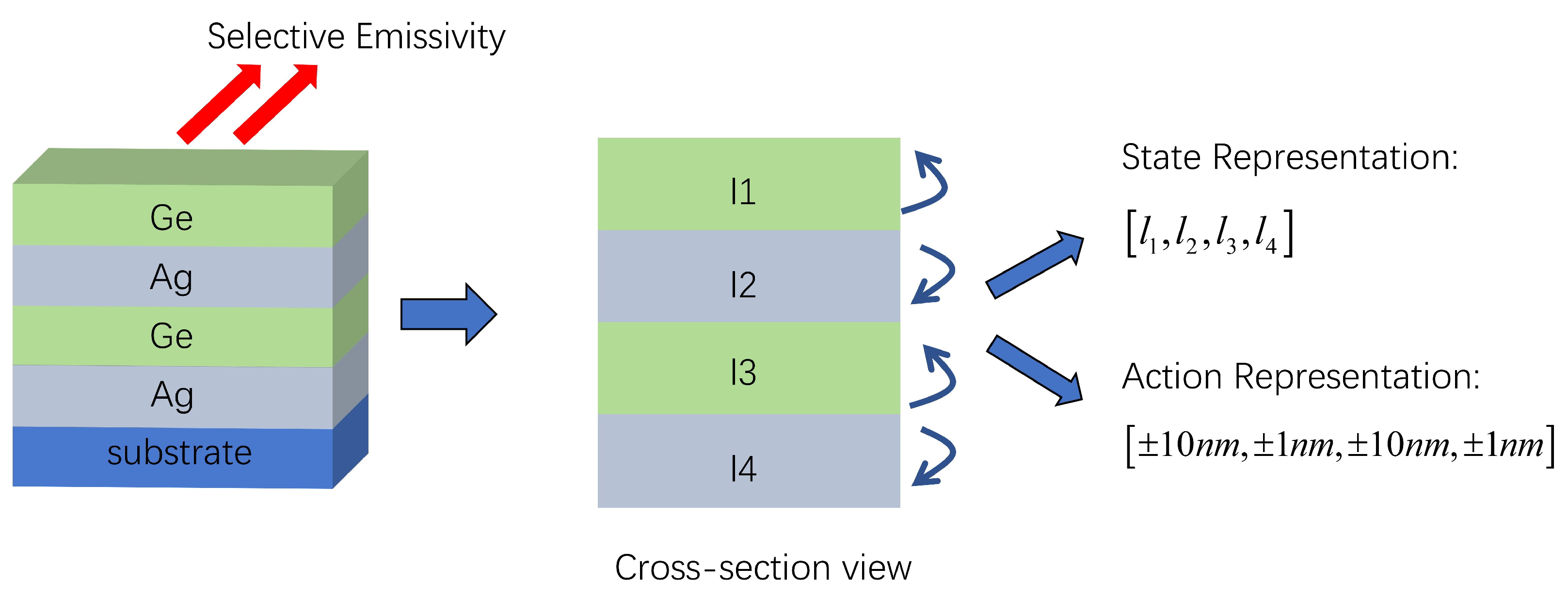
2.1. Setting Up the Design Environment
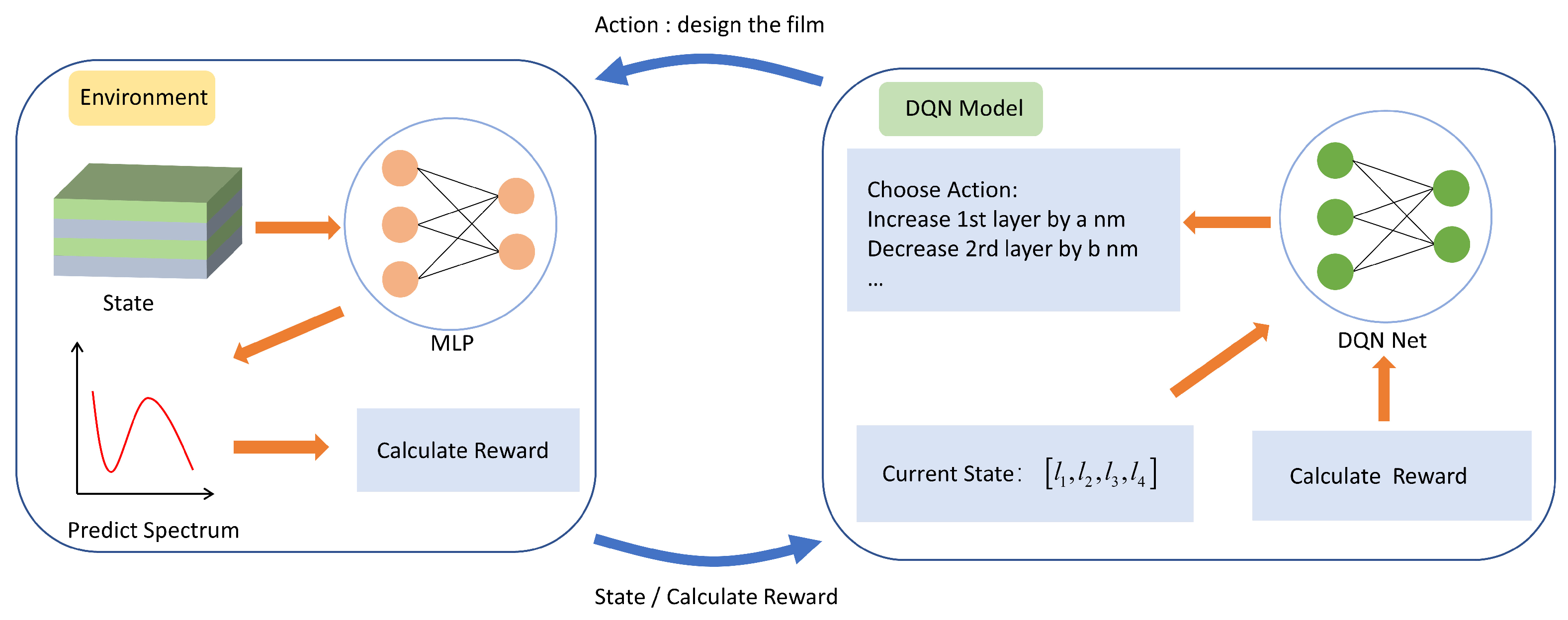
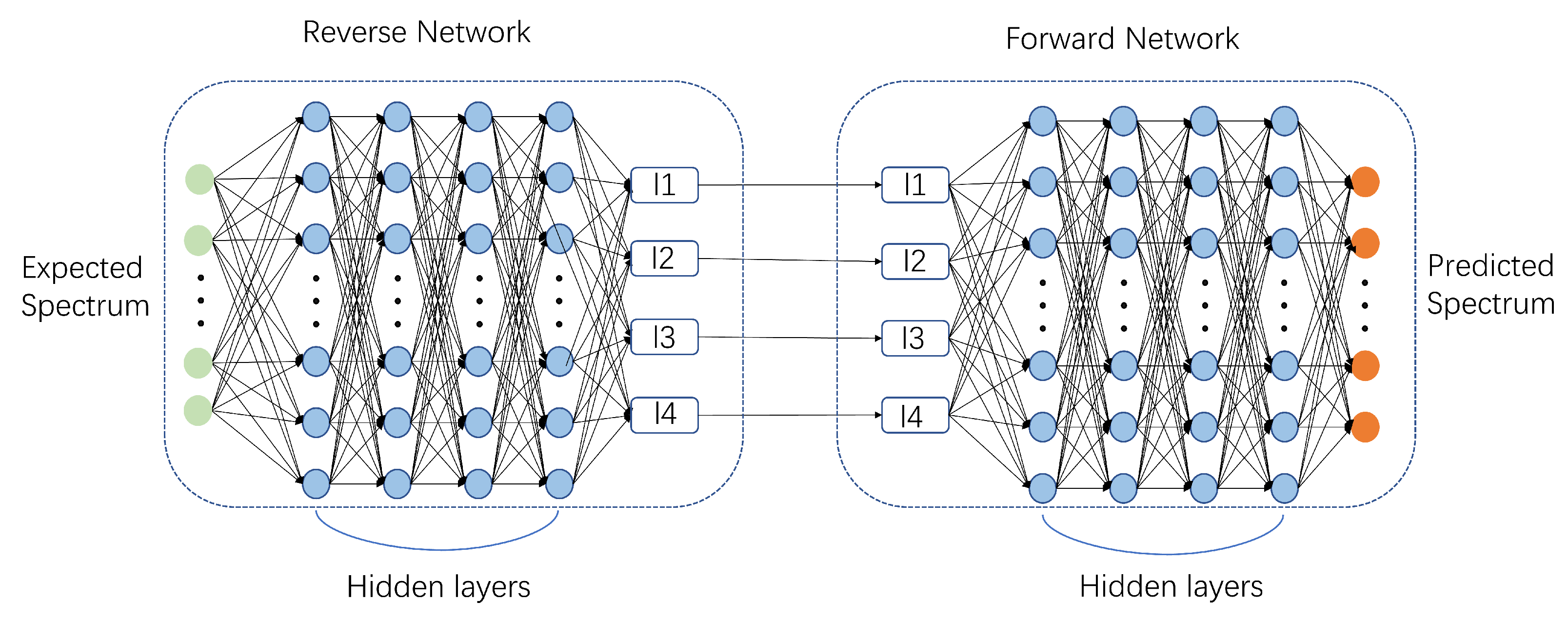
2.2. DQN Design Process
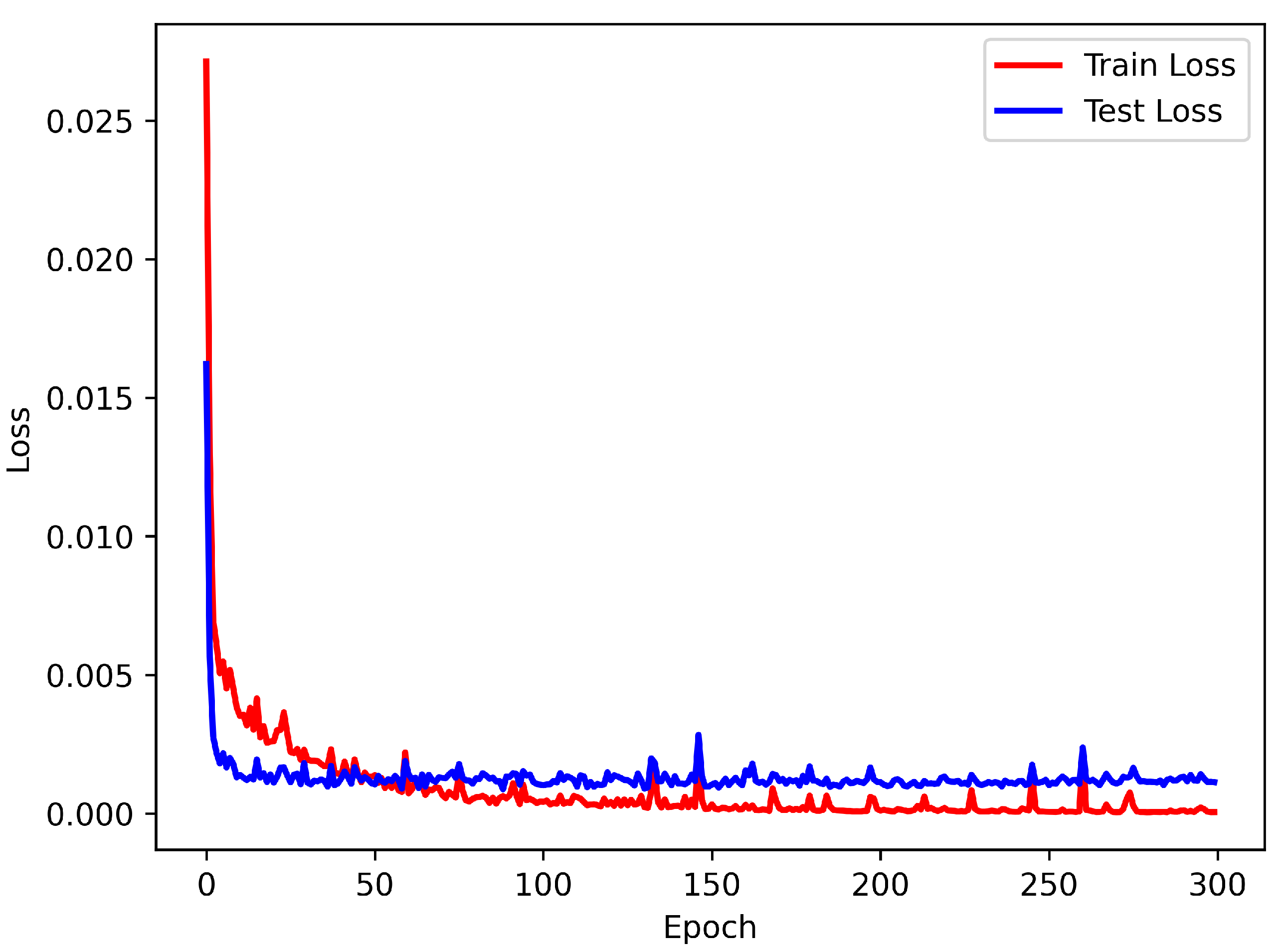
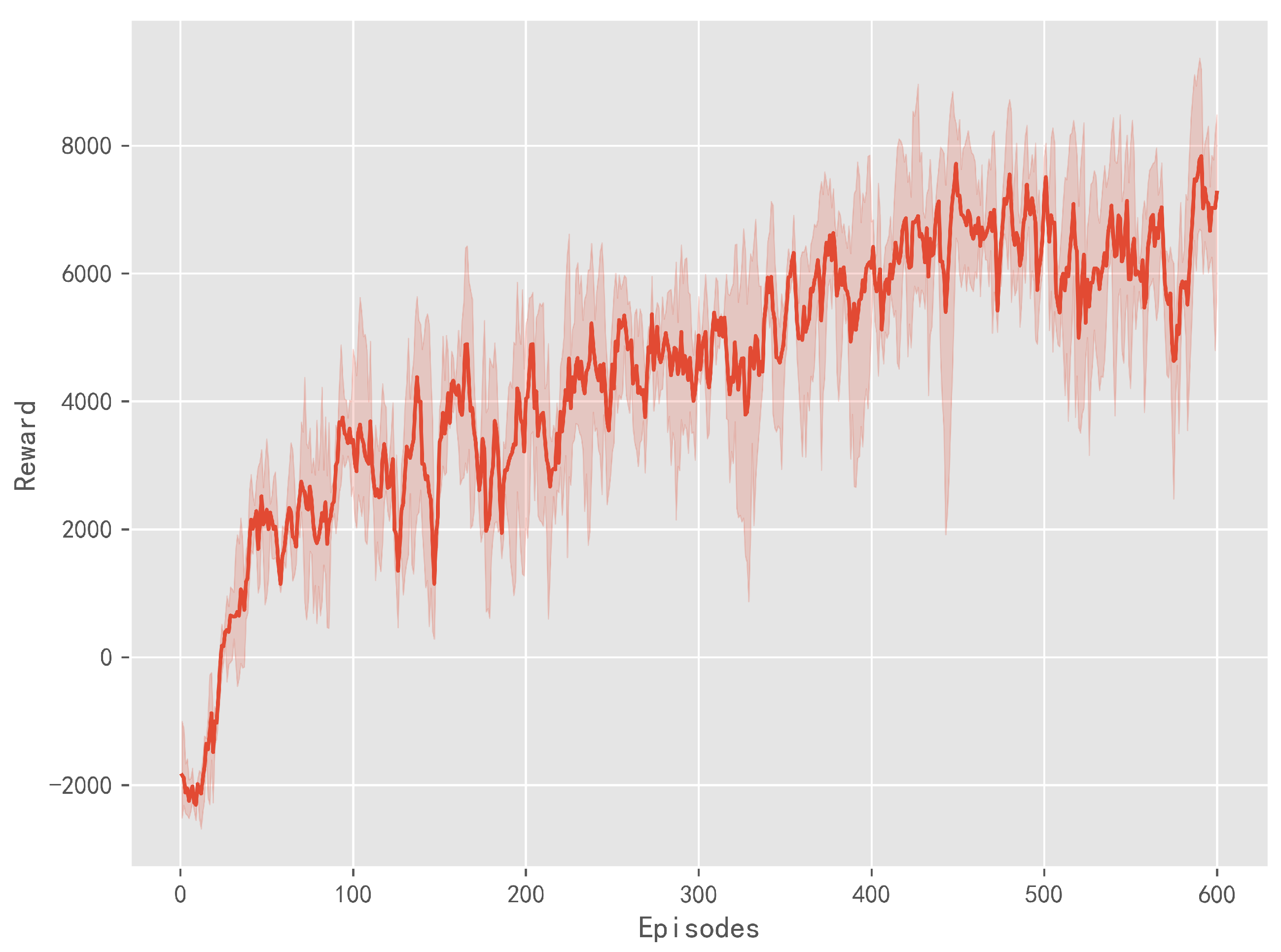
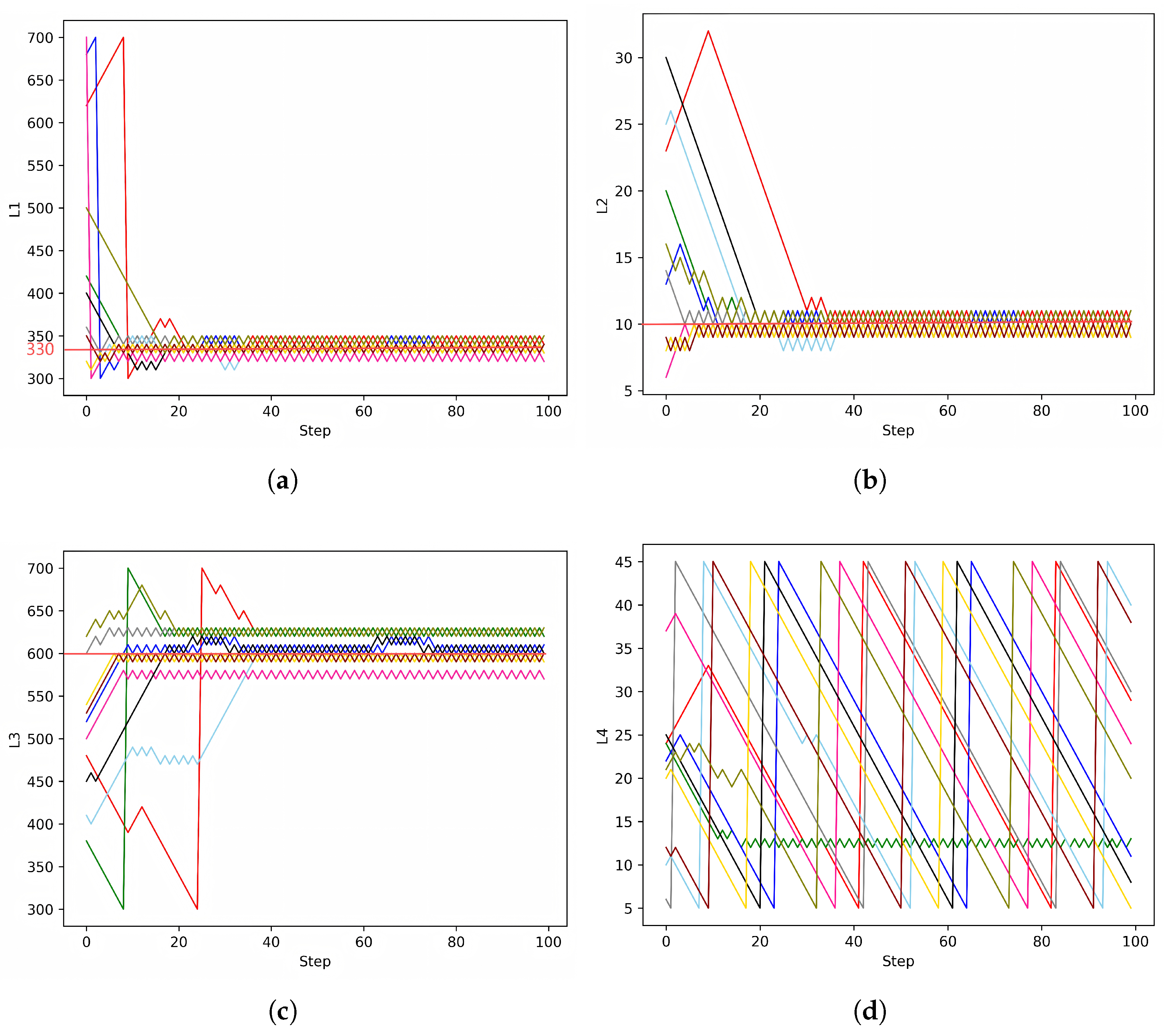
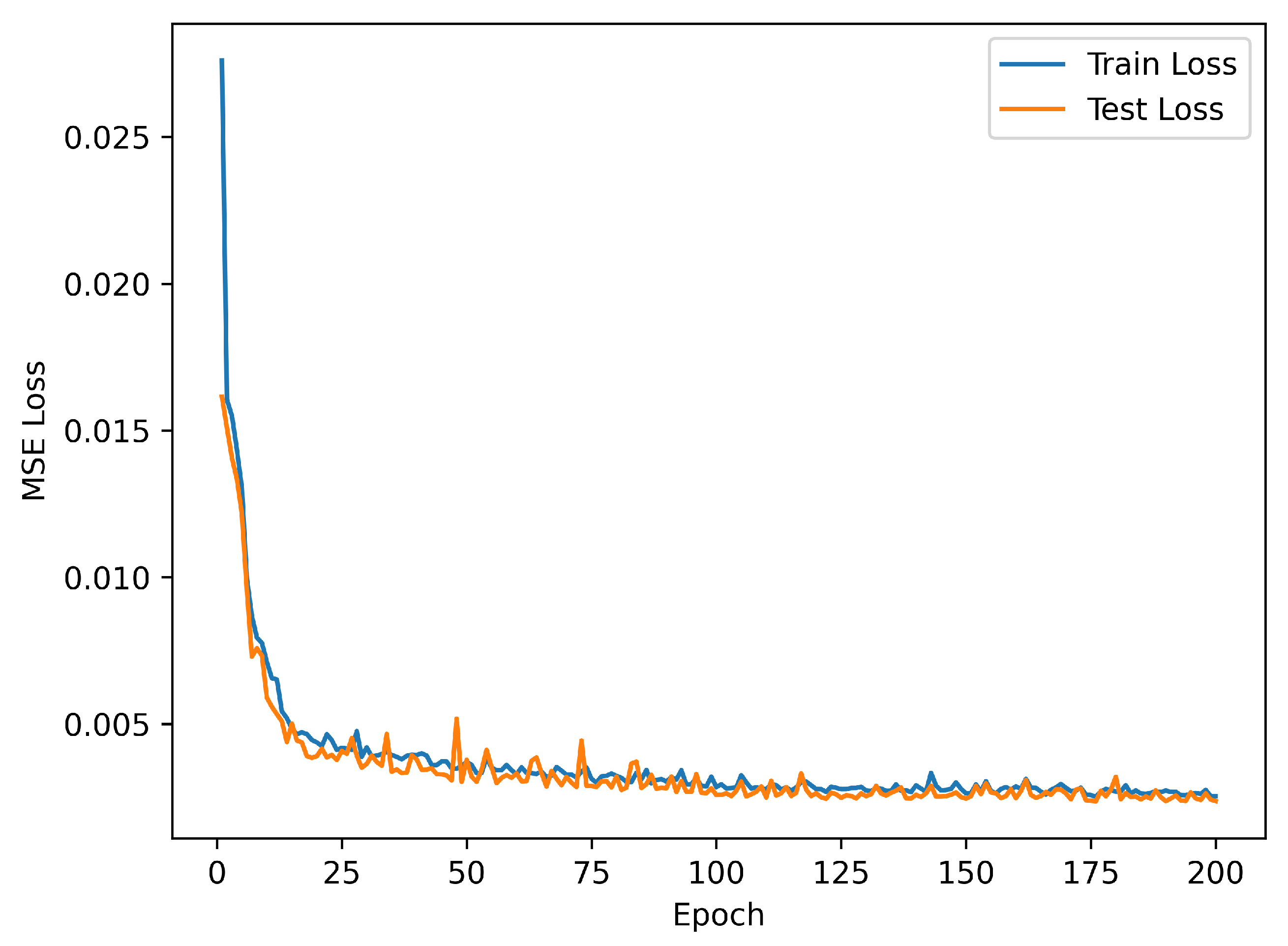
2.3. Training Process
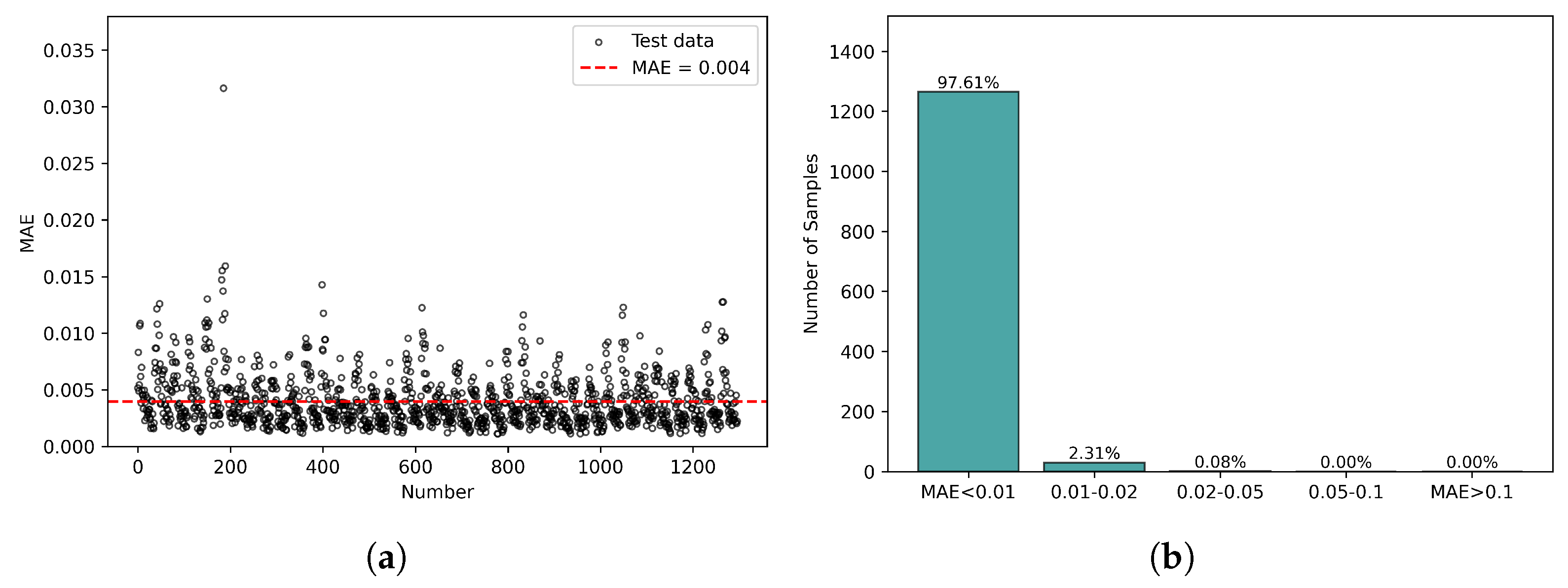
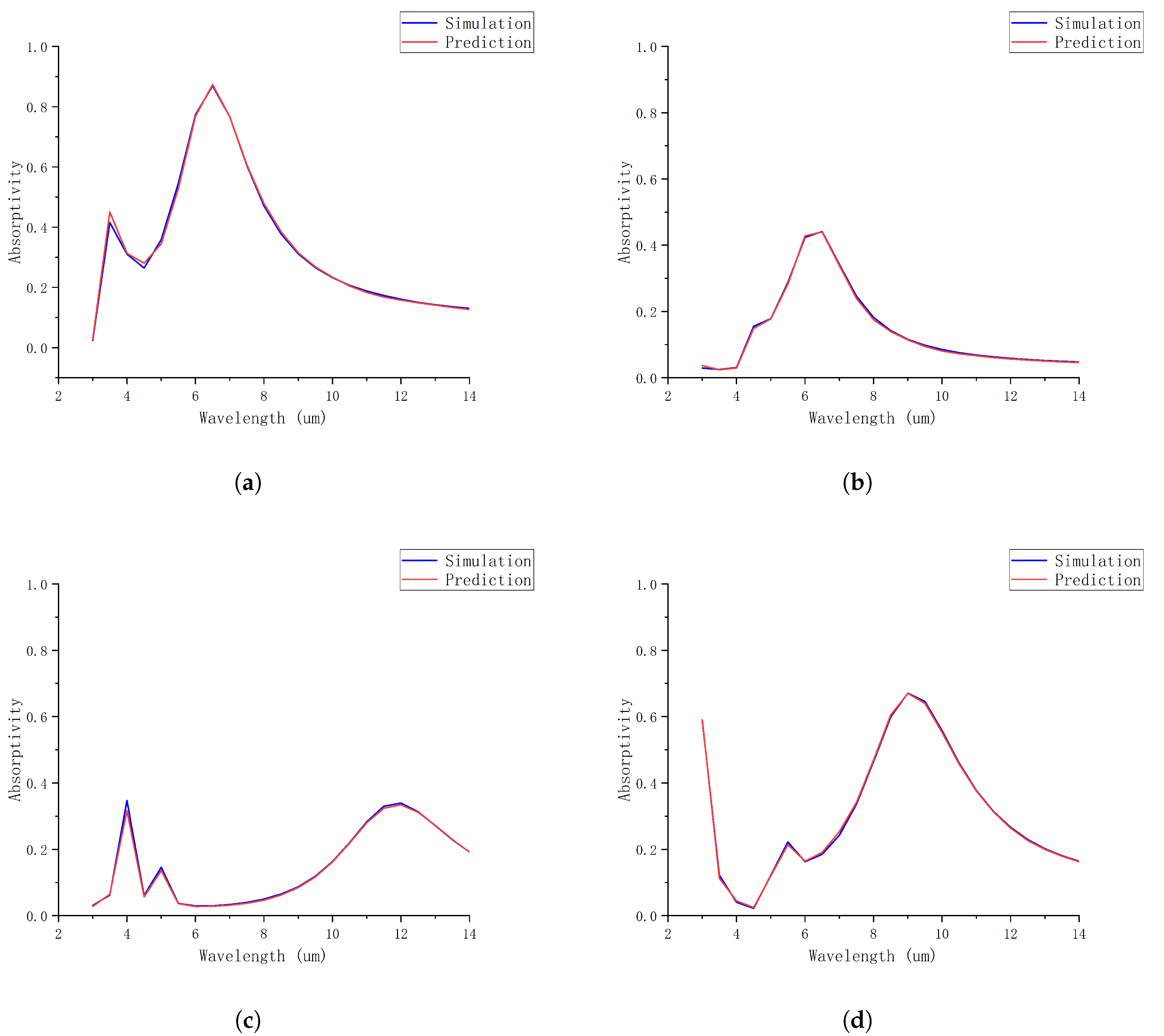
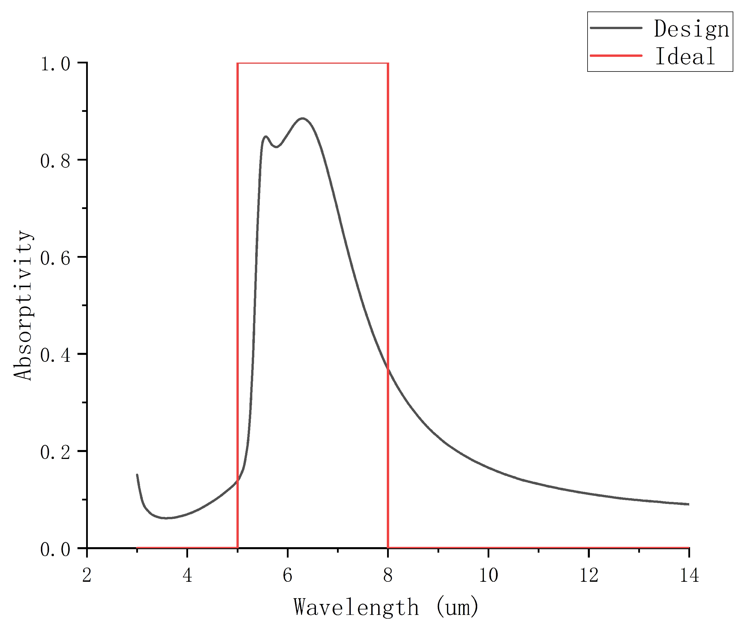
3. Result
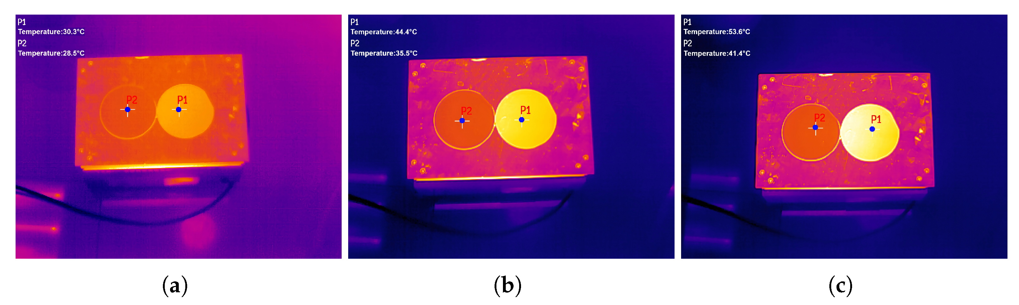
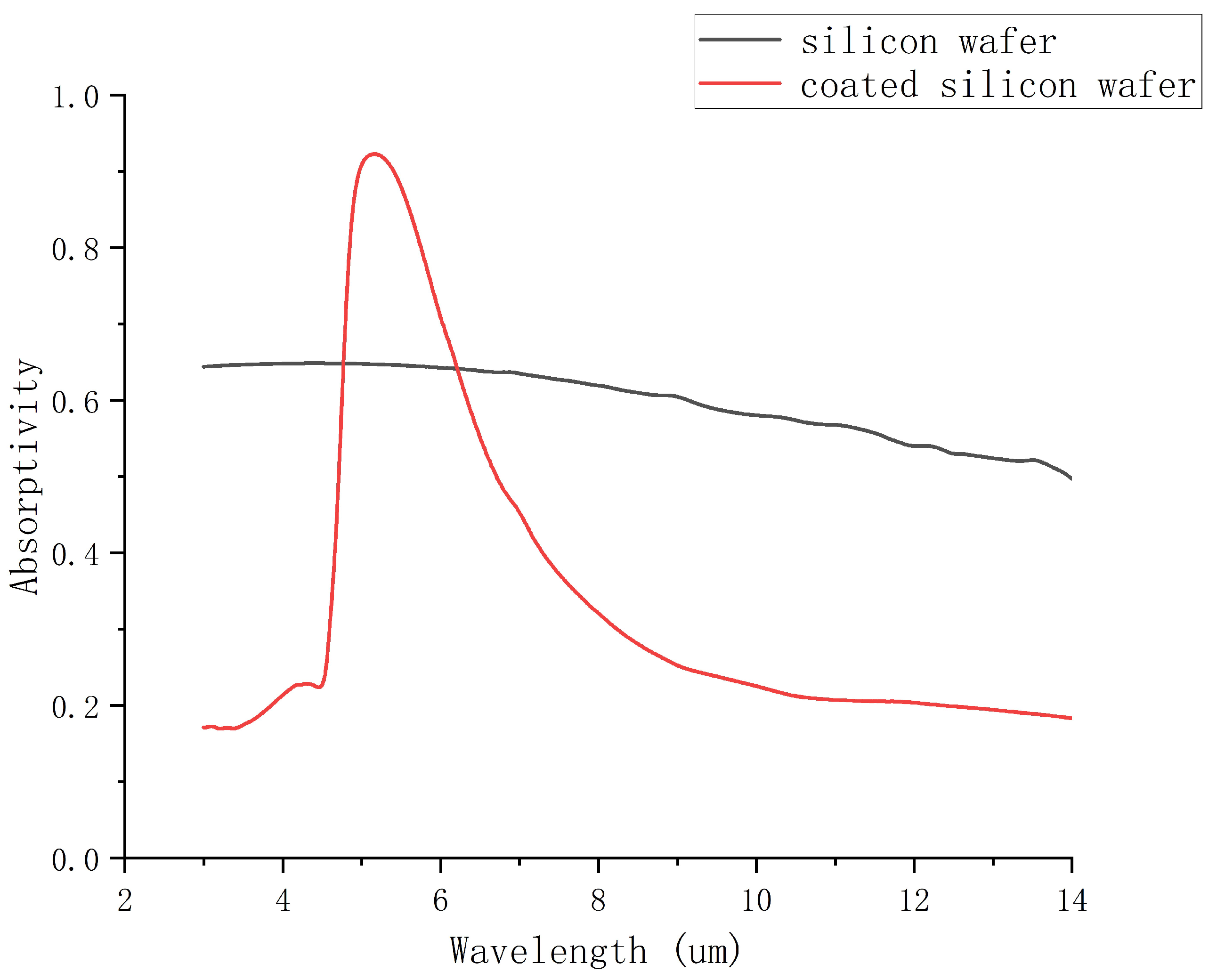
4. Experiment
5. Discussion
6. Conclusions
Author Contributions
Funding
Data Availability Statement
Conflicts of Interest
References
- Yang, J.; Zhang, X.; Zhang, X.; Wang, L.; Feng, W.; Li, Q. Beyond the visible: Bioinspired infrared adaptive materials. Adv. Mater. 2021, 33, 2004754. [Google Scholar] [CrossRef] [PubMed]
- Li, Y.; Li, W.; Han, T.; Zheng, X.; Li, J.; Li, B.; Fan, S.; Qiu, C.W. Transforming heat transfer with thermal metamaterials and devices. Nat. Rev. Mater. 2021, 6, 488–507. [Google Scholar] [CrossRef]
- Raman, A.P.; Anoma, M.A.; Zhu, L.; Rephaeli, E.; Fan, S. Passive radiative cooling below ambient air temperature under direct sunlight. Nature 2014, 515, 540–544. [Google Scholar] [CrossRef]
- Bhatia, B.; Leroy, A.; Shen, Y.; Zhao, L.; Gianello, M.; Li, D.; Gu, T.; Hu, J.; Soljačić, M.; Wang, E.N. Passive directional sub-ambient daytime radiative cooling. Nat. Commun. 2018, 9, 5001. [Google Scholar] [CrossRef]
- Zhang, W.; Xu, G.; Zhang, J.; Wang, H.; Hou, H. Infrared spectrally selective low emissivity from Ge/ZnS one-dimensional heterostructure photonic crystal. Opt. Mater. 2014, 37, 343–346. [Google Scholar] [CrossRef]
- Zhu, H.; Li, Q.; Zheng, C.; Hong, Y.; Xu, Z.; Wang, H.; Shen, W.; Kaur, S.; Ghosh, P.; Qiu, M. High-temperature infrared camouflage with efficient thermal management. Light. Sci. Appl. 2020, 9, 60. [Google Scholar] [CrossRef]
- Hu, R.; Xi, W.; Liu, Y.; Tang, K.; Song, J.; Luo, X.; Wu, J.; Qiu, C.W. Thermal camouflaging metamaterials. Mater. Today 2021, 45, 120–141. [Google Scholar] [CrossRef]
- Zouhdi, S.; Sihvola, A.; Vinogradov, A.P. Metamaterials and Plasmonics: Fundamentals, Modelling, Applications; Springer Science & Business Media: Berlin/Heidelberg, Germany, 2008. [Google Scholar] [CrossRef]
- Maier, S.A. Plasmonics: Fundamentals and Applications; Springer: Berlin/Heidelberg, Germany, 2007; Volume 1. [Google Scholar] [CrossRef]
- Zayats, A.V.; Maier, S. Active Plasmonics and Tuneable Plasmonic Metamaterials; John Wiley & Sons: Hoboken, NJ, USA, 2013. [Google Scholar] [CrossRef]
- Jiang, X.; Zhang, Z.; Ma, H.; Du, T.; Luo, M.; Liu, D.; Yang, J. Tunable mid-infrared selective emitter based on inverse design metasurface for infrared stealth with thermal management. Opt. Express 2022, 30, 18250–18263. [Google Scholar] [CrossRef] [PubMed]
- Du, K.K.; Li, Q.; Lyu, Y.B.; Ding, J.C.; Lu, Y.; Cheng, Z.Y.; Qiu, M. Control over emissivity of zero-static-power thermal emitters based on phase-changing material GST. Light. Sci. Appl. 2017, 6, e16194. [Google Scholar] [CrossRef] [PubMed]
- Zhang, J.K.; Shi, J.M.; Zhao, D.P.; Wang, Q.C.; Wang, C.M. Realization of compatible stealth material for infrared, laser and radar based on one-dimensional doping-structure photonic crystals. Infrared Phys. Technol. 2017, 85, 62–65. [Google Scholar] [CrossRef]
- Liu, M.; Xia, S.; Wan, W.; Qin, J.; Li, H.; Zhao, C.; Bi, L.; Qiu, C.W. Broadband mid-infrared non-reciprocal absorption using magnetized gradient epsilon-near-zero thin films. Nat. Mater. 2023, 22, 1196–1202. [Google Scholar] [CrossRef]
- Peng, L.; Liu, D.; Cheng, H.; Zhou, S.; Zu, M. A multilayer film based selective thermal emitter for infrared stealth technology. Adv. Opt. Mater. 2018, 6, 1801006. [Google Scholar] [CrossRef]
- Zhu, H.; Li, Q.; Tao, C.; Hong, Y.; Xu, Z.; Shen, W.; Kaur, S.; Ghosh, P.; Qiu, M. Multispectral camouflage for infrared, visible, lasers and microwave with radiative cooling. Nat. Commun. 2021, 12, 1805. [Google Scholar] [CrossRef] [PubMed]
- Molesky, S.; Lin, Z.; Piggott, A.Y.; Jin, W.; Vucković, J.; Rodriguez, A.W. Inverse design in nanophotonics. Nat. Photonics 2018, 12, 659–670. [Google Scholar] [CrossRef]
- Liu, C.; Maier, S.A.; Li, G. Genetic-algorithm-aided meta-atom multiplication for improved absorption and coloration in nanophotonics. ACS Photonics 2020, 7, 1716–1722. [Google Scholar] [CrossRef]
- Martin, S.; Rivory, J.; Schoenauer, M. Synthesis of optical multilayer systems using genetic algorithms. Appl. Opt. 1995, 34, 2247–2254. [Google Scholar] [CrossRef] [PubMed]
- Ma, D.; Li, Z.; Liu, W.; Geng, G.; Cheng, H.; Li, J.; Tian, J.; Chen, S. Deep-learning enabled multicolor meta-holography. Adv. Opt. Mater. 2022, 10, 2102628. [Google Scholar] [CrossRef]
- Bertsimas, D.; Tsitsiklis, J. Simulated annealing. Stat. Sci. 1993, 8, 10–15. [Google Scholar] [CrossRef]
- Forestiere, C.; Donelli, M.; Walsh, G.F.; Zeni, E.; Miano, G.; Dal Negro, L. Particle-swarm optimization of broadband nanoplasmonic arrays. Opt. Lett. 2010, 35, 133–135. [Google Scholar] [CrossRef]
- Yang, C.; Hong, L.; Shen, W.; Zhang, Y.; Liu, X.; Zhen, H. Design of reflective color filters with high angular tolerance by particle swarm optimization method. Opt. Express 2013, 21, 9315–9323. [Google Scholar] [CrossRef] [PubMed]
- Christiansen, R.E.; Sigmund, O. Inverse design in photonics by topology optimization: Tutorial. J. Opt. Soc. Am. B 2021, 38, 496–509. [Google Scholar] [CrossRef]
- Peurifoy, J.; Shen, Y.; Jing, L.; Yang, Y.; Cano-Renteria, F.; DeLacy, B.G.; Joannopoulos, J.D.; Tegmark, M.; Soljačić, M. Nanophotonic particle simulation and inverse design using artificial neural networks. Sci. Adv. 2018, 4, eaar4206. [Google Scholar] [CrossRef]
- Liu, Z.; Zhu, D.; Rodrigues, S.P.; Lee, K.T.; Cai, W. Generative model for the inverse design of metasurfaces. Nano Lett. 2018, 18, 6570–6576. [Google Scholar] [CrossRef] [PubMed]
- Liu, D.; Tan, Y.; Khoram, E.; Yu, Z. Training deep neural networks for the inverse design of nanophotonic structures. ACS Photonics 2018, 5, 1365–1369. [Google Scholar] [CrossRef]
- Guan, Q.; Raza, A.; Mao, S.S.; Vega, L.F.; Zhang, T. Machine learning-enabled inverse design of radiative cooling film with on-demand transmissive color. ACS Photonics 2023, 10, 715–726. [Google Scholar] [CrossRef]
- Wang, L.; Dong, J.; Zhang, W.; Zheng, C.; Liu, L. Deep learning assisted optimization of metasurface for multi-band compatible infrared stealth and radiative thermal management. Nanomaterials 2023, 13, 1030. [Google Scholar] [CrossRef] [PubMed]
- Jiang, A.; Osamu, Y.; Chen, L. Multilayer optical thin film design with deep Q learning. Sci. Rep. 2020, 10, 12780. [Google Scholar] [CrossRef] [PubMed]
- Liao, X.; Gui, L.; Gao, A.; Yu, Z.; Xu, K. Intelligent design of the chiral metasurfaces for flexible targets: Combining a deep neural network with a policy proximal optimization algorithm. Opt. Express 2022, 30, 39582–39596. [Google Scholar] [CrossRef] [PubMed]
- Yu, S.; Zhou, P.; Xi, W.; Chen, Z.; Deng, Y.; Luo, X.; Li, W.; Shiomi, J.; Hu, R. General deep learning framework for emissivity engineering. Light. Sci. Appl. 2023, 12, 291. [Google Scholar] [CrossRef] [PubMed]
- Glorot, X.; Bordes, A.; Bengio, Y. Deep sparse rectifier neural networks. In Proceedings of the Fourteenth International Conference on Artificial Intelligence and Statistics, Fort Lauderdale, FL, USA, 11–13 April 2011; pp. 315–323. [Google Scholar]
- Yu, D.; Wang, X.; Ma, Y.; Chen, M.; Shen, J.; Li, Y.; Wu, X. Dual-dielectric Fabry-Perot film for visible-infrared compatible stealth and radiative heat dissipation. Opt. Commun. 2025, 574, 131173. [Google Scholar] [CrossRef]


| Method | Performance | Flexible Target | Needs Extra Data |
|---|---|---|---|
| MLP + DQN | 0.80955 | Yes | No |
| MLP + GA | 0.79763 | No | No |
| TNN | 0.77638 | Yes | Yes |
Disclaimer/Publisher’s Note: The statements, opinions and data contained in all publications are solely those of the individual author(s) and contributor(s) and not of MDPI and/or the editor(s). MDPI and/or the editor(s) disclaim responsibility for any injury to people or property resulting from any ideas, methods, instructions or products referred to in the content. |
© 2025 by the authors. Licensee MDPI, Basel, Switzerland. This article is an open access article distributed under the terms and conditions of the Creative Commons Attribution (CC BY) license (https://creativecommons.org/licenses/by/4.0/).
Share and Cite
Zhang, K.; Liu, D.; Yang, S. Design Method of Infrared Stealth Film Based on Deep Reinforcement Learning. Photonics 2025, 12, 67. https://doi.org/10.3390/photonics12010067
Zhang K, Liu D, Yang S. Design Method of Infrared Stealth Film Based on Deep Reinforcement Learning. Photonics. 2025; 12(1):67. https://doi.org/10.3390/photonics12010067
Chicago/Turabian StyleZhang, Kunyuan, Delian Liu, and Shuo Yang. 2025. "Design Method of Infrared Stealth Film Based on Deep Reinforcement Learning" Photonics 12, no. 1: 67. https://doi.org/10.3390/photonics12010067
APA StyleZhang, K., Liu, D., & Yang, S. (2025). Design Method of Infrared Stealth Film Based on Deep Reinforcement Learning. Photonics, 12(1), 67. https://doi.org/10.3390/photonics12010067