Abstract
The evaluation of the focal field of Cassegrain antennas is crucial for the design and optimization of the complex feeds in quasi-optical systems. However, employing traditional physical optics methods generates high computational complexity and is inefficient. An accurate and efficient calculation method of Cassegrain antennas’ focal fields that involves a range of incidence angles is proposed, which integrates ray tracing and vector diffraction integration (RT-VDI) theories. It can calculate the focal field in any given or predefined incident direction, not limited to the case of axial incidence. In addition, the use of the equivalent parabolic theory greatly simplifies the process of integral calculation. Moreover, ray tracing and integration operations are executed upon the calculation of the reflector to further improve efficiency. Numerical examples are presented to demonstrate the accuracy and efficiency of the proposed method.
1. Introduction
Reflector antennas are utilized in a lot of applications that require a high-gain antenna system, including wireless communication, radar, unmanned aerial vehicles, intelligent transportation, and other quasi-optical systems [1,2]. Due to its compact structure and convenience in terms of design and fabrication, the Cassegrain antenna is consistently identified as the fundamental multiple beam antenna scheme [3]. The focal plane field is the electromagnetic wave distribution near the focus of reflector antennas. The analysis of the focal plane field is essential for the design of Cassegrain antennas, and especially for the design of their feed array [4,5]. Based on the analysis of the focal field, the position of the feed source and the required field distribution can be accurately obtained. These can help overcome some design challenges in intricate microwave optical systems like shaped beam antennas and beam waveguide antennas. Therefore, the analysis of the focal plane field can guide the design and optimization of the feed source and improve the overall performance of the system [6,7].
There are two main types of calculation methods for focal fields: full-wave numerical calculation methods and high-frequency approximation methods. Full-wave numerical methods such as the Finite Element Method (FEM), Finite difference time domain (FDTD), Moment Methods (MOM), etc., require a huge amount of computing resources and a long calculation time, which are not suitable for the analysis and calculation of a parabolic focal plane field [8,9]. Although the computational accuracy of high-frequency approximation algorithms is not as high as that of the full-wave methods, they have the characteristics of a small computational memory and high computational efficiency [10]. Therefore, high-frequency approximation algorithms are widely used in the calculation of electrically large targets and the design and optimization of antennas [11,12]. Typical high-frequency approximation algorithms include physical optics (PO), geometric optics (GO), shooting and bouncing rays (SBRs) and other variant methods like them [13,14]. WANG et al. analyzed the focal field of a biased parabolic antenna for a plane wave incidented in the axial direction by induced-current-method-based PO [15]. Naeini analyzed the scalar pulse response field above the focal plane under paraxial incidence [16]. However, they only considered paraxial incidence and ignored the changes in the focal field that happen when off-axis incidence occurs, which is crucial for multi-beam antenna design [17]. C. Letrou proposed a multilevel physical optics (MLPO) algorithm for calculating the parabolic focal field for a range of incidence angles, which reduces the computational complexity of the parabolic focal field [18]. However, the aforementioned study mainly focused on single reflector antennas and did not further explore the calculation problem of the focal field of Cassegrain antennas. Currently, the analysis of the focal field of Cassegrain antennas is mostly based on the PO method. Due to the necessity of computing numerous integrals, it encounters challenges in terms of computational complexity and inefficiencies.
To solve the problem, an accurate and efficient calculation method for the focal fields of Cassegrain antennas based on ray tracing and vector diffraction integration (RT-VDI) is proposed. Moreover, this method simplifies the integral calculation by introducing equivalent parabolic theory. Several examples prove that our method is more efficient than the traditional induced current method (ICM).
2. Traditional Induced Current Method
Figure 1 shows classical Cassegrain geometry. This setup consists of a paraboloidal main reflector and a small hyperboloidal subreflector. The origin of the Cartesian coordinate system is located at the vertex of the parabolic surface. F and are the two focal points of the hyperbolic surface, respectively. The plane centered on F is the focal plane.
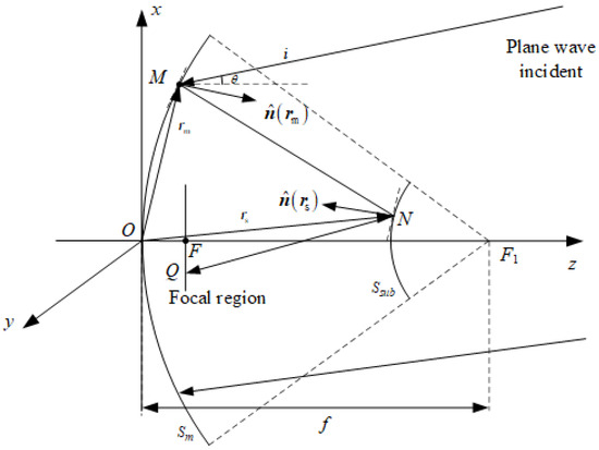
Figure 1.
Cassegrain antenna.
In this section, the fields in the focal region (at ) are calculated by means of the induced current method. Firstly, we assume that the source position is located in the far-field region. Therefore, the electromagnetic waves incident on the main surface can be regarded as plane waves. The incident electric field can be expressed as [19]
where is the position vector of any point M on the main reflection surface. is the polarization direction of the far-field plane waves, which we here set to the x direction; represents the electric field intensity; k is the wavenumber, and ; is the position vector of any point N on the hyperboloidal subreflector surface; and is the unit vector of the incident plane wave, as shown in the figure. This field induces a current on the main reflector surface as follows:
where is the normal vector at any point M position on the main reflection surface.
Therefore, the magnetic field distribution on the secondary reflection surface can be obtained as follows:
where is the “illuminated area” on the main reflection surface. Green’s function can be approximated as follows in the near field [19]:
where ; are the observation and source point, respectively.
Next, due to the distribution of the incident magnetic field , the equivalent current distribution on the secondary reflection surface can be obtained:
where represents the outward unit normal on the surface of the hyperboloidal subreflector.
Finally, based on the method of the analysis of the induced current of the reflector antenna, the electric field distribution at any point Q on the focal plane field can be obtained [20].
where ; is the “illuminated area” on the subreflector surface and ; and are the observation and source point, respectively.
The traditional induced current method is based on the principle of physical optics. It performs two area division operations between the primary and secondary reflection surfaces in order to solve the problem of calculating the focal field of Cassegrain antennas, which brings great difficulties to the computer’s numerical calculations. Therefore, it is crucial to study an efficient method for calculating the focal field of Cassegrain antennas.
3. Proposed Method
This section proposes an efficient calculation method for the focal field of Cassegrain antennas based on ray tracing and vector diffraction integration.
Figure 2 shows the distribution of the focal plane field when the incident angle is 0°, 2°, 4°, or 6° at different f/D.

Figure 2.
Comparison of the −3 dB and −10 dB distribution of the focal plane field with different f/D. (a) f/D = 0.3. (b) f/D = 0.5. (c) f/D = 1.0.
This figure shows that the distortions will be more and more inconspicuous as the f/D increases. Moreover, in parabolic antenna systems, obvious distortions in the focal plane field will not appear with different incident angles when f/D is greater than 1.0. Therefore, we can focus on the mainlobe of the focus area in the focal plane of large f/D systems. In double reflector systems, the equivalent f/D is usually greater than 1.0. Therefore, it will not affect our analysis of the distribution of the focal plane field.
In the proposed method, firstly, based on the principle of parabolic equivalence, the Cassegrain antenna is the equivalent of a long-focal-length single-reflector antenna. Then, the field distribution in the focal region is derived using ray tracing and vector diffraction integration methods.
Figure 3 shows a Cassegrain antenna and its equivalent parabola.
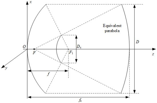
Figure 3.
A Cassegrain antenna and its equivalent parabola.
According to the equivalent parabolic theory, a dual-reflector antenna is equivalent to a single parabolic antenna with a long focal length. Its equivalent focal length is
where f is the focal length of the paraboloidal main reflector. M is the amplification factor,
where e is the eccentricity of the hyperbolic reflector.
A geometric schematic diagram of the equivalent single-reflector antenna is shown in Figure 4.
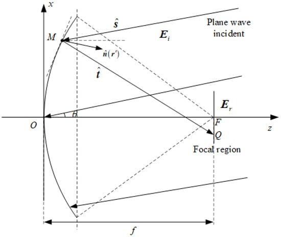
Figure 4.
Equivalent single-reflector antenna.
Firstly, using the ray tracing method, the reflection field of the parabolic antenna is derived from the distribution of incident waves .
According to the law of reflection in geometric optics,
where is the unit outward normal vector at the surface point.
According to the law of reflection, the reflection unit vector of the incident vector after being reflected by a parabolic surface is
Therefore, the corresponding magnetic field vector can be calculated:
Next, the field strength distribution on the focal plane can be solved using the vector diffraction integration method based on the above distribution.
The Stratton–Chu formula is an aperture diffraction integral formula derived from the Maxwell equation and Green’s formula, which can be used to solve the scattering field distribution on the focal plane via the vector field on the parabolic surface. According to the Stratton–Chu formula, the field strength at the field point Q in the focal plane is
where ; and are the observation and source point, from subreflector to the focal plane.
We can decompose the above equation into
where and represent the distribution of the current and magnetic flux, respectively,
4. Results
In this section, several examples were designed to demonstrate the accuracy and efficiency of our RT-VDI method. All the calculations results below were calculated on a PC with i9-13900HX 2.20 GHz CPUs and 16.0 GB of memory.
4.1. Accuracy
To study the accuracy of the proposed method, we calculated the focal field distribution under axial incidence. In addition, we analyzed the mainlobe region of the focused beam that we are concerned with at different incident angles. In this study, we have used the classical Cassegrain reflector, and the following values were selected: , , , and . Figure 5 shows the focal field distribution calculated by the proposed RT-VDI method and FEKO 2022.3.0 [21]. The range of the focal plane is 60 ∗ 60 mm in the case where the radiation on the mirror is incident parallel to the axis of the Cassegrain antennas.
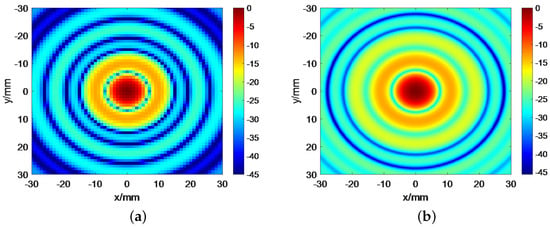
Figure 5.
Comparison of the distribution of the focal plane field at different axial incidences. (a) The result of the RT-VDI method. (b) The result of FEKO 2022.3.0.
The focal field distribution along the x-axis at different incident angles is compared with that of the ICM and FEKO 2022.3.0, as shown in Figure 6.
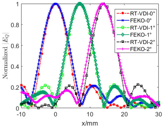
Figure 6.
Plot for along the x-axis with different calculations. The incident angle is 0°, 1°, or 2°, respectively.
By comparing the focal field results shown in Figure 5 and Figure 6, it can be seen that the results in the mainlobe region that we interested in obtained by the RT-VDI method agree well with those of the traditional ICM and FEKO 2022.3.0.
Figure 7 shows the distance at which the central point of the focus beam deviates from the focus at different incident angles.
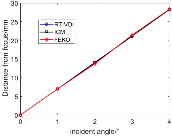
Figure 7.
The distance from the focus of different incident angles.
According to the results, the statistical average error between the RT-VDI method and the traditional method is nearly 0.02 mm, which is much lower than the distance from the focus. The results obtained by these two methods are almost the same, and both are consistent with the FEKO 2022.3.0 results.
To further illustrate the accuracy of the proposed RT-VDI method, the beamwidth of the mainlobe of the focused region at different incident angles is shown in Figure 8. According to the results, the beamwidth errors of the −3 dB, −5 dB, and −7 dB RT-VDI method and traditional ICM are 0.3 mm, 0.4 mm, and 0.5 mm, respectively. Compared with the corresponding beamwidth, these errors are nearly 4.5%, 5.0%, and 5.3%, respectively. Therefore, the results obtained by the ICM and the proposed RT-VDI method are in good agreement. Moreover, it has been proven that our method has a good calculation accuracy compared to the results of the FEKO 2022.3.0.
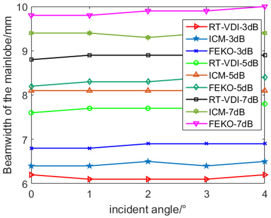
Figure 8.
Beamwidth of the mainlobe at different incident angles.
4.2. Efficiency
We first analyzed the computational complexity of the traditional methods and the proposed method. Firstly, in order to reduce computational complexity, we can assume that the number of points to be evaluated on both the secondary reflection surface and the focal plane is approximately calculated points.
In Equations (3) and (6), we assume that the numerical calculation of this integral requires summing up the terms, each of which involves calculating the integrand function at the intersection point. The complete feature description of the antenna requires analyzing the receiving mode in the direction that covers the sector of interest, as well as the frequency spanning the relevant bandwidth. Therefore, directly evaluating the antenna’s focal field would result in an astonishing computational complexity of . This complexity makes direct methods impractical, especially when design optimization requires repeated calculations. In contrast, in the proposed computational method, the radiation calculation of the subreflector is omitted. The proposed method reduces the asymptotic complexity to roughly . Compared with the traditional induced current method, this result emphasizes the computational savings produced by the proposed RT-VDI method.
In order to demonstrate the effectiveness of this method more clearly, we investigated the efficiency of the proposed approach with respect to the observation region’s size. The observation region is . The size of the observation plane is varied by setting the observation number = 1 , 4, and 2.5. The calculation times of the two solutions are listed in Table 1.

Table 1.
Computation time with different sizes of observation region.
According to these results, the efficiency of the proposed method is superior to the traditional method. Meanwhile, the speedup ratio is improved with the increase in computational amount. This validates the analysis in Section 3, which suggests that the proposed method would be very attractive for cases where scattering fields corresponding to multiple incident waves have to be evaluated individually.
5. Conclusions
To solve the difficulties with the traditional induced current method in the focal field scattering computation of Cassegrain antennas, an accurate and efficient method based on ray tracing and vector diffraction integration theory is proposed. As the method directly utilizes the equivalent paraboloid method, it greatly simplifies the process of the integration operations. In addition, this method is applicable to cases of plane waves incident in any direction. Hence, the proposed method is attractive for multi-beam antenna applications. Numerical experiments with relatively complex configurations have shown that its accuracy is basically consistent with traditional methods, while it leads to a significant improvement in computational efficiency.
Author Contributions
Conceptualization, H.L. and Y.J.; methodology, H.L.; software, D.L.; validation, H.L., H.X., and H.F.; formal analysis, H.F.; investigation, H.X.; resources, H.F.; data curation, H.L.; writing—original draft preparation, H.L.; writing—review and editing, Y.J.; visualization, D.L.; supervision, H.X.; project administration, H.F.; funding acquisition, Y.J. All authors have read and agreed to the published version of the manuscript.
Funding
This research was funded by the National Key Research and Development Program of China under Grant 2022YFB3902400.
Institutional Review Board Statement
Not applicable.
Informed Consent Statement
Not applicable.
Data Availability Statement
Data available on request from the authors.
Conflicts of Interest
The authors declare no conflicts of interest.
References
- Balasubramanian, M.; Campbell, S.D.; Werner, D.H.; Hand, T.H. A Shaped Reflector Antenna Design Approach for Contoured Beam Synthesis With Surface Curvature Constraints. IEEE Trans. Antennas Propag. 2024, 72, 1297–1307. [Google Scholar] [CrossRef]
- van den Biggelaar, A.; Al-Rawi, A.; Johannsen, U.; Smolders, A. 64 Element Active Phased Array as Focal Plane Array Feed for Reflector Antennas for mm-Wave Wireless Communications. In Proceedings of the 2020 14th European Conference on Antennas and Propagation (EuCAP), Copenhagen, Denmark, 15–20 March 2020; pp. 1–5. [Google Scholar] [CrossRef]
- Wang, J.; Ge, J.; Zhou, Y.; Xia, H.; Yang, X. Design of a High-Isolation 35/94-GHz Dual-Frequency Orthogonal-Polarization Cassegrain Antenna. IEEE Antennas Wirel. Propag. Lett. 2017, 16, 1297–1300. [Google Scholar] [CrossRef]
- Shi, Q.; Du, B.; Tian, J.; Niu, S.; Wu, Y. Design of a Ka Band Phased Array Feed Based on the Focal Plane Field Sampling for Edge Beam. In Proceedings of the 2023 Cross Strait Radio Science and Wireless Technology Conference (CSRSWTC), Guilin, China, 10–13 November 2023; pp. 1–3. [Google Scholar] [CrossRef]
- Chen, Q.; Fan, Y. Design of Focal Plane Array with Lens for W-band Short Range Passive Imaging. In Proceedings of the 2019 IEEE Asia-Pacific Microwave Conference (APMC), Singapore, 10–13 December 2019; pp. 859–861. [Google Scholar] [CrossRef]
- Gunaratne, T.K.; Bruton, L.; Agathoklis, P. Broadband Beamforming of Focal Plane Array (FPA) Signals Using Real-Time Spatio-Temporal 3D FIR Frustum Digital Filters. IEEE Trans. Antennas Propag. 2011, 59, 2029–2040. [Google Scholar] [CrossRef]
- Pakkathillam, J.K.; Sivaprakasam, B.T.; Poojali, J.; Krishnamurthy, C.V.; Arunachalam, K. Tailoring Antenna Focal Plane Characteristics for a Compact Free-Space Microwave Complex Dielectric Permittivity Measurement Setup. IEEE Trans. Instrum. Meas. 2021, 70, 6000412. [Google Scholar] [CrossRef]
- Wu, Y.; Liang, W.; Ma, C.; Wang, M.; Zheng, H.; Li, E. Thin Absorber with Dispersive Medium Simulated by Conformal Hybrid Explicit Implicit FDTD Method. IEEE Antennas Wirel. Propag. Lett. 2024, 23, 2461–2465. [Google Scholar] [CrossRef]
- Wang, Y.Y.; Zhan, Q.; Feng, H.; Wang, Y.D.; Sun, B.; Yin, W.Y. A Novel Matrix-Free Finite Element Method for Time-Harmonic Maxwell’s Equations. IEEE Trans. Antennas Propag. 2024, 72, 2609–2619. [Google Scholar] [CrossRef]
- Huo, J.; Xu, L.; Shi, X.; Yang, Z. An Accelerated Shooting and Bouncing Ray Method Based on GPU and Virtual Ray Tube for Fast RCS Prediction. IEEE Antennas Wirel. Propag. Lett. 2021, 20, 1839–1843. [Google Scholar] [CrossRef]
- Dong, C.L.; Guo, L.X.; Meng, X. An Accelerated Algorithm Based on GO-PO/PTD and CWMFSM for EM Scattering From the Ship Over a Sea Surface and SAR Image Formation. IEEE Trans. Antennas Propag. 2020, 68, 3934–3944. [Google Scholar] [CrossRef]
- Bian, Z.; Li, J.; Guo, L.; Luo, X. Analyzing the Electromagnetic Scattering Characteristics of a Hypersonic Vehicle Based on the Inhomogeneity Zonal Medium Model. IEEE Trans. Antennas Propag. 2021, 69, 971–982. [Google Scholar] [CrossRef]
- Ling, H.; Chou, R.C.; Lee, S.W. Shooting and bouncing rays: Calculating the RCS of an arbitrarily shaped cavity. IEEE Trans. Antennas Propag. 1989, 37, 194–205. [Google Scholar] [CrossRef]
- Li, J.; Li, K.; Guo, L.X.; Ren, Z.L. A Bi-Iterative Model for Electromagnetic Scattering From a PEC Object Partially Buried in Rough Sea Surface. IEEE Geosci. Remote Sens. Lett. 2018, 15, 493–497. [Google Scholar] [CrossRef]
- Wang, H.; Miao, J.; Jiang, J.; Wang, R. The focal region electric field distribution of an offset paraboloid. In Proceedings of the 2012 International Symposium on Communications and Information Technologies (ISCIT), Gold Coast, Australia, 2–5 October 2012; pp. 632–637. [Google Scholar] [CrossRef]
- Naeini, M.A.; Bruton, L.T. The 3D on-axis space-time scalar impulse response field of the parabolic reflector in the focal plane. In Proceedings of the 2011 IEEE Pacific Rim Conference on Communications, Computers and Signal Processing, Victoria, BC, Canada, 23–26 August 2011; pp. 394–398. [Google Scholar] [CrossRef]
- Budé, R.X.F.; Elsakka, A.; Johannsen, U.; Smolders, A.B. Wide-Scan Focal Plane Arrays for mmWave Point-to-Multipoint Communications. IEEE Open J. Antennas Propag. 2022, 3, 112–123. [Google Scholar] [CrossRef]
- Letrou, C.; Boag, A. An MLPO algorithm for fast evaluation of the focal plane fields of reflector antennas. In Proceedings of the 2012 6th European Conference on Antennas and Propagation (EUCAP), Prague, Czech Republic, 26–30 March 2012; pp. 3436–3437. [Google Scholar] [CrossRef]
- Chen, B.; Tong, C. Near-Field Scattering Prediction Based on Refined Time-Domain High-Frequency Method. IEEE Antennas Wirel. Propag. Lett. 2019, 18, 1194–1198. [Google Scholar] [CrossRef]
- Rahim, T.; Mughal, M.J.; Naqvi, Q.A.; Faryad, M. Focal Region Field of a Paraboloidal Reflector Coated with Isotropic Chiral Medium. Prog. Electromagn.-Res.-Pier 2009, 94, 351–366. [Google Scholar] [CrossRef][Green Version]
- TICRA Software. Available online: https://www.ticra.com/software/grasp/ (accessed on 11 July 2024).
Disclaimer/Publisher’s Note: The statements, opinions and data contained in all publications are solely those of the individual author(s) and contributor(s) and not of MDPI and/or the editor(s). MDPI and/or the editor(s) disclaim responsibility for any injury to people or property resulting from any ideas, methods, instructions or products referred to in the content. |
© 2024 by the authors. Licensee MDPI, Basel, Switzerland. This article is an open access article distributed under the terms and conditions of the Creative Commons Attribution (CC BY) license (https://creativecommons.org/licenses/by/4.0/).