Abstract
Based on the characteristics of plasmonic waveguides and resonators, we propose a refractive index (RI) sensor that couples a gear ring with a metal–insulator–metal (MIM) waveguide. Using the finite element method (FEM), we conduct extensive spectral analysis of the sensor’s properties in the near-infrared spectrum. Furthermore, we investigate the structural parameters affecting the refractive index sensing characteristics. This study reveals that the complexity of the ring cavity edge can significantly enhance the sensitivity of the nanosensor. Optimal structural performance parameters are selected when the number of gears is six, resulting in a sensitivity of 3102 nm/RIU and a Figure of Merit (FOM) of 57.4 for the sensing characteristics of the gear ring. It possesses the advantages of small size and high sensitivity. This nanoscale sensor design demonstrates high sensitivity in the field of industrial material temperature detection.
1. Introduction
Surface Plasmon Polaritons (SPPs) are electromagnetic waves that exist at the interface between a metal and dielectrics [1]. When light illuminates the interface, it interacts with the free electrons in the metal, giving rise to these electromagnetic waves. SPPs exhibit unique spectral characteristics, such as the ability to localize optical fields at the nanoscale, surpassing classical diffraction limits. Due to their ability to concentrate light in subwavelength structures, resulting in enhanced electric fields, SPPs are particularly suitable for nanoscale integration and find widespread applications in sensing, optical switches, and other fields [2,3]. They concentrate light within structures smaller than the wavelength of light. In these structures, light is confined to extremely small volumes, leading to a significant enhancement in the electric field. Field enhancement occurs when SPPs confine the light beam at the metal–dielectric interface at the nanoscale, resulting in the electromagnetic field intensity far exceeding the original electromagnetic field intensity of the incident light. This enhanced field is crucial for the performance of sensors, as it significantly improves the sensor’s responsiveness to target substances (such as biomolecules or chemicals) [4,5].
Moreover, the suitability of SPPs for nanoscale integration means that smaller, more precise sensors and optical components can be manufactured [6]. This capability is particularly advantageous for designing and fabricating systems with size constraints, achieving efficient light control and sensing in very small spaces [7,8]. For instance, in biosensors, SPPs can detect the presence of biomolecules, such as DNA hybridization or blood components. Thus, these properties of SPPs not only provide new tools for research but also give new possibilities for industrial and technological applications, especially in the field of precision measurement and high-sensitivity detection [9,10].
In optical devices, plasma sensors work when the refractive index of the filled media changes, allowing for the detection of even minor refractive index changes [11]. Therefore, enhancing the sensing behavior of plasma sensors requires adjusting the design parameters, optimizing structures, and using new materials. For example, silicon membrane primitive surfaces are a novel type of optical material structure capable of effectively controlling the propagation and scattering of incident light by designing micro- and nanoscale structures on the surface of a silicon membrane. When the surface of the silicon primitive membrane is exposed to optical signals, it can influence the intensity of the incident light. By monitoring this intensity change, variations in the refractive index of the surrounding medium can be inferred. The intensity detection technology based on silicon membrane primitive surfaces can also find applications in the field of communication. For example, it can be used to achieve modulation and demodulation of optical signals in photonic integrated circuits, as well as data transmission and processing in optical sensor networks [12,13].
The overall structure is Au-SiO2–graphene, which can be realized by tuning the Fermi energy level of graphene. The sensing performance of the absorber in an aqueous solution was simulated to discover the application of high refractive index sensitivity. The absorbers have an important role in high-sensitivity sensors, photothermal detection, and thermal radiation [14,15].
Metal–insulator–metal (MIM) waveguides are a variant of SPP waveguides, composed of two layers of metal sandwiching a layer of insulating material. They possess unique advantages, enabling the realization of complex optical structures in small dimensions with high integration. When light bends within the waveguide, it maintains high localization inside the waveguide, minimizing energy loss. MIM waveguides are also capable of deeply constraining light at subwavelength scales, thereby increasing the efficiency of light interaction with the medium [16,17,18].
Many studies have investigated the unique designs of RI sensors based on MIM waveguides. For instance, Butt explored a refractive index sensor based on a square ring-shaped MIM structure and utilized the finite element method (FEM) to model the transmission spectra and electric field distribution of the nanosensing structure. Their study achieved a sensitivity of 1200 nm/RIU and a FOM of 19.7 [19]. Zhu established an MIM waveguide with a U-shaped resonator, achieving a sensitivity of 825 nm/RIU and an FOM of 21.54. The superior sensing structure is capable of accurately identifying five types of pure edible vegetable oils at room temperature [20]. Rohimah designed an r-shaped resonator for a refractive index sensor in a MIM waveguide coupling system, achieving a sensitivity of 1333 nm/RIU [21]. Kazanskiy demonstrated a semi-ring resonator cavity by means of decorating nanodots with a sensitivity of 1084.21 nm/RIU [22].
Numerical results have been obtained by applying the designed sensing structure to different fields. For example, Sagor R H et al. designed a coupled cavity based on a metal–insulator–metal (MIM) waveguide combined with two unequal vertical rectangular cavities. This sensing was finally obtained with a maximum sensitivity of 2625.87 nm/RIU and a Figure of Merit (FOM) of 26.04. Human blood type was determined by utilizing the refractive index modeling of different human blood types including A, B, and O. In addition, as a temperature sensor, it had a sensing factor of −1.04 nm/°C [23].
Tavana S et al. proposed a metal–insulator–metal (MIM) structure consisting of a semicircular resonant cavity (SCRC) and a circular split ring resonator (SRR). Because of the interaction between the narrowband modes of the SRR and the broadband modes of the SCRC, this optical sensor could generate and support a double Fano resonance. Its maximum sensitivity and Figure of Merit (FOM) were 579 nm/RIU and 12.46, respectively [24]. Shen S et al. explored the transmission characteristics of a MIM waveguide structure based on a square ring resonator for SRS in a waveguide system. The optimization of the structure yielded a sensitivity of 6000 nm/RIU and a Figure of Merit (FOM) of 17 RIU−1. Also, it had a temperature sensing coefficient of −20.3 nm/°C [25].
However, the sensitivity of these RI sensors is generally limited, restricting their application scenarios. Therefore, this paper proposes a simple yet highly sensitive plasmonic sensor. Building upon the foundation of a ring-coupled cavity and a non-rectangular barrier, this paper further explores the impact of ring edge complexity on sensor sensitivity and the limiting capability of the rectangular barrier to light. When the measured substance is exposed to contact with the sensor, the refractive index changes, leading to alterations in the wavelength, intensity, or phase of the spectral curve. Finally, the RI sensor is composed of a gear ring coupled with a MIM waveguide. The complexity of the ring-shaped cavity edge contributes to enhancing sensor sensitivity, while the addition of the rectangular barrier aids in amplifying resonant SPP modes. With a typical sample sensitivity of 3102 nm/RIU and a FOM of 57.4, the device delivers excellent performance. This highly sensitive sensor design can detect variations in the refractive index of industrial material temperatures, obtaining propagation curves at different temperatures with minimal error.
2. Materials and Methods
The designed structure consists of a gear ring coupled to a MIM waveguide with a rectangular stub, as shown in Figure 1.
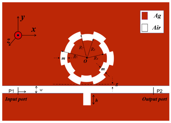
Figure 1.
Two-dimensional plan of the overall structure.
In the two-dimensional planar design of the model, the red and white areas represent silver and air, respectively. In the near-infrared region, silver has the minimum imaginary part of the relative dielectric constant. This implies that silver exhibits high sensitivity to light in this wavelength range, making it suitable for optical sensors (Table 1).

Table 1.
The parameters of the gear ring model.
This study uses a two-dimensional (2D) model to emulate the magnetic properties of a three-dimensional (3D) system [26,27]. On the one hand, this choice is motivated by the uniform nature of material properties, where the 3D effect has almost no influence on the magnetic domain profile. On the other hand, this method reduces the computational complexity, providing results that are nearly identical to those obtained in a real 3D scenario.
Simultaneously, the waveguide allows the SPP transmission by importing an isolating layer between the two metallic layers. The reason is that the odd symmetric modes are strongly coupled and attenuated in the insulating layer, leading to much greater energy loss and shorter transmission distances [28]. In contrast, the transmission distance of even-numbered symmetric modes is longer with less energy loss. This guarantees that there is only one even-symmetric transmission mode, and also effectively improves the transmission efficiency of even-symmetric mode and reduce energy losses. The dielectric layer thickness is chosen to be 50 nm, which can meet the requirements [29].
In Figure 1, the red area is the substrate with metallic silver material, which has a low loss of light; the white part stands for the air medium. The relative permittivity of the underlying silver material is defined [30]:
where is the infinite frequency relative dielectric constant, is the air relative dielectric constant, is the static dielectric constant, is the relaxation time, and is the conductivity.
The fundamental transverse magnetic mode of the MIM waveguide can be expressed as [31]:
where is the wave vector in the waveguide, is the width of the waveguide, , and . ( and are the diameters of the insulator, respectively).
In this article, the properties of the plasma sensor are measured by means of three different parameters as follows: FWHM denotes the sharpness of the spectral lines and FOM and sensitivity signify the index of component performance or sensing behavior. These three key parameters are essential. The formula is as follows [32]:
where and show the changes in the refractive index and wavelength, respectively. After confirming the required conditions, COMSOL Multiphysics 5.4a (COMSOL Inc., Stockholm, Sweden) is used to build a geometrical model of the plasma sensor. An ultra-fine triangular mesh section is chosen for the whole coupling structure. The reason is that ultra-fine triangular meshes can better capture the details of complex structures, especially for nanostructures or devices with tiny features. By increasing the density of the mesh, numerical errors can be reduced, making the simulation results more reliable and accurate. At the same time, ultra-fine meshes can capture the details of the structure more efficiently, reducing the need for large-scale computation.
Following the preliminary simulations, the wavelength range is chosen to be 1700–2800 nm in a 1 nm step. The initial parameters of the gear structure are given in the following table (Table 2).

Table 2.
Initial structural parameters.
3. Simulation Results and Analysis
In this section, we choose a gear ring with six gear edges for further analysis.
In Figure 2, a comprehensive representation is provided. The black line represents the transmission spectrum of a single waveguide with a rectangular barrier, depicted as a slightly upward-sloping line. This line signifies that most frequencies of light signals exhibit high transmittance, demonstrating a continuous broadband transmission characteristic.
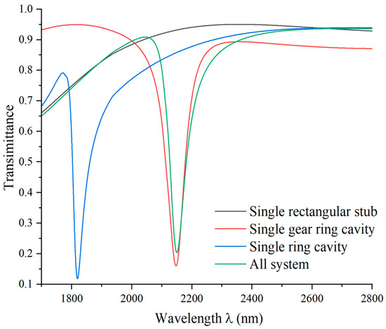
Figure 2.
Transmission spectra of the single rectangular stub (black line), single gear ring cavity (red line), single ring cavity (blue line), and the whole system (green line).
The red, blue, and green lines correspond to the single gear ring cavity, the single ring cavity with a smooth surface, and the gear ring cavity with six gear edges, respectively. These cavities all exhibit Fano resonance, which occurs when light passes through a cavity with a constant refractive index, leading to sharp peaks in the spectral graph within a very narrow wavelength range. To further investigate the implications of the cavity geometry parameters on the Fano resonance, we focus on the rectangular stub height and edges of the gear cavity complexity.
In Figure 3, it can be noticed that when the SPPs propagate through the waveguide and couple at the junction with the cavity, the resonance phenomenon is produced. In comparison, for the structure in Figure 3a, the magnetic field distribution associated with the waveguide is more concentrated within the cavity. The inclusion of a rectangular stub seems to restrict the propagation of SPPs in the waveguide, potentially making them more prone to coupling into the cavity. Thus, at specific wavelengths, the propagation of light in the structure is constrained, leading to enhanced resonance phenomena.
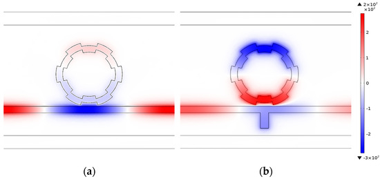
Figure 3.
(a) The magnetic field distribution of the single gear ring cavity at λ = 2150 nm. (b) The magnetic field distribution of the whole system at λ = 2150 nm.
In Figure 4, the complexity of the cavity edge does not impact the resonance phenomenon. However, the complexity of the gear ring cavity edge results in different ring-shaped magnetic field distributions for the two structures, which may lead to variations in light confinement capabilities. This difference ultimately results in distinct plasmonic sensing performances. As can be seen from the transmission curves shown by the blue and green lines in Figure 2, the complexity of the cavity edges improves the sensing performance, especially in terms of sensitivity.
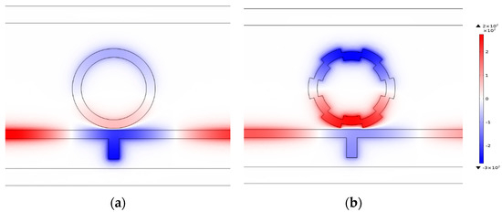
Figure 4.
(a) The magnetic field distribution of the ring cavity with a smooth surface at λ = 2150 nm. (b) The magnetic field distribution of the gear ring cavity with six gear edges at λ = 2150 nm.
According to the above analysis under different refractive indices, the sensing performance is initially analyzed when the number of gears is six and other parameters are fixed. In Figure 5a, various transmittance spectra are plotted for refractive indices ranging from 1.00 to 1.05. When the refractive index gradually increases, the appropriate wavelengths increase, leading to a redshift in the resonant wavelength. The waveform of the transmittance spectrum stays unaffected by changes in the refractive index, and they move equidistant, showing a certain stability. The RI sensor can be designed from this property. Figure 5b illustrates the linear relationship between the resonant wavelength and refractive index. Through linear fitting, the sensitivity of the gear ring nanosensor to the refractive index can reach 3102 nm/RIU with an FOM of 57.4.
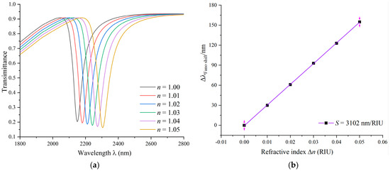
Figure 5.
(a) Transmission spectra of multiple refractive indices. (b) Fitted line for the variation in the refractive index.
Next, we analyze the complexity of the edges of the gear ring cavity.
The primary structural values remain fixed. We compare the transmission spectra for different numbers of gear edges and delve into the impact of gear ring edge complexity on the Fano resonance. The number of gear edges is set to 0, 2, 4, 6, 8, and 10. When the number of gear edges is 0, it presents a ring cavity with a smooth surface.
Figure 6a illustrates the transmittance spectra for different numbers of gear edges. As the number of gear edges increases, the wavelength also increases, leading to a redshift in the resonant wavelength. The difference between adjacent peaks increases, and when the number of gear edges is 10, an asymmetric transmission curve with a larger wavelength is observed, indicating a highly sensitive Fano resonance with a value of 3600 nm/RIU.
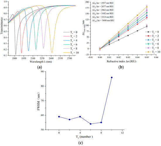
Figure 6.
(a) Transmission spectra of edge complexity of gear rings. (b) Fitting lines of sensitivity at different complexities at the edge of gear rings. (c) Variation in FWHM values for different complexities of gear rings.
However, as the number of gear edges increases, the FWHM of the obtained transmission curves widens. By calculation, we find a value of only 41.9. Although the sensitivity increases to some extent, the decrease in FOM suggests that the coupling cavity is more susceptible to environmental changes, resulting in a broader peak in the electromagnetic field and some loss of resolution.
Therefore, under the optimal geometric parameters of the cavity, namely, with six gear edges, we further investigate the size of the overall model.
Similarly, the initial values of other parameters remain invariant, the outer radius R1 is varied in steps of 5 nm from 210 nm to 230 nm, and the different circular radii of the ring are varied to guarantee that the structure is enlarged or reduced. The transmittance spectra for coupling cavities of different sizes are shown in Figure 7a, where the size of the gear ring increases with the radius, and the resonant wavelength exhibits a noticeable redshift.
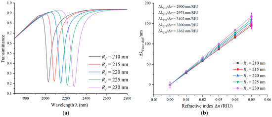
Figure 7.
(a) Transmission spectra of different sizes of gear rings. (b) Fitting lines of sensitivity for different sizes of gear rings.
Figure 7b depicts the sensitivity values for gear ring cavities of different sizes obtained using a mathematical linear method. The sensitivity goes from 2900 nm/RIU to 3362 nm/RIU as the increment in the size of the gear ring increases. We find that the control of the trough wavelength and the sensitivity can be enhanced by adapting the size of the overall structure. Therefore, in the design of optical devices, utilizing different sensitivities to choose the appropriate device size is feasible.
Subsequently, the influence of the rectangular stub height in a coupling structure is investigated. The height values are varied from 100 nm to 140 nm. As shown in Figure 8, the variation in the height of the barrier has no obvious effect on the angle position of the Fano resonance. When the rectangular barrier height becomes larger, the shape of the Fano resonance becomes more uneven, and the asymmetry becomes more pronounced. The introduction of the rectangular barrier, being a unique model, results in an asymmetric shape of the Fano resonance curve, which becomes more pronounced with increasing barrier height. This structure also induces a continuous broadband state that affects the line profile of the Fano resonance but does not change the wavelength at the dip position.
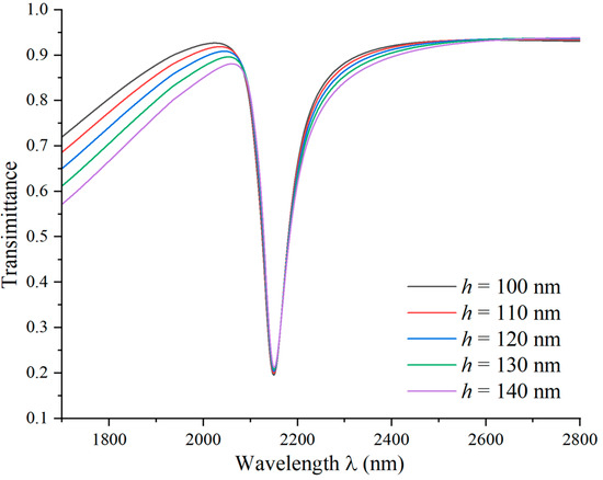
Figure 8.
Transmission spectra of rectangular stubs at different heights.
Finally, the influence of the coupling gap at the distance between the waveguide and the gear ring structure on the sensing performance is assessed. There is no change in the initial values, but the coupling gap g varies in the range of 10 nm to 30 nm in 5 nm steps. As shown in Figure 9a, by altering the amount of g, a blue shift in the spectral curve is observed, indicating a shift towards shorter wavelengths. In addition, the FWHM of the curve becomes diminished, and the transmittance increases. This suggests that the coupling becomes more challenging between SPP and the gear ring structure, and with an increase in the coupling gap, the electric field intensity gradually weakens.
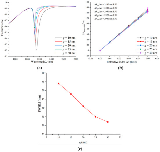
Figure 9.
(a) Transmission spectra of a range of coupling gaps. (b) Sensitivity-fitted lines with different coupling gaps. (c) Variation in FWHM values at the different coupling gaps.
The sensitivity fitting curve in Figure 9b shows a decrease in sensitivity from 3102 nm/RIU to 2900 nm/RIU as the coupling gap increases. So, the sensitivity can reach a maximum of 3102 nm/RIU when g = 10 nm is chosen. In a nutshell, the variation in the coupling gap has some effects on the optical properties, including a blue shift, changes in FWHM, and an increase in transmittance. However, within a certain range, changes in the coupling gap do not significantly alter the sensitivity of the sensor, suggesting that these variations may be negligible in sensor applications.
The preparation of nanoscale refractive index sensors typically involves precise nanomanufacturing techniques. For smaller-sized plasmonic sensors, advanced lithography and nanomanufacturing technologies may be necessary. The process begins with substrate preparation, where standard semiconductor processing techniques are employed to select a suitable substrate material, such as silicon, as the foundational layer for the sensor.
Subsequently, a layer of photoresist is coated onto the substrate. Typically, this is a photosensitive polymer that, through exposure and development, defines the desired pattern. Using a photolithography machine, the photoresist is exposed to project the desired sensor structure pattern onto it. For features smaller than 20 nanometers, high-resolution lithography techniques like electron beam or near-field lithography are often required.
After exposure, the developed photoresist removes material from unexposed areas, creating the desired pattern and essentially forming a template or mask. Following this, nanomanufacturing techniques such as electron beam etching (EBE) or ion beam etching (IBE) are utilized to etch the substrate based on the template, creating nanoscale structures.
Plasma deposition techniques are then employed to deposit the necessary sensing layer onto the nanostructures. This layer is typically made of materials like silver metal, which are suitable for measuring refractive index changes. Finally, the process concludes with necessary steps like cleaning, annealing, or other post-processing to ensure the performance and stability of the sensor.
In practical fabrication, the specific steps and techniques may vary depending on the sensor design and desired characteristics. It is crucial to note that nanoscale fabrication requires highly precise equipment and techniques.
The manufacturing process flow for the specific steps is shown in Figure 10.
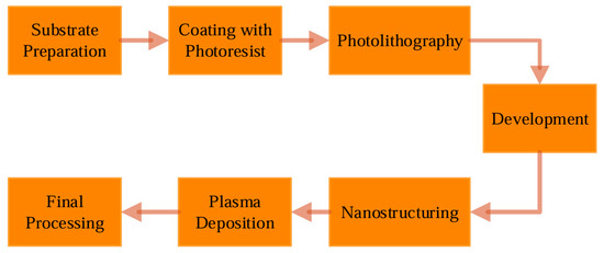
Figure 10.
Nanosensing manufacturing process flow steps.
Many studies have undertaken the design of this plasmonic sensor (Table 3).

Table 3.
Summary of the other literature sources.
4. Application
The sensing feature of the gear ring structure mentioned above brings the advantages of high sensitivity, easy miniaturization and integration, and it is also applicable to the temperature detection of industrial materials. Ethanol, being an excellent temperature-sensing medium, is picked to be the filling material. The melting point and boiling point of ethanol are −114.1 °C and 80 °C, respectively [33].
The refractive index temperature parameters of the different media in the sensing structure are 3.94 × 10⁻⁴ (°C−1) for ethanol, 9.30 × 10⁻⁶ (°C−1) for metallic silver, and 8.60 × 10⁻⁶ (°C−1) for a quartz substrate. Since the refractive index temperature sensing parameters of metallic silver and quartz are much smaller than that of an ethanol medium, they are negligible in the study of the effect of sensing characteristics.
When ethanol is used as a medium, the equation for the relationship between its refractive index and temperature is as follows [34]:
where and represent the temperature of industrial materials and room temperature, respectively. Room temperature is set at 20 °C.
The geometric parameters of the initial structure remain unchanged, with a gear ring consisting of six gears designed as the temperature sensing structure. The temperature detection range is set between −75 °C and 75 °C. After placing the nanosensor in ethanol, upon contact, air is expelled from the groove and replaced by the liquid. The refractive index of ethanol in the groove varies with temperature. The nanosensor measures the refractive index by monitoring light transmission or reflection, generating a Fano resonance curve. As the refractive index of ethanol changes with temperature, it influences the Fano resonance curve. The nanosensor detects and compares these changes with a predetermined temperature–refractive index relationship, thereby inferring the external temperature. Calibration against known temperatures ensures accurate measurements. The sensitivity relationship for temperature sensing is expressed as follows [29]:
where and represent the changes in wavelength and temperature, respectively. When the temperature increases in increments of 20 °C, ranging from −55 °C to 45 °C, the refractive indices are calculated as 1.38995, 1.38207, 1.37419, 1.36631, 1.36237, and 1.35015. The simulated transmission curves are shown in Figure 11a, where an increase in temperature leads to a blue shift in the spectral curve. Due to the excellent performance of modern optical instruments in precision measurement and wavelength accuracy, nanoscale wavelengths can be accurately detected. The trough in the transmission curve moves from 3540 nm to 3377 nm, indicating = 163 nm. Through linear fitting, the sensitivity is obtained, as shown in Figure 11b. The temperature sensor has a sensitivity of 1.664 nm/°C for good temperature sensing performance.
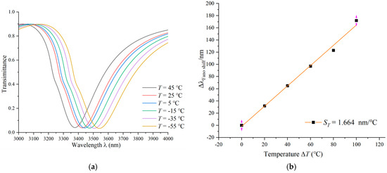
Figure 11.
(a) Transmission spectra at gradually increasing temperatures. (b) Sensitivity-fitted lines with different temperatures.
5. Conclusions
By utilizing the peculiar properties in optical Fano resonance, a highly precise nanoscale refractive index sensor has been successfully developed with a MIM waveguide and a gear ring. By analyzing the different geometric parameters of the sensing behavior, factors are considered, such as gear ring edge complexity, the inner and outer radii of the gear ring, and the gap at the distance between the gear ring and rectangular waveguide. Particularly, emphasis is given to the presentation of a rectangular stub and the influence of gear ring edge complexity on the sensing performance.
In addition, considering the complexity of the cavity edge, it is found to significantly enhance the sensitivity performance of the sensor. By comparing different numbers of gears, a gear ring with six gears is ultimately selected as the optimal configuration for the cavity.
In the end, upon optimizing the geometrical parameters, we managed to obtain a novel nanosensor. This gear ring cavity sensor exhibits outstanding performance, with a sensitivity of 3102 nm/RIU and an FOM of 57.4. The nanosensor not only performs well under industrial materials temperatures but also reliably monitors changes in temperature. The experimental data indicate that the refractive index temperature sensor has a sensitivity of 1.664 nm/°C, demonstrating excellent temperature sensing performance. This study provides strong support for the further application of nanoscale sensors.
Author Contributions
Conceptualization, S.Y. and L.L.; methodology, L.L.; software, Y.C.; validation, S.Y. and C.Z.; formal analysis, L.L. and Y.Z.; investigation, L.L.; resources, T.W. and Y.S.; data curation, L.L.; writing—original draft preparation, L.L.; writing—review and editing, Q.Z.; visualization, G.G. and Q.Z.; supervision, S.Y.; project administration and funding acquisition, S.Y. All authors have read and agreed to the published version of the manuscript.
Funding
This research was funded by the National Natural Science Foundation of China, grant numbers 62374148, 62003315, and 61975189; by the Zhejiang Provincial Natural Science Foundation of China, grant number LD21F050001; by the Key Research Project by the Department of Water Resources of Zhejiang Province, grant number RA2101; by the Key Research and Development Project of Zhejiang Province, grant number 2021C03019; and by the Scientific Research Foundation of Zhejiang University of Water Resources and Electric Power, grant number xky2022032.
Data Availability Statement
The data provided in this study are available upon request from the corresponding author.
Acknowledgments
The authors are grateful to other colleagues in the laboratory for their understanding and help. They also thank their affiliates for providing the research platform and their sponsors for financial support.
Conflicts of Interest
The authors declare no conflicts of interest.
References
- Terekhin, P.; Benhayoun, O.; Weber, S.; Ivanov, D.; Garcia, M.; Rethfeld, B. Influence of surface plasmon polaritons on laser energy absorption and structuring of surface. Appl. Surf. Sci. 2020, 512, 144420. [Google Scholar] [CrossRef]
- Han, X.X.; Rodriguez, R.S.; Haynes, C.L.; Ozaki, Y.; Zhao, B. Surface-enhanced Raman spectroscopy. Nat. Rev. Methods Prim. 2021, 1, 87. [Google Scholar] [CrossRef]
- Akhavan, A.; Ghafoorifard, H.; Abdolhosseini, S.; Habibiyan, H. Metal–insulator–metal waveguide-coupled asymmetric resonators for sensing and slow light applications. IET Optoelectron. 2018, 12, 220–227. [Google Scholar] [CrossRef]
- Butt, M.A. Metal-insulator-metal waveguide-based plasmonic sensors: Fantasy or truth—A critical review. Appl. Res. 2013, 2, e202200099. [Google Scholar] [CrossRef]
- Kazanskiy, N.L.; Khonina, S.N.; Butt, M.A. Plasmonic sensors based on Metal-insulator-metal waveguides for refractive index sensing applications: A brief review. Phys. E Low-Dimens. Syst. Nanostruct. 2020, 117, 113798. [Google Scholar] [CrossRef]
- Chou Chau, Y.F.; Chou Chao, C.T.; Huang, H.J.; Kumara, N.T.R.N.; Lim, C.M.; Chiang, H.P. Ultra-high refractive index sensing structure based on a metal-insulator-metal waveguide-coupled T-shape cavity with metal nanorod defects. Nanomaterials 2019, 9, 1433. [Google Scholar] [CrossRef] [PubMed]
- Blau, Y.; Gilad, T.; Hanein, Y.; Boag, A.; Scheuer, J. High efficiency coupling to metal-insulator-metal plasmonic waveguides. Opt. Express 2022, 30, 13757–13764. [Google Scholar] [CrossRef] [PubMed]
- Maier, S.A. Surface Plasmon Polaritons at Metal/Insulator Interfaces. In Plasmonics: Fundamentals and Applications; Springer: New York, NY, USA, 2007; pp. 21–37. [Google Scholar]
- Tan, Y.M.; Chao, C.-T.C.; Kooh, M.R.R.; Huang, H.J.; Thotagamuge, R.; Lim, C.M.; Chiang, H.-P.; Chau, Y.-F.C. Mid infrared sensing structure based on a metal–insulator–metal waveguides with a triangular-shaped resonator. Opt. Commun. 2022, 516, 128282. [Google Scholar] [CrossRef]
- Rashid, K.S.; Hassan, F.; Yaseer, A.A.; Tathfif, I.; Sagor, R.H. Gas-sensing and label-free detection of biomaterials employing multiple rings structured plasmonic nanosensor. Sens. Bio-Sens. Res. 2021, 33, 100440. [Google Scholar] [CrossRef]
- Paul, S.; Ray, M. Multispectral switching using Fano resonance and plasmon-induced transparency in a plasmonic waveguide-coupled resonator system. Plasmonics 2019, 14, 1113–1122. [Google Scholar] [CrossRef]
- Tognazzi, A.; Rocco, D.; Gandolfi, M.; Locatelli, A.; Carletti, L.; De Angelis, C. High quality factor silicon membrane metasurface for intensity-based refractive index sensing. Optics 2021, 3, 193–199. [Google Scholar] [CrossRef]
- Sherif, S.M.; Swillam, M.A. Silicon-based mid infrared on-chip gas sensor using Fano resonance of coupled plasmonic microcavities. Sci. Rep. 2023, 1, 12311. [Google Scholar] [CrossRef] [PubMed]
- Shangguan, Q.; Zhao, Y.; Song, Z.; Wang, J.; Yang, H.; Chen, J.; Liu, C.; Cheng, S.; Yang, W.; Yi, Z. High sensitivity active adjustable graphene absorber for refractive index sensing applications. Diam. Relat. Mater. 2022, 128, 109273. [Google Scholar] [CrossRef]
- Ma, J.; Wu, P.; Li, W.; Liang, S.; Shangguan, Q.; Cheng, S.; Tian, Y.; Fu, J.; Zhang, L. A five-peaks graphene absorber with multiple adjustable and high sensitivity in the far infrared band. Diam. Relat. Mater. 2023, 136, 109960. [Google Scholar] [CrossRef]
- Ravindran, N.; Kumar, S.; S, R.; CA, M.; Thirunavookarasu S, N.; CK, S. Recent advances in Surface Plasmon Resonance (SPR) biosensors for food analysis: A review. Crit. Rev. Food Sci. Nutr. 2023, 63, 1055–1077. [Google Scholar] [CrossRef] [PubMed]
- Yesudasu, V.; Pradhan, H.S.; Pandya, R.J. Recent progress in surface plasmon resonance based sensors: A comprehensive review. Heliyon 2021, 7, e06321. [Google Scholar] [CrossRef] [PubMed]
- Pommier, D.; Hufschmitt, Z.; Zhang, C.; Lai, Y.; Dujardin, G.; Le Moal, E.; Sauvan, C.; Greffet, J.J.; Wang, J.; Boer-Duchemin, E. Nanoscale Electrical Excitation of Surface Plasmon Polaritons with a Nanoantenna Tunneling Junction. ACS Photonics 2023, 10, 2641–2649. [Google Scholar] [CrossRef]
- Butt, M.A.; Khonina, S.N.; Kazanskiy, N.L. Plasmonic refractive index sensor based on MIM square ring resonator. In Proceedings of the 2018 International Conference on Computing, Quetta, Pakistan, 12–13 November 2018. [Google Scholar]
- Zhu, J.; Wu, C. Optical refractive index sensor with Fano resonance based on original MIM waveguide structure. Results Phys. 2021, 21, 103858. [Google Scholar] [CrossRef]
- Rohimah, S.; Tian, H.; Wang, J.; Chen, J.; Li, J.; Liu, X.; Cui, J.; Xu, Q.; Hao, Y. Fano resonance in the plasmonic structure of MIM waveguide with r-shaped resonator for refractive index sensor. Plasmonics 2022, 17, 1681–1689. [Google Scholar] [CrossRef]
- Kazanskiy, N.; Butt, M.; Khonina, S. Nanodots decorated MIM semi-ring resonator cavity for biochemical sensing applications. Photonics Nanostruct.-Fundam. Appl. 2022, 42, 100836. [Google Scholar] [CrossRef]
- Sagor, R.H.; Hassan, M.F.; Yaseer, A.A.; Surid, E.; Ahmed, M.I. Highly sensitive refractive index sensor optimized for blood group sensing utilizing the Fano resonance. Appl. Nanosci. 2021, 11, 521–534. [Google Scholar] [CrossRef]
- Tavana, S.; Bahadori-Haghighi, S. Visible-range double fano resonance metal–insulator-metal plasmonic waveguide for optical refractive index sensing. Plasmonics 2022, 6, 2441–2449. [Google Scholar] [CrossRef]
- Shen, S.; She, S.; Wang, Z.; Tan, Q.; Xiong, J.; Zhang, W. MIM waveguide structure consisting of two triangle stubs, side-coupled with an eight-like resonant cavity. Opt. Commun. 2021, 495, 127087. [Google Scholar] [CrossRef]
- Bell, S.E.J.; Charron, G.; Cortés, E.; Kneipp, J.; De La Chapelle, M.L.; Langer, J.; Procházka, M.; Tran, V.; Schlücker, S. Towards reliable and quantitative surface-enhanced Raman scattering (SERS): From key parameters to good analytical practice. Angew. Chem. Int. Ed. 2020, 59, 5454–5462. [Google Scholar] [CrossRef] [PubMed]
- Stone, J.M.; Hawley, J.F.; Gammie, C.F.; Balbus, S.A. Three-dimensional magnetohydrodynamical simulations of vertically stratified accretion disks. Astrophys. J. 1996, 463, 656. [Google Scholar] [CrossRef]
- Zhu, J.; Li, N. MIM waveguide structure consisting of a semicircular resonant cavity coupled with a key-shaped resonant cavity. Opt. Express 2020, 28, 19978–19987. [Google Scholar] [CrossRef]
- Bian, Z.-Y.; Liang, R.-S.; Zhang, Y.-J.; Yi, L.-X.; Lai, G.; Zhao, R.-T. Multifunctional disk device for optical switch and temperature sensor. Chin. Phys. B 2015, 24, 107801. [Google Scholar] [CrossRef]
- Yang, Z.; Wang, J.; Shao, Y.; Jin, Y.; Yi, M. Studying corrosion of silver thin film by surface plasmon resonance technique. Opt. Quantum Electron. 2020, 52, 31. [Google Scholar] [CrossRef]
- Zhang, C.; Ji, C.; Park, Y.B.; Guo, L.J. Thin-Metal-Film-Based Transparent Conductors: Material Preparation, Optical Design, and Device Applications. Adv. Opt. Mater. 2021, 9, 2001298. [Google Scholar] [CrossRef]
- Liu, L.; Luo, Y.; Zhao, Z.; Zhang, W.; Gao, G.; Zeng, B.; Wang, C.; Luo, X. Large area and deep sub-wavelength interference lithography employing odd surface plasmon modes. Sci. Rep. 2016, 6, 30450. [Google Scholar] [CrossRef]
- Gao, Z.; Chen, H.; Feng, Y.; Ullah, S.; Li, H.; Jing, X.; Li, S. Ultra-wide range and high-sensitivity temperature sensor based on a simple SPR system. Infrared Phys. Technol. 2023, 131, 104676. [Google Scholar] [CrossRef]
- Xu, D.; Yan, S.; Yang, X.; Su, H.; Wu, X.; Hua, E. A nanoscale structure based on a ring with matchstick-shape cavity for glucose concentration and temperature detection. IEEE Sens. J. 2020, 21, 4442–4450. [Google Scholar] [CrossRef]
Disclaimer/Publisher’s Note: The statements, opinions and data contained in all publications are solely those of the individual author(s) and contributor(s) and not of MDPI and/or the editor(s). MDPI and/or the editor(s) disclaim responsibility for any injury to people or property resulting from any ideas, methods, instructions or products referred to in the content. |
© 2024 by the authors. Licensee MDPI, Basel, Switzerland. This article is an open access article distributed under the terms and conditions of the Creative Commons Attribution (CC BY) license (https://creativecommons.org/licenses/by/4.0/).