Abstract
We propose a new free-space optical (FSO) communication system for moving platform tracking, which can achieve high precision aiming and tracking. Our prototype system consists of three parts. As a coarse sighting structure, the electro-optical pod module is used for target searching and coarse sighting in the initial stage. As a precise aiming structure, the precise targeting loads module located inside the electro-optical pod module uses miniaturized tubular folding optical path technology for high-precision alignment and tracking. The bottom module of the system is used for communication. In the tracking process, the control unit uses spot offset collected by CCD to perform decoupling calculation and then compensates the offset by swinging tracking and aiming structure. We did track experiments on a mobile platform. The experiment successfully tracked a moving target at 100 m distance, and the tracking error was less than 1 mrad. The proposed system can provide stable communication links between the mobile platforms.
1. Introduction
Free-space optical (FSO) communication has the advantages of a high communication rate, large communication capacity, and strong anti-interference ability. It is an important way of wireless high-speed communication and broadband information transmission in the future, and it is one of the most potential communication methods [1,2,3,4,5]. Because the geometric path losses increase as the beam divergence increases, FSO communication usually uses narrow beams, where the divergence angle of the transmitted beam is less than or equal to milliradians (mrad). The use of narrow beams increases the receiving power density and improves the link margin in various weather conditions, but because of the small footprint of the beam at the receiver, its alignment is also more difficult [6,7,8,9,10]. When at least one of the communication parties is mobile, it becomes more difficult to meet this demand.
At present, many research studies increase the acquisition, pointing, and tracking systems to overcome the influence of relative motion and platform vibration on the alignment accuracy of the visual axis and control the tracking alignment error of the visual axis within the allowable range [11,12,13,14,15]. A mirror-based acquisition, pointing, and tracking (ATP) system is proposed. The results of field experiments show that the FSO system based on the mirror ATP mechanism can maintain the optical link between the ground and the vehicle traveling at 270 km/h for more than 6 ms [16]. Ref. [17] presents a scheme that uses a simple scan mirror and receiver with a single photo detector to achieve tracking function. This scheme can track targets at a speed of 40 mm/s within a 2 m distance in an angle range of ±30°. However, this study only completed the principal verification but did not complete the system development. A MEMS retroreflector mirror as the main component of an ATP mechanism on an unmanned aerial vehicle (UAV) is proposed for an air-to-ground FSO communication system. The ground station of this FSO communications system consists of a gimbal and an FSM. The hybrid ATP mechanism on the ground, using a gimbal and FSM, provides coarse and fine pointing. It is capable of positioning the beam at 0.0064° resolution to track the UAV [18]. However, the research has only completed the development of the subsystem, and the test of the integrated system has not been carried out.
In addition, a unique hierarchical two-level technique of pointing control system is proposed in Ref. [19] for an intersatellite laser communication and ranging link. The lower level controls the gimbals of the optical head of the electro-optical transceiver; the higher level is a fast closed loop that simultaneously controls the beamwidth and direction. Representative simulation results are given in this paper, but there is still a long way to go before the scheme is actually put into use. In order to reduce the volume and weight of the FSO communication system, a ground-to-train FSOC system based on a mirror actuator is designed [16,20]. Thanks to the beacon light and quadrant photo detector (QPD), it can track the target within ±20 degrees. This scheme removes the mechanical stabilization system and camera tracking system but still reserves the beacon system. Thus, the volume finally reduces to a certain extent. Ref. [21] proposes a relatively simple system with about 20 degrees receiving angle, which removes the beacon system and reserves servo motors. Compared with Ref. [16], this scheme has a wider tracking range but slower tracking speed.
With the development of free-space optical communication technology, its application range and market are more and more extensive. This increase in applicability is particularly evident on mobile platforms. Therefore, a flexible new FSO system is needed that can maintain the optical path connection between these transceivers on mobile platforms. In this paper, an FSOC system based on electro-optical pod and fast mirror is proposed and implemented. The system captures the light spot through the coarse sighting structure electro-optical pod and realizes alignment and tracking through the internal precision structure precise targeting load. On the moving platform, the system collects the spot miss in real time through the internal detector and compensates the miss by controlling the coarse sight structure and the precision sight structure so as to realize the high-precision alignment. The system also adopts a miniature tubular folding optical path design, which effectively reduces the volume of the equipment and ensures the tracking speed and tracking range.
2. Design of FSO Communication System for Mobile Platform
We propose a new FSO communication system that has the high-precision tracking capability of about 1 mrad and the high data rate of about 1 Gb/s between moving platforms. Figure 1 shows the architecture of an FSO communication system based on an electro-optical pod and a fast steering mirror (FSM). The FSO system is composed of an electro-optical pod module, a precise targeting load module, and a communication processing module. The system adopts coarse-precise composite axis tracking technology. The electro-optical pod module is responsible for scanning and acquisition as the coarse sight structure. The precise targeting load module is used as the precise sight structure for pointing and tracking, which is installed inside the electro-optical pod module. The detachable communication processing module, which can receive, transmit, encode, and decode data, is located at the bottom of the electro-optical pod module.
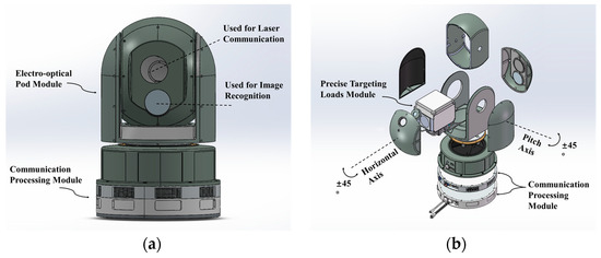
Figure 1.
Design of the high-precision FSO communication system for mobile platforms. The precise targeting load module is located in the spherical turret of the electro-optical pod module. The spherical turret has image recognition, can be rotated ±45° around the horizontal axis, and covers ±45° of field of view in the pitch flat. (a) Overall appearance of the system. (b) Explosion view of the system.
The electro-optical pod can acquire the target through image recognition in the field of view according to the scan-specified path, complete rough alignment of the visual axis, and extract light spot information. Immediately after initial capture is completed, a laser beam will pass through the upper window of the electro-optical pod module into the precise targeting load module. Precise targeting loads first collect the laser spot information through an internal sensor and calculate the offset of the visual axis. Based on the offset of the visual axis at the current moment, the offset at the next moment will be predicted. Then, coarse and precise structures are controlled to compensate for the offset every 20 ms. Finally, high-precision alignment of the visual axis is realized, and stable communication of the spatial optical link is guaranteed.
Figure 2 shows the design of the precise targeting load module. The module adopts a transceiver coaxial design. As shown in Figure 3, receiving and transmitting optical paths share a primary mirror system, and they are separated and coupled through dichroic mirrors. The design of the primary mirror system is shown in Figure 4a using the Ritchey–Chretien (R–C) afocal telescope. Figure 4b shows the design of the tubular folding optical path inside the module. All optical components are folded around the R–C primary mirror, effectively reducing the volume and weight of the load.
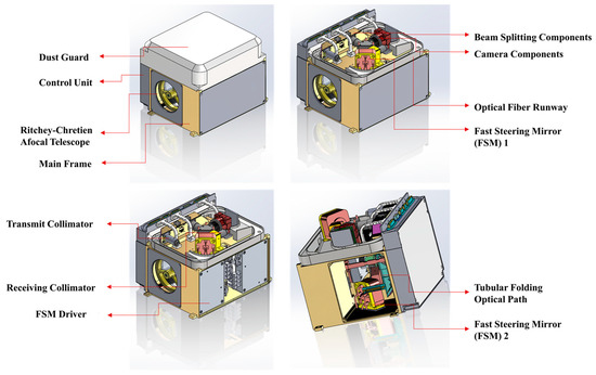
Figure 2.
Design of precise targeting loads module.

Figure 3.
Transceiver block diagram of precise targeting loads module.
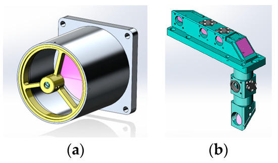
Figure 4.
(a) Design of primary mirror system. (b) Design of tubular folding optical path.
The R-C primary mirror is coaxial with the upper window of the electro-optical pod, which is used for optical communication (shown in Figure 3). R-C telescope system concentrates on receiving beam and diverges transmitting beam. Both FSM and planar reflectors are used to turn optical paths. In addition, FSM can adjust the direction of the optical path. Dichroic mirrors are highly reflective of the receiving beam and highly transparent to transmitting light. A beam splitter separately divides a part of receiving light to CCD for collecting spot offset. The control unit will adjust the deflection angle of FSM1 (precise sight) and the deflection angle of the electro-optical pod (coarse sight) according to this spot offset.
As shown in Figure 3, inside the precise targeting loads module, the received light is first focused by the RC telescope system and then then changed direction through FSM1. After that, part of the receiving beam is split to the CCD for collecting the optical axis offset when passing through the beam splitter. The rest of the beam passes through the planar reflector to change the direction again, is reflected to the FSM2 mirror in the dichroic mirror, and finally enters the collimator at the receiving end after adjusting the direction by FSM2. The transmitting optical path also adopts the same optical path structure. However, the direction of the transmit beam is not changed by the dichroic mirror, and it is not divided by the beam splitter. Therefore, the transmitting light diverges through the RC telescope system after changing the light path direction twice by the planar reflector and FSM1.
3. Prototype of FSO Communication System for Mobile Platform
According to the system design introduced in Section 2, Figure 5 and Figure 6 show the prototype of the FSO communication system for mobile platforms. Table 1 shows the link budget of the system. When the communication distance is 2 KM, the beam divergence angle is 1 mrad, and the receiving diameter is 60 mm, the geometric loss caused by transmission is 36 dB. After considering the atmospheric transmission loss and the transmit–receive coupling loss, the system also has a link margin of 12 dB, which fully meets the needs of kilometer-level communication.
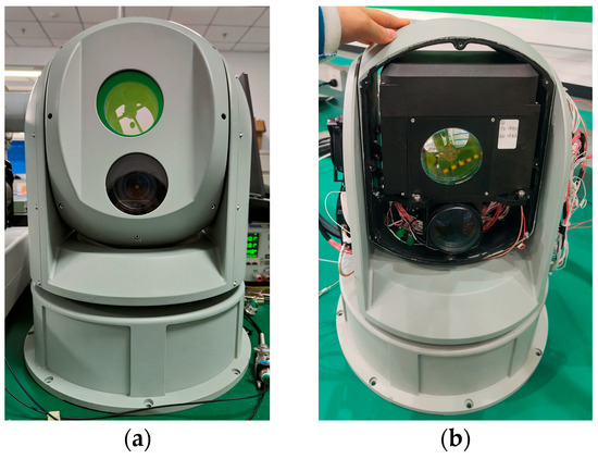
Figure 5.
(a) Prototype of FSO communication system: front view. (b) Prototype of FSO communication: interior view.

Figure 6.
(a) Prototype of precise targeting load module: front view. (b) Prototype of precise targeting loads module: top view. (c) Prototype of tubular folding optical path: front view.

Table 1.
Link budget of system.
Table 2 shows the prototype specifications. Due to the design of the common aperture transceiver, the wavelength of receiving light is different from the transmitting light for the same laser communication device in order to avoid receiving data sent by itself. At the same time, in order to ensure normal communication between devices at both ends, the transmitting wavelength of the device at the opposite end is the same as the receiving wavelength of the device at the local end. The transmitted optical power through high-power EDFA is optimal at +33 dBm (this value can be changed by configuration EDFA up to +35 dBm), and the received optical power is at a minimum of −30 dBm. The precision sight structure has a tracking range of ±26.2 mrad, consistent with the field of view of FSM. The coarse sight structure has a tracking range of ±785.4 mrad, consistent with the field of view of the electro-optical pod. The divergence angle of the laser emitted by the system is 0.5 mrad. The R-C telescope system has a primary mirror diameter of 60 mm, a primary mirror multiple of 10, and a secondary mirror diameter of 12 mm. The field of view of the camera is 3 mrad, and the diameter of the spot on the CCD target surface is 100 um. The angular resolution and the angular acceleration of FSM are 2.4 urad and 10000 rad/s², and the mirror reflectivity is greater than 99.5%. Therefore, FSM can change the direction of the optical path with low loss and quickly compensate for optical axis offset.

Table 2.
Prototype specifications.
The design of the tubular folding optical path increases the difficulty of coaxial alignment, so we need to carry out coaxial calibration of the system after prototype assembly is completed. Firstly, the assembly error will lead to the tube light path not being coaxial and the situation that the electro-optical pod is not coaxial with a precise targeting load. To solve this problem, we use a parallel light tube, a rotating platform, and a gasket to carry out the first step of coaxial adjustment. Secondly, the receiving end is not coaxial with the tube optical path. In the calibration and debugging phase, we adjust the beam angle by controlling FSM2 to ensure that the tube optical path is coaxial with the receiving end. This angle information is written into the parameter package as the calibration origin of the FSM2, so that the receiving end will be aligned once the system is turned on. In addition, there are sensors at the receiving end for collecting light intensity information. The control module will calculate the FSM2 control instructions in real time according to the collected light intensity information [17], so as to avoid the constant drift of FSM2 and ensure the coaxial axis of the receiving end.
Finally, there is translation and rotation when the camera is assembled, so there is rotation deviation θ and translation deviation between the camera coordinate system and the precise targeting load coordinate system (that is, the FSM1 coordinate system). This relationship can be expressed by the following formulas:
Therefore, we can use the parameter array to describe this deviation. In addition, since the spot deforms at the edge of the camera, the deformation can also be corrected according to the coordinate translation and rotation. Hence, we block the camera’s field of view, and each module uses a different array of parameters to correct for errors caused by translation, rotation, and distortion. In the case of an external light source, we control the FSM1 to carry out two-dimensional periodic motion in small steps to scan the entire field of view of the camera. As shown in Figure 7, we will obtain the spot coordinates that correspond one-to-one to the FSM1 coordinates, which are calculated from the spot information collected by the camera. The parameter array of error correction can be obtained after nonlinear curve fitting for the data of different modules. During the tracking process, we will use the FPGA in the control unit to calculate corrected spot coordinates in real time through the correction array, which will correct the positioning bias of the camera. As shown in Figure 8, after correcting the spot coordinates collected by the camera, the positioning error of the camera edge is greatly reduced, and the positioning overall error of the camera is reduced by one order of magnitude. In the above way, we completed the coaxial calibration of the camera system for beam positioning. Thus far, the coaxial debugging of the whole system has been completed.
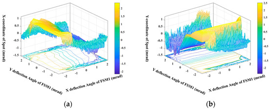
Figure 7.
Spot coordinates obtained when FSM1 scans the entire camera field of view in periodic motion; below the surface is a contour line of spot coordinates. (a) Spot x-coordinate surface plot. (b) Spot y-coordinate surface plot.
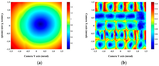
Figure 8.
(a) Camera positioning error without correction. (b) Camera positioning error after matrix correction.
4. Field Experiments
We did field experiments in 2023 to prove that our system is feasible. Before the tracking experiment of the moving platform, we first did the preliminary experiments of single-ended swing tracking under static platform conditions. The two sets of FSO communication systems are placed at two ends 20 m apart. Under the conditions of initial alignment, the transmitter device is controlled to swing periodically between two points with different horizontal and vertical coordinates. At the receiving end, the CCD of the system collects spot off-target position information at a frequency of 200 HZ; FSM1 and the electro-optical pod compensate this spot offset at a frequency of 200 HZ and 50 HZ, respectively.
Figure 9 shows the results of tracking experiments under single-end swing conditions. When the transmitter device swings periodically between two fixed orientations, the coordinates of the receiver device also swing periodically between two fixed orientations under the control of the tracking program in order to align with the transmitter all the time (Figure 9a,b). In the whole process mentioned above, the value of spot off-target collected by CCD at the receiving end is within ±0.6 mrad (Figure 9c,d), that is, the receiver points to the transmitter correctly during the entire single-end swing experiment. In addition, the value of spot off-target is stable within ±0.3 mrad most of the time, and the value greater than ±0.3 mrad appears in the form of periodic burrs. This is because when the position of the transmitter changes, the position of the spot collected by the CCD of the receiver will also appear to have a large offset. In addition, an overshoot phenomenon will occur when FSM1 and the electro-optical pod are controlled to compensate for the offset. Therefore, with the periodic position of the transmitter, the spot-off-target position collected by CCD also appears periodic burrs.
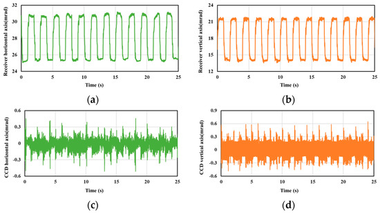
Figure 9.
Horizontal and vertical data are measured simultaneously in single-ended swing tracking experiments. (a) Horizontal direction of receiving device. (b) Vertical direction of receiving device. (c) Horizontal coordinates of spots collected by CCD. (d) Vertical coordinates of spots collected by CCD.
After the static tracking experiment, we carried out a dynamic experiment with the cart. Figure 10 shows the dynamic experiment on the cart. Two sets of the FSO communication systems were placed on carts 100 m apart. The signal sent by the transmitter is a pseudo-random code generated by the FPGA and encoded using 8 B/10 B code to prevent channel vacancy duration. After the systems are turned on, the carts are kept still, and the system at both ends will automatically scan and align with the opposite system under the control of the tracking program. When the optical power at both ends is stable and the system can communicate normally, it indicates that the two devices are successfully aligned. After that, the cart at the transmitter remains motionless, and the cart at the receiver is pushed back and forth to test the dynamic tracking performance of the system.
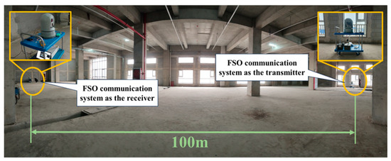
Figure 10.
Dynamic tracking experiment using cart.
Figure 11 shows the test results of the receiver system in the dynamic tracking experiment on the cart. It can be seen from the figure that due to the movement of the cart, the FSOC system must change the direction of the beam to ensure alignment of the optical link at both ends, so the coordinates of the receiver system change with the movement of the cart. The change trend of the horizontal coordinate is consistent with the movement trend of the cart first pushing forward and then pulling back. According to the change of horizontal coordinate and the duration of change in Figure 11a, the average speed of cart in two dynamic processes can be calculated as 2.11 m/s and 1.85 m/s, respectively. During the experiment, because the ground is relatively flat, the change of vertical coordinates is caused by the vibration noise in the movement, so its amplitude is small, and the overall change trend is not large. The spot offset obtained by CCD is within ±1 mrad (Figure 11c,d). Compared with the experiments of single-ended swing tracking, the spot offset in the dynamic tracking experiment is significantly increased; that is, the system alignment accuracy is reduced. This is caused by the dynamic lag error and vibration error introduced in the movement of the platform.
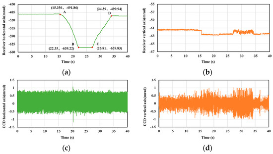
Figure 11.
Horizontal and vertical data are measured simultaneously in tracking experiments between moving platforms. (a) Horizontal direction of receiving device. (b) Vertical direction of receiving device. (c) Horizontal coordinates of spots collected by CCD. (d) Vertical coordinates of spots collected by CCD.
Figure 12 shows the data collected by the photoelectric detector in dynamic tracking. This value is positively correlated with the light intensity received by the system. It can be seen from the figure that the fluctuation range of the collected data is only about 3 dB, that is, the light intensity fluctuation in the dynamic tracking process is less than 3 dB, so the intensity fluctuation caused by the dynamic tracking process has little impact on the system performance. Figure 13 shows the eye diagram in dynamic tracking. The fluctuation of optical power due to the alignment error in the tracking process will lead to the deterioration of the signal-to-noise ratio (SNR). This problem can be solved by designing specific algorithms or adding filters of specific frequencies to hardware. Due to the difficulty of the design and engineering application of the adaptive Zoom FSO Communication System, the typical space-borne optical communication system is fixed focus design. Typical space-borne optical communication systems are designed with fixed focus optics. In fact, the divergence angle, communication distance, transmitting power, and signal-receiving processing algorithm of the FSOC system jointly determine the bit error rate (BER) and SNR of the system. However, theoretically, under the same conditions, the larger the divergence angle, the more serious the deterioration of the system SNR and BER.
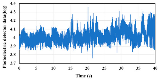
Figure 12.
Data collected by photoelectric detector in dynamic tracking.
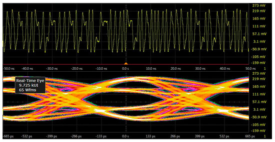
Figure 13.
Eye diagram of tracking experiments between mobile platforms.
We also did a vehicle-mounted experiment, but it failed. On the one hand, in the tracking process, the control unit of the system will predict the position of the light spot at the next time according to the current collected spot position data to achieve low error compensation. However, in the process of the dynamic test, the lateral vibration amplitude of the vehicle is large because the vehicle cannot drill holes to install shock absorbers. The vibration in the motion of the vehicle is completely random. It cannot be compensated by prediction but also increases the error of the original spot prediction position as noise. All these lead to the deterioration of the tracking performance of the system. On the other hand, due to the limitation of the experimental site, the communication distance is relatively close, and the relative motion speed is relatively large, which makes it easy for the spot to break away from CCD’s target surface and make tracking fail.
We are now improving the system to achieve a longer distance tracking alignment and link communication of the FSO communication system under vehicle-mounted experimental conditions. In order to expand the application scenarios and conditions of the system in the future, we will also study the influence of the complex atmospheric environment on the performance of laser communication systems and its improvement methods.
5. Conclusions
We developed a new free-space optical communication system between moving platforms with a unique tubular folding optical path design and tracking mechanism. Our prototype achieved high-precision targeting and tracking on the mobile platform. On a moving platform, the tracking error within 100 m distance is less than 1 mrad. In the current prototype design stage, the weight of the precise targeting load module is 4 KG, and the total weight of the system is 10 KG. We believe that this system is expected to provide stable communication links between vehicle platforms and for two-way link connections between high-altitude mobile platforms and ground.
Author Contributions
Conceptualization, N.S.; hardware, Y.W. (Yuehui Wang); software, N.S.; validation, N.S. and J.L.; writing—original draft preparation, N.S.; writing—review and editing, N.S. and Y.W. (Yuanda Wu); project administration, J.L. All authors have read and agreed to the published version of the manuscript.
Funding
This research received no external funding.
Institutional Review Board Statement
Not applicable.
Informed Consent Statement
Not applicable.
Data Availability Statement
Data are contained within the article.
Acknowledgments
The authors would like to thank the State Key Laboratory on Integrated Optoelectronics, the Institute of Semiconductors, the Chinese Academy of Sciences, and the School of Integrated Circuits, the Chinese Academy of Sciences.
Conflicts of Interest
The authors declare no conflicts of interest. The funders had no role in the design of this study, in the collection, analysis, or interpretation of data, in the writing of the manuscript, or in the decision to publish the results.
References
- Chan, V.W.S. Free-space optical communications. J. Lightw. Technol. 2006, 24, 4750–4762. [Google Scholar] [CrossRef]
- Alkholidi, A.G.; Altowij, K.S. Free Space Optical Communications—Theory and Practices, Contemporary Issues in Wireless Communications; InTech: Houston, TX, USA, 2014; pp. 159–212. [Google Scholar]
- Huang, Z.; Wang, Z.; Huang, M.; Li, W.; Lin, T.; He, P.; Ji, Y. Hybrid optical wireless network for future SAGOintegrated communication based on FSO/VLC heterogeneous interconnection. IEEE Photonics J. 2017, 9, 7902410. [Google Scholar] [CrossRef]
- Li, L.; Geng, T.; Wang, Y.; Li, X.; Wu, J.; Li, Y.; Ma, S.; Gao, S.; Wu, Z. Free-space optical communication using coherent detection and double adaptive detection thresholds. IEEE Photonics J. 2019, 11, 7900217. [Google Scholar] [CrossRef]
- Izadpanah, H.; ElBatt, T.; Kukshya, V.; Dolezal, F.; Ryu, B.K. High-availability free space optical and RF hybrid wireless networks. IEEE Wirel. Commun. 2003, 10, 45–53. [Google Scholar] [CrossRef]
- Khalighi, M.A.; Uysal, M. Survey on Free Space Optical Communication: A Communication Theory Perspective. IEEE Commun. Surv. Tutor. 2014, 16, 2231–2258. [Google Scholar] [CrossRef]
- Bloom, S.; Korevaar, E.; Schuster, J.; Willebrand, H. Understanding the performance of free-space optics [invited]. J. Opt. Netw. 2003, 2, 178–200. [Google Scholar] [CrossRef]
- He, J.; Norwood, R.A.; Brandt-Pearce, M.; Djordjevic, I.B.; Cvijetic, M.; Subramaniam, S.; Himmelhuber, R.; Reynolds, C.; Blanche, P.; Lynn, B.; et al. A survey on recent advances in optical communications. Comput. Elect. Eng. 2014, 40, 216–240. [Google Scholar] [CrossRef]
- Glushko, B.; Kin, D.; Shar, A. Gigabit optical wireless communication system for personal area networking. Opt. Mem. Neural Netw. 2013, 22, 73–80. [Google Scholar] [CrossRef]
- Ghassemlooy, Z.; Popoola, W. Terrestrial Free-Space Optical Communications; INTECH Open Access: Rijeka, Croatia, 2010. [Google Scholar]
- Kaymak, Y.; Rojas-Cessa, R.; Feng, J.; Ansari, N.; Zhou, M.; Zhang, T. A Survey on Acquisition, Tracking, and Pointing Mechanisms for Mobile Free-Space Optical Communications. IEEE Commun. Surv. Tutor. 2018, 20, 1104–1123. [Google Scholar] [CrossRef]
- Harris, A.; Sluss, J.J.; Refai, H.H.; LoPresti, P.G. Alignment and tracking of a free-space optical communications link to a UAV. In Proceedings of the 24th Digital Avionics Systems Conference, Washington, DC, USA, 30 October–3 November 2004; pp. 1.C.2–1.1. [Google Scholar]
- Kumari, M.; Sharma, A.; Chaudhary, S. High-Speed Spiral-Phase Donut-Modes-Based Hybrid FSO-MMF Communication System by Incorporating OCDMA Scheme. Photonics 2023, 10, 94. [Google Scholar] [CrossRef]
- Esmail, M.A. Performance Monitoring of Hybrid All-Optical Fiber/FSO Communication Systems. Appl. Sci. 2023, 13, 8477. [Google Scholar] [CrossRef]
- Graham, C.; Bramall, D.; Younus, O.; Riaz, A.; Binns, R.; Scullion, E.; Wicks, R.T.; Bourgenot, C. Steering Mirror System with Closed-Loop Feedback for Free-Space Optical Communication Terminals. Aerospace 2024, 11, 330. [Google Scholar] [CrossRef]
- Urabe, H.; Haruyama, S.; Shogenji, T.; Ishikawa, S.; Hiruta, M.; Teraoka, F.; Arita, T.; Matsubara, H.; Nakagawa, S. High data rate ground-to-train free-space optical communication system. Opt. Eng. 2012, 51, 031204. [Google Scholar] [CrossRef]
- Sun, N.; Wang, Y.; Zhu, H.; Zhang, J.; Du, A.; Wang, W.; Zhao, Y.; Liu, J. Self-Alignment FSOC System with Miniaturized Structure for Small Mobile Platform. IEEE Photonics J. 2022, 14, 7357506. [Google Scholar] [CrossRef]
- Carrasco-Casado, A.; Vergaz, R.; Sánchez-Pena, J.M.; Otón, E.; Geday, M.A.; Otén, J.M. Low-impact air-to-ground free-space optical communication system design and first results. In Proceedings of the 2011 International Conference on Space Optical Systems and Applications (ICSOS), Santa Monica, CA, USA, 11–13 May 2011; pp. 109–112. [Google Scholar]
- Guelman, M.; Kogan, A.; Kazarian, A.; Livne, A.; Orenstein, M.; Michalik, H. Acquisition and pointing control for inter-satellite laser communications. IEEE Trans. Aerosp. Electron. Syst. 2004, 40, 1239–1248. [Google Scholar] [CrossRef]
- Hiruta, M.; Nakagawa, M.; Haruyama, S.; Ishikawa, S. A study on optical wireless train communication system using mobile object tracking technique. In Proceedings of the 2009 11th International Conference on Advanced Communication Technology, Gangwon, Republic of Korea, 15–18 February 2009; pp. 35–40. [Google Scholar]
- Fahs, B.; Romanowicz, M.; Kim, J.; Hella, M.M. A self-alignment system for LOS optical wireless communication links. IEEE Photonics Technol. Lett. 2017, 29, 2207–2210. [Google Scholar] [CrossRef]
Disclaimer/Publisher’s Note: The statements, opinions and data contained in all publications are solely those of the individual author(s) and contributor(s) and not of MDPI and/or the editor(s). MDPI and/or the editor(s) disclaim responsibility for any injury to people or property resulting from any ideas, methods, instructions or products referred to in the content. |
© 2024 by the authors. Licensee MDPI, Basel, Switzerland. This article is an open access article distributed under the terms and conditions of the Creative Commons Attribution (CC BY) license (https://creativecommons.org/licenses/by/4.0/).