Article

Asymmetric Shaping for Ultrafast Elliptical Bessel-like Beams

Laboratoire Hubert Curien, UMR 5516 CNRS, Université Jean Monnet, 42000 Saint Etienne, France
*
Author to whom correspondence should be addressed.
Current address: CNRS, LP3 UMR 7341, Aix-Marseille University, 13288 Marseille, France.
Photonics 2023, 10(6), 651; https://doi.org/10.3390/photonics10060651
Submission received: 5 May 2023 / Revised: 28 May 2023 / Accepted: 2 June 2023 / Published: 5 June 2023

Abstract

:
The generation of an elliptical Bessel–Gauss beam has become a topic of interest in ultrafast laser processing of transparent materials because of its nearly non-diffractive elliptical central core. These beams can show potential in generating anisotropic structures down to the nanoscale and in producing asymmetries in the induced fields of thermo-mechanical constraints relevant for material structuring. However, maintaining the central core ellipticity is a challenge that requires further analysis, notably in the propagation behavior of phase anisotropies during the conical interference. This paper presents the controlled generation and propagation of a highly elliptical Bessel–Gauss beam using asymmetric phase-modulation technique. The study involves engineering different asymmetric phase holograms and analyzing their performances in terms of the non-diffractive property and uniformity of the generated beams. We indicate the presence in specific cases of diffraction and its influence on the invariance of the beam shape. The simulation results are in excellent agreement with the experimental results, which verifies the accuracy and reliability of our approach.

1. Introduction

In the last few decades, the implementation of the ultrafast Bessel–Gauss (BG) beam has had a significant impact on the field of laser-material processing. With an extended depth of focus, the non-diffractive central core of the focused micro-BG beam facilitates highly stable non-linear ionization with axial energy confinement [1,2,3,4]. All these characteristics enable the fabrication of high-aspect-ratio nanostructures, ultra-precision laser machining, drilling, and cutting applications [5,6,7,8,9]. An axicon (conical lens or phase) is the most convenient means to realize a BG beam and has been employed in various applications [10,11,12,13,14,15]. Recent studies suggest that the non-ideal axicon phase can result in peculiar intensity patterns [16,17,18], including the elliptical BG beam, which has potential in a wide range of applications [19,20].
In laser processing applications, the elliptical BG beam has recently become a topic of interest. The elliptical central core of this asymmetric beam accompanied by side multichannels makes it an attractive tool in the fabrication of ultra-high-aspect-ratio multi-nano-channels and material cleaving with sub-micron precision [21,22], and also facilitates intra-volume material modification [19]. Such elliptical beams have also previously shown their ability to determine asymmetric stress field with preferential crack orientation, guiding cleavage and fracture planes to facilitate cutting of transparent materials [23,24]. In this context, maintaining the central core ellipticity of these asymmetric beams is a challenging task and plays an important role in achieving uniform modifications and crack orientations.
The realization of an elliptical BG beam requires beam-shaping solutions. Several beam-shaping techniques are noted for the generation of such asymmetric beams, which are mostly dedicated to either using the tilted axicon [17,22,25,26] or the amplitude masks [21,24]. Another technique to produce useful asymmetric beam patterns is implementing the generalized axicon, the combination of a radially symmetric axicon phase and an azimuthally dependent arbitrary phase, retrieved by optimizing with respect to the desired optical beam profile [23]. In the case of a tilted axicon, the oblique incident plane of the axicon introduced asymmetry to the conical phase and hence generates the elliptical BG beam. The main limitation of this technique is the presence of astigmatic aberration and the misaligned optic axis where the axicon has to be laterally shifted precisely to maintain the generated beam profiles [27]. The amplitude filers, such as a rectangular-shaped filter [21] and an hourglass-shaped filter (H-amp) [24], can generate an elliptical BG beam by partially blocking the Bessel ring at the back focal plane (also known as Fourier plane) of the lens in the axicon-lens assembly without disturbing the optic axis of the beam. The dimensions of the amplitude filters define the ellipticity of the generated beam. However, amplitude filtering is inherently a loss of energy.
Recently, there has been a quest to attain the most convenient technique for the controlled generation of elliptical BG beams with non-diffractive central core. The phase-only solution including asymmetric elements represents a promising path to conserve energy. A particularly robust solution conserving ellipticity over a long distance was implemented in Chen et al. [28], corresponding to an hourglass (H) phase designed to compensate diffraction along the axial lobe. From a general point of view, it is then of interest to investigate the propagation of asymmetric phase elements superposed on the conical phase pattern, starting with the simplest rectangular elements and their influence on the stability, asymmetry, and energy content of the beam. In this paper, we perform an in-depth study of the controlled generation of non-diffractive elliptical BG-like beams by computing different asymmetric phase-only computer-generated holograms (CGHs), displayed on a reflective-type phase-only LCOS-SLM (liquid crystal on silicon-based spatial light modulator) device for having precise control over phase parameters. We equally discuss the stability of different phase-modulated solutions and highlight the propagation dynamics of phase anisotropies. LCOS-SLM works in the principle of phase modulation, which spatially shapes the input laser beam to produce the desired output beam based on the gray-scale image of the CGH displayed on its screen [29]. We implement the blazed grating phase on the initially generated CGHs (for R- and H-phase, as discussed later) that can efficiently eliminate any optical noises at the Fourier plane and can produce uniform micro-elliptical BG-like beams (without partially blocking the Bessel ring). Subsequently, we analyze and present the performances of those modified CGHs in terms of the non-diffractive properties of the generated asymmetric beams. Furthermore, a numerical model based on the Fresnel transfer function method (FTFM) is developed to compare the experimentally obtained beam profiles. The excellent agreement of experimental results with simulation confirms the accuracy and reliability of the beam-shaping technique. This study will help to increase the efficiency and controllability of laser processing applications.

2. Theory

2.1. Formalism of Symmetric and Asymmetric BG Beam

The most commonly used optical element which facilitates the generation of a non-diffractive BG beam is the axicon, having a symmetric conical phase. As an exact solution of the free-space Helmholtz’s equation, the transverse electric field distribution of the BG beam is given by [1],
E ( r , ϕ , z ) = e x p ( i k z z ) J 0 ( k r r )
where J 0 ( k r r ) is the zeroth-order Bessel function of the first kind defining the transverse amplitude profile of the BG beam; k z = k c o s θ and k r = k s i n θ are the longitudinal and radial wave vector components, respectively (see Figure 1) with the condition k = k z 2 + k r 2 = 2 π λ ( λ is the center wavelength of the incident collimated laser beam); and r, ϕ and z are the radial, azimuthal, and longitudinal components of the cylindrical coordinate system, respectively.
Figure 1a shows the examples of phase asymmetries to be studied here, including circularly symmetric conical phase, and the asymmetric phases composed of a rectangular shaped in-phase filter (R-phase) and a hourglass-shaped in-phase filter (H-phase) that originates from the reverse engineering [21,24]. As depicted in Figure 1b, the formation of the symmetric BG beam is a result of interference of a set of plane waves whose wave-vectors (k) all lie on the surface of a cone, thus maintaining the same half-conical angle, i.e., θ = tan 1 ( k r / k z ) , with respect to the axis of propagation (z).
In the free space, the on-axis intensity evolution of the BG beam as a function of the propagation distance (z) can be evaluated using the stationary phase approximation of Fresnel diffraction integral [5]:
I ( r = 0 , z ) = 8 π P 0 z sin 2 θ λ ω 0 2 e x p 2 z sin θ ω 0 2
where ω 0 is the beam-waist of the incident laser beam that defines the non-diffractive Bessel length ( z m a x = ω 0 / tan θ ) of the BG beam, and P 0 is the peak power of the incident laser pulse. The parameter θ is related to the base angle ( α ) of a thin axicon [30], which determines the spot size ( W F W H M 2.27 / k s i n θ ) of the BG beam defined as the full width at half maxima (FWHM) of the central peak in the transverse intensity profile [31].
For the generation of elliptical BG beams, we utilize the physical properties of the reported amplitude masks [21,24], and systematically engineer asymmetric conical phases (termed as R- and H-phase) using a similar methodology described in Jenne et al. [23]. The asymmetric phases (see Figure 1a) containing R- and H-phase filters of variable dimensions give rise to a certain set of direct plane waves produced by the in-phase filtered region after the laser illumination. This particular set of plane waves, as indicated in Figure 2 (see red dotted lines), does not lie on the conical surface of interference, but rather lies parallel to the optical axis. The absence of these direct waves along the conical surface creates certain asymmetry in the process of interference (i.e., superposition of plane waves arising from the non-filtered region of the asymmetric phases), particularly responsible for the elliptical BG beam (with elliptical central core) formation.
The in-phase filters of the asymmetric phases (both R- and H-phase) directly interact with the central part of the input laser beam; thus, they introduce diffraction effects, the implication of which can be found in the Fourier plane (FP), as shown in Figure 2. As a combined effect of the asymmetric interference discussed before and the presence of diffraction introduces instability in the resulting elliptical BG beam, the ellipticity of the central core changes slowly as a function of the propagation distances which makes the resulting beam pseudo-non-diffractive.
It is observed with our developed numerical model (see Section 3) that the diffraction effect is significantly higher in the case of the R-phase, which not only produces central noise but also strongly modulates the Bessel ring as can be clearly seen in the angular spectrum representation (see Figure 2). However, this modulation effect is minimal in the case of the H-phase, which makes it a comparatively more effective tool in terms of closely maintaining the propagation invariant property of the generated elliptical BG beam, as discussed in Section 5. An advanced beam-shaping method using a blazed grating phase for eliminating the above-mentioned central noise (spatially separated at the FP, and hence filtered) is discussed later (see Section 4), and it is essential to make the final beam modulation free.
It is now important to point out that the generation of the elliptical BG beams by the asymmetric phases while maintaining the condition Δ R Δ ω ( Δ R and Δ ω represent spatial dimensions of the phase-aperture and input beam, respectively), follows the uncertainty relation given below:
Δ d R Δ z m a x = c . Δ e ( for R - phase ) Δ β H = c . Δ e ( for H - phase )
where c is the proportionality constant, Δ d R and Δ β H are the spatial width of the R-phase filter and the angular extension of the H-phase filter (more details are given further in the text) with respect to its center, respectively, Δ z m a x is the uncertainty of the Bessel length, and Δ e is the uncertainty of the central core ellipticity at the propagation distance (z) corresponding to peak on-axis intensity.
For a given input beam size ( Δ ω ), the Equation (3) implies that the ellipticity of the beam is directly proportional to the spatial dimensions of the in-phase filters (both R- and H-phase). The Bessel length ( Δ z m a x ) has an inverse relationship with the filter dimension ( Δ d R ) in the case of R-phase, whereas the Bessel length (only depends on the input beam size) is completely independent of the filter dimension ( Δ β H ) for H-phase. In the later sections, we exploit the generation of such elliptical BG beams both numerically and experimentally.

3. Numerical Modeling and Validation

This section emphasizes the generation of demagnified symmetric and asymmetric BG beams (in air) by numerical simulation. An algorithm based on FTFM method in scalar diffraction theory is developed, which is the theoretical basis for this simulation [32].
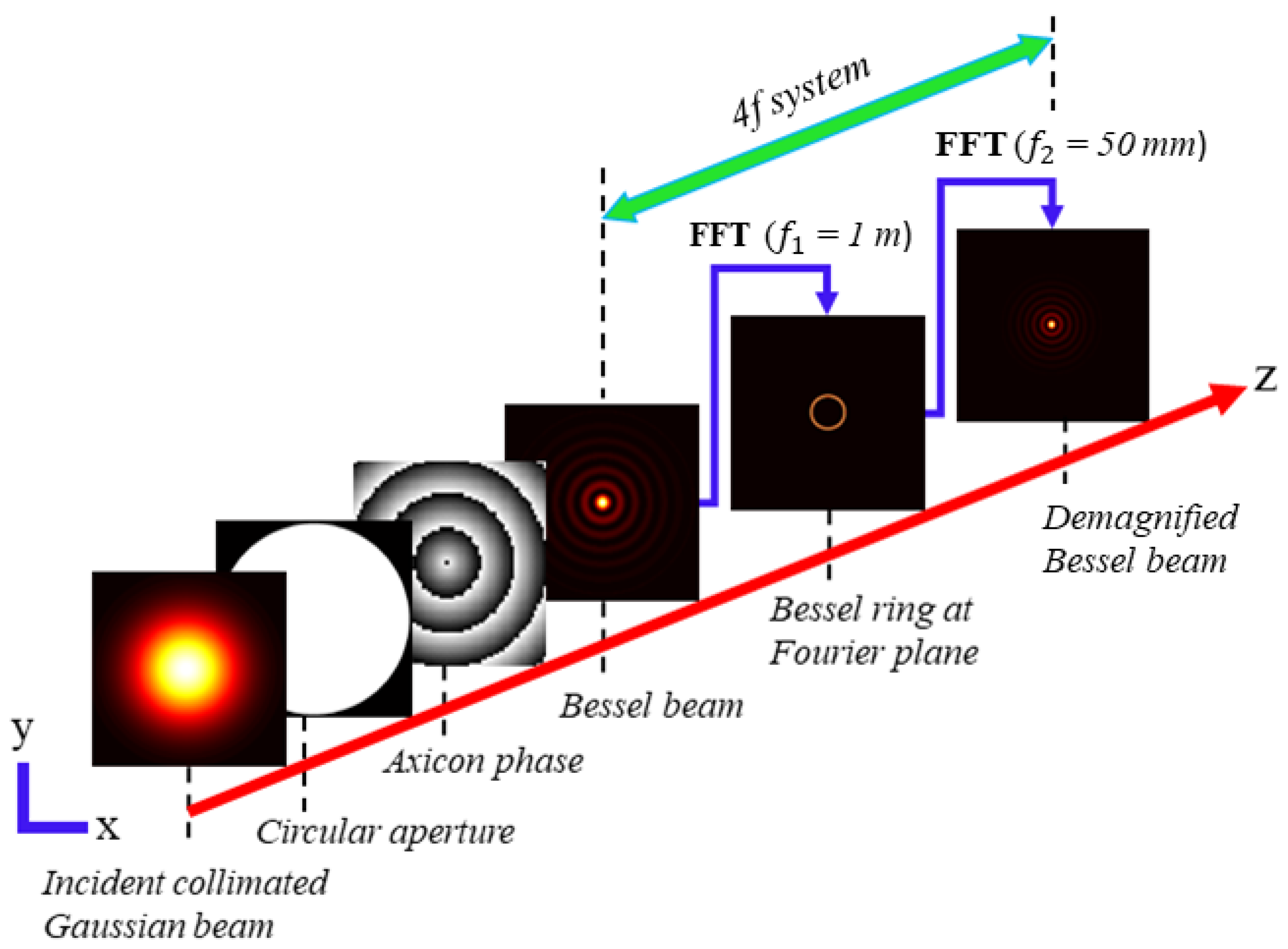
The schematic of the algorithm is depicted in Figure 3, representing the propagation of the Bessel beams (initially generated by the conical phases) through a telescopic 4f system. The 4f system is modelled in such a way that the initially generated BG beam behind the axicon phase is demagnified by a factor ( M = f 1 / f 2 ; f 1 = 1 m and f 2 = 50 mm are the focal lengths associated to the 4f-system) of 20 after the 4f propagation. Thus, a subsequent reduction of Bessel length is expected by a factor of M 2 . The calculating area of the object plane (at z = 0 ) is sampled with 1000 × 1000 pixel-grids with a pixel dimension of 10 μ m × 10 μ m throughout the simulation.
To solely realize the non-diffractive nature of the generated beam, the resulting final beam is reconstructed as a stack of slices parallel to the transverse (xy) plane, and hence extended along the propagation direction (z). The simulation is carried out completely in the spatial domain; therefore, there is no temporal influence of the input laser beam on the generated Bessel beams.

3.1. Reconstruction Method

To generate a symmetric BG beam, a thin axicon phase with α = 0.4 is considered on the object plane, which is illuminated with a collimated laser beam of beam-waist ω 0 = 0.93 mm (at 1/ e 2 ) at a given wavelength ( λ ) of 800 nm. The complex amplitude distribution just after the object plane can be obtained by
U ( x , y , z 0 ) = U 0 e x p x 2 + y 2 ω 0 2 T a ( x , y )
Here, U 0 is the amplitude of the input beam, T a ( x , y ) = e x p ( j ϕ a ) being the amplitude transmission function of a thin axicon with the axicon phase: ϕ a = k α ( n 1 ) ( x 2 + y 2 ) 1 / 2 .
Under the Fresnel approximation, the complex amplitude distribution of the output beam at a distance z from the axicon phase can be expressed by [32,33]
U ( x , y , z ) = U ( x , y , z 0 ) f z λ ( x , y , z )
where f z λ ( x , y , z ) e x p ( j k z ) j λ z e x p { j k 2 z ( x 2 + y 2 ) } , being the Fresnel’s impulse response function. Now, by taking Fourier transform on both side of the Equation (5) and then applying the inverse Fourier transform, we obtain the expression for computing the diffracted field (Bessel distribution) as the following:
U ( x , y , z ) = I F F T { F F T { U ( x , y , z 0 ) } H ( f x , f y , z ) }
where I F F T {} and F F T {} denote the inverse fast Fourier transform and the fast Fourier transform operators respectively; H ( f x , f y , z ) = e x p ( j k z ) e x p ( j π λ z ( f x 2 + f y 2 ) ) is referred to as the Fresnel transfer function associated to f z λ ; f x and f y are the spatial coordinates in the frequency domain.
Now, we numerically model a 4f optical system by considering thin lens approximation (i.e., far-field Fraunhofer approximation) by simply taking the Fourier transforms of the Equation (6) twice in order to solely realize the demagnified version of the diffracted field (i.e., U 4 f ( x , y , z ) ) corresponds to the initially obtained diffracted field (i.e., U ( x , y , z ) ), as depicted in Figure 3:
U 4 f ( x , y , z ) = F F T { F F T { U ( x , y , z ) } }
The first F F T operation in the above expression gives the angular spectrum distribution at the FP, while the second F F T operation calculates the demagnified field after the 4f system. It is essential to mention that the sampling interval does not remain the same in the far-field diffraction calculations. Thus, the sampling interval after performing the 4f propagation becomes [33]:
Δ x = f 2 λ L x Δ y = f 2 λ L y
where L x = N x Δ f x and L y = N y Δ f y are the spatial dimensions of the sampling window, and Δ f x = f 1 λ / L x and Δ f y = f 1 λ / L x are the sampling interval associated to the FP in the orthogonal directions, respectively. Similarly, L x = N x Δ x and L y = N y Δ y are the spatial dimensions of the sampling window associated with the object plane, and Δ x and Δ y are the corresponding sampling intervals. The terms N x and N y denote the pixel densities along the x and y axes, respectively.

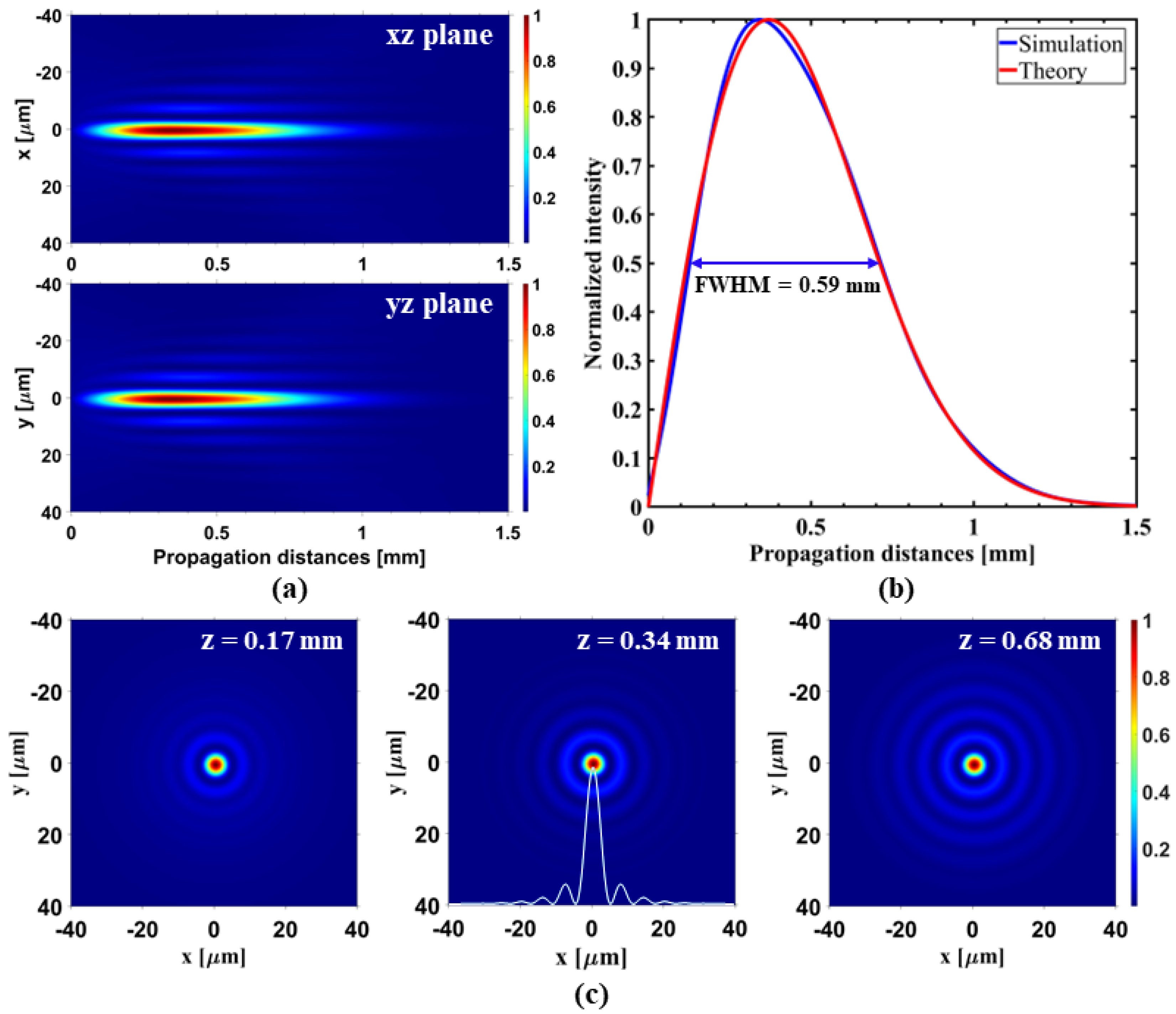
3.2. Reconstruction of Symmetric BG Beams

The implication of our numerical model results in the formation of a symmetric BG beam. Interestingly, the on-axis intensity profile of the resulting BG beam (after 4f propagation) with the non-diffractive Bessel length z m a x 0.59 mm (calculated at FWHM) profoundly matches the theoretical profile, as shown in Figure 4b.
Furthermore, the reconstructed longitudinal evolution of the resulting beam in the xz and yz planes (see Figure 4a) and its invariant central core sizes at different propagation distances (see Figure 4c) clearly indicates the non-diffractive ideal nature of the BG beam, and hence validates our numerical model.

3.3. Reconstruction of Asymmetric BG Beams

This section mainly focuses on the implementation of our developed numerical model to simulate the elliptical BG beams using different asymmetric phases (R- and H-phase). In the simulation, the ellipticity of the beam profiles is defined by the parameter e, which is calculated as the ratio of FWHM of the central core intensity along x and y axes (i.e., e = w x / w y ; where w x < w y ). Therefore, a smaller value of e corresponds to the higher ellipticity of a beam profile. Note that for simplicity, we use an annular filter in simulation to block the central noise in the FP (a beam-shaping technique to eliminate such optical noises is discussed later in the Section 4).

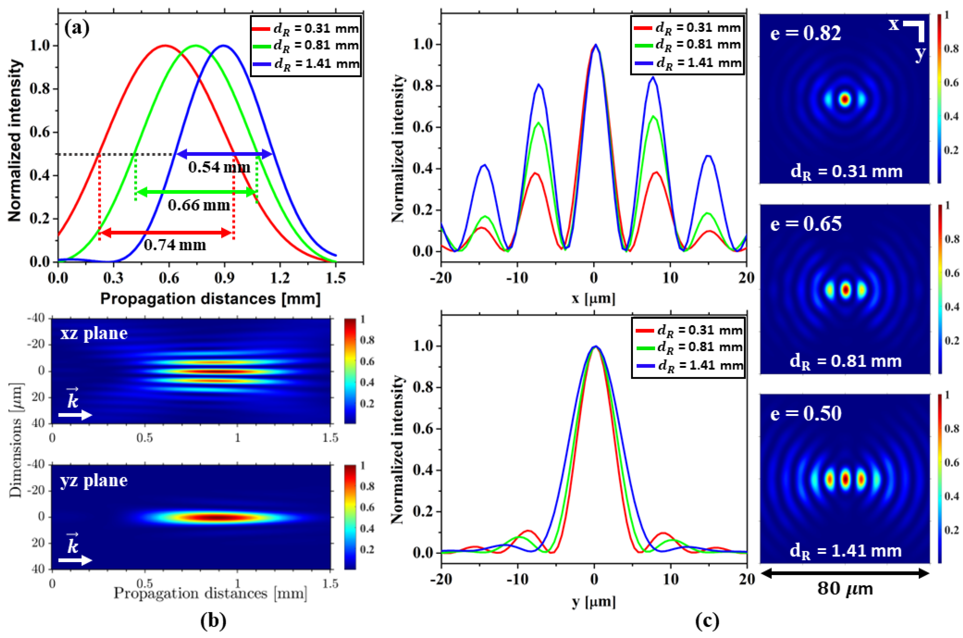
3.3.1. Numerical Analysis for R-Phase

Simulation is carried out for different in-phase filter dimensions ( d R ) of the R-phase (orientated along y axis). Figure 5a shows a notable change in the on-axis profile in comparison to the ideal-phase. Firstly, a successive decrease in the Bessel length ( z m a x 0.74 mm, 0.66 mm and 0.54 mm, respectively) along with a longitudinal shift of the on-axis profile is observed as the parameter d R increases. Secondly, an increased Bessel length ( z m a x = 0.74 mm) is noted for d R = 0.31 mm as compared to the ideal case (see Figure 4), which is surely the consequence of the modulated Bessel ring introduced by R-phase as discussed before.
Figure 5b shows the longitudinal intensity maps (in xz and yz planes) which verify the existence of an elliptical central core surrounded by the evolution (along x) of side multichannels. Figure 5c shows the images of the beam profiles for different d R values and the corresponding transverse intensity distributions (along x and y) at different peak on-axis intensity positions. It is observed that the ellipticity of the central core increases with d R (for d R = 0.31 mm, 0.81 mm, and 1.41 mm, the obtained value of e = 0.82, 0.65, and 0.50, respectively).

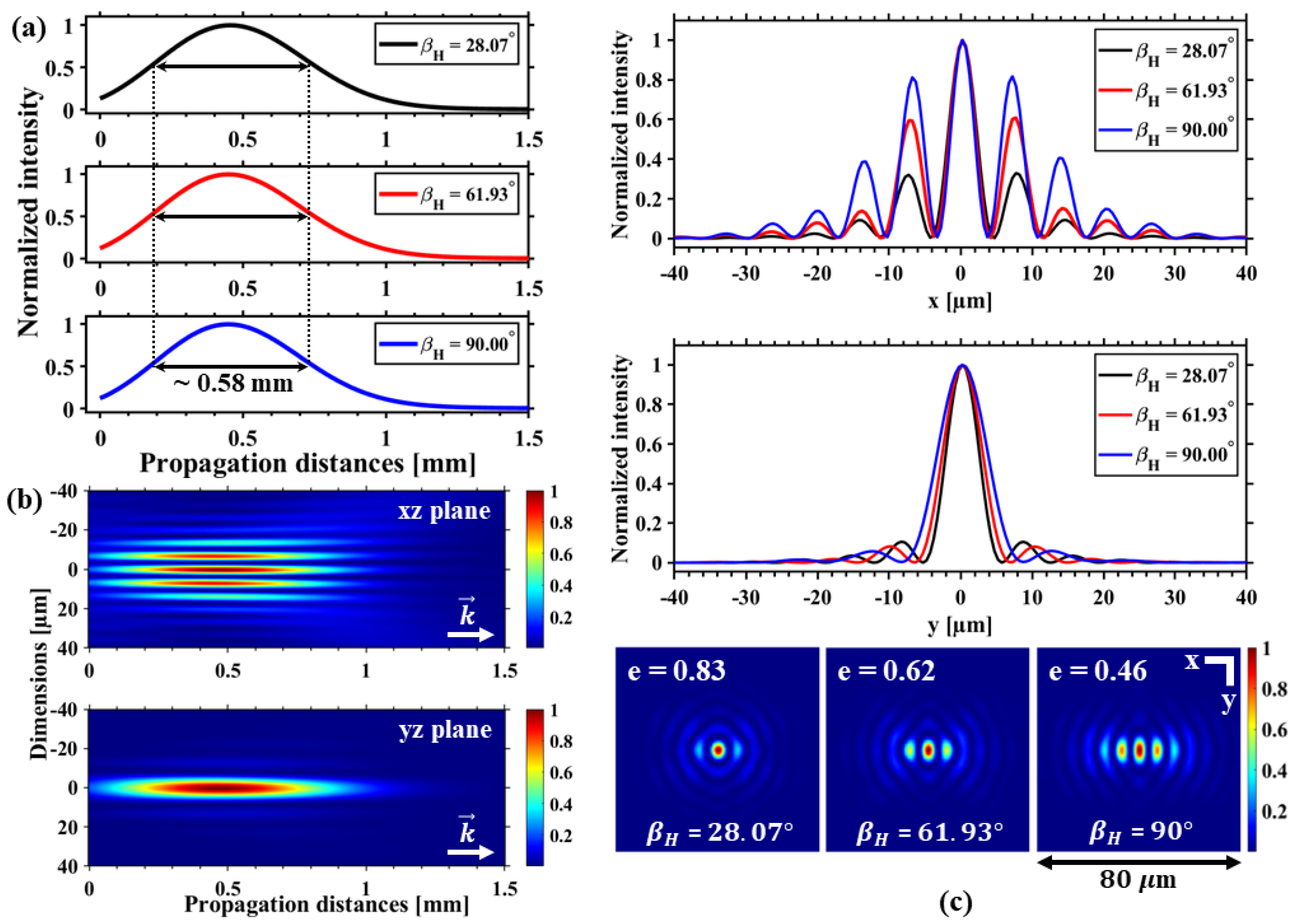
3.3.2. Numerical Analysis for H-Phase

Simulation is carried out for different in-phase filter dimensions ( β H ) of the H-phase. A maintained Bessel length of z m a x 0.58 mm is observed (see Figure 6a) for different values of β H (oriented along y axis). Interestingly, in contrast to the R-phase, the H-phase shows no longitudinal shift of the on-axis profile as β H increases. Figure 6b shows the longitudinal intensity maps (in xz and yz planes), which indicates an elliptical central core surrounded by the evolution (along x) of side multichannels. Figure 6c shows the images of the beam profiles for different β H values and the corresponding transverse intensity distributions (along x and y) at the peak on-axis intensity position (at z = 0.45 mm, same for all β H ). An increase in ellipticity is observed with β H (for β H = 28.07 , 61.93 , and 90 , the obtained value of e = 0.83, 0.62, and 0.46, respectively).
Finally, our numerical analyses reveal the influences of the asymmetric R- and H-phase in the formation of elliptical BG beams and systematically support the mathematical interpretations as shown in Equation (3), which validates our approach. In principle, if the rectangular (R) phase modulation produces along propagation a propagation variant effect, the H-phase compensates this, as the radial variability of the phase pattern compensates the evolution along the axis.

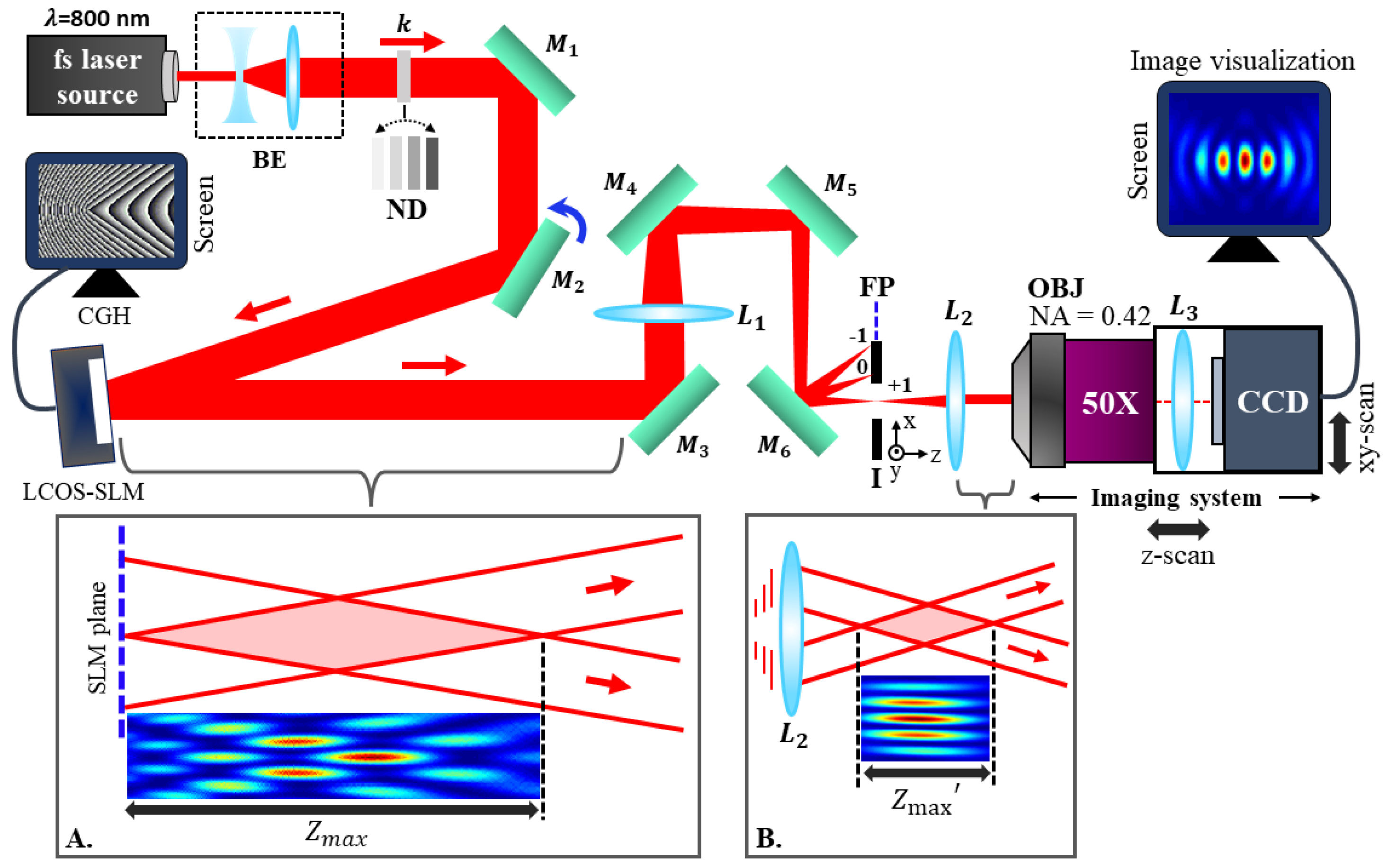
4. Experimental Setup and Methods for Beam-Shaping

The experimental setup for the generation of the elliptical BG beams is shown in Figure 7. The laser pulse (pulse duration ∼ 110 fs, repetition rate ∼ 50 MHz) originated from a femtosecond laser oscillator (IMRA/femtolite, FX-10-STD) at 800 nm wavelength is expanded and perfectly collimated using a beam expander setup containing a concave lens and a plano-convex lens (PCL) of focal lengths −25 mm and 75 mm, respectively. The energy of the laser beam is adjusted using a set of calibrated neutral density (ND) filters and hence directed (using the dielectric mirrors M 1 and M 2 ) to the active area (screen) of the reflective type phase-only LCOS-SLM device (X10468 series, Hamamatsu Photonics, Shizuoka, Japan) at a low angle of incidence (∼8 
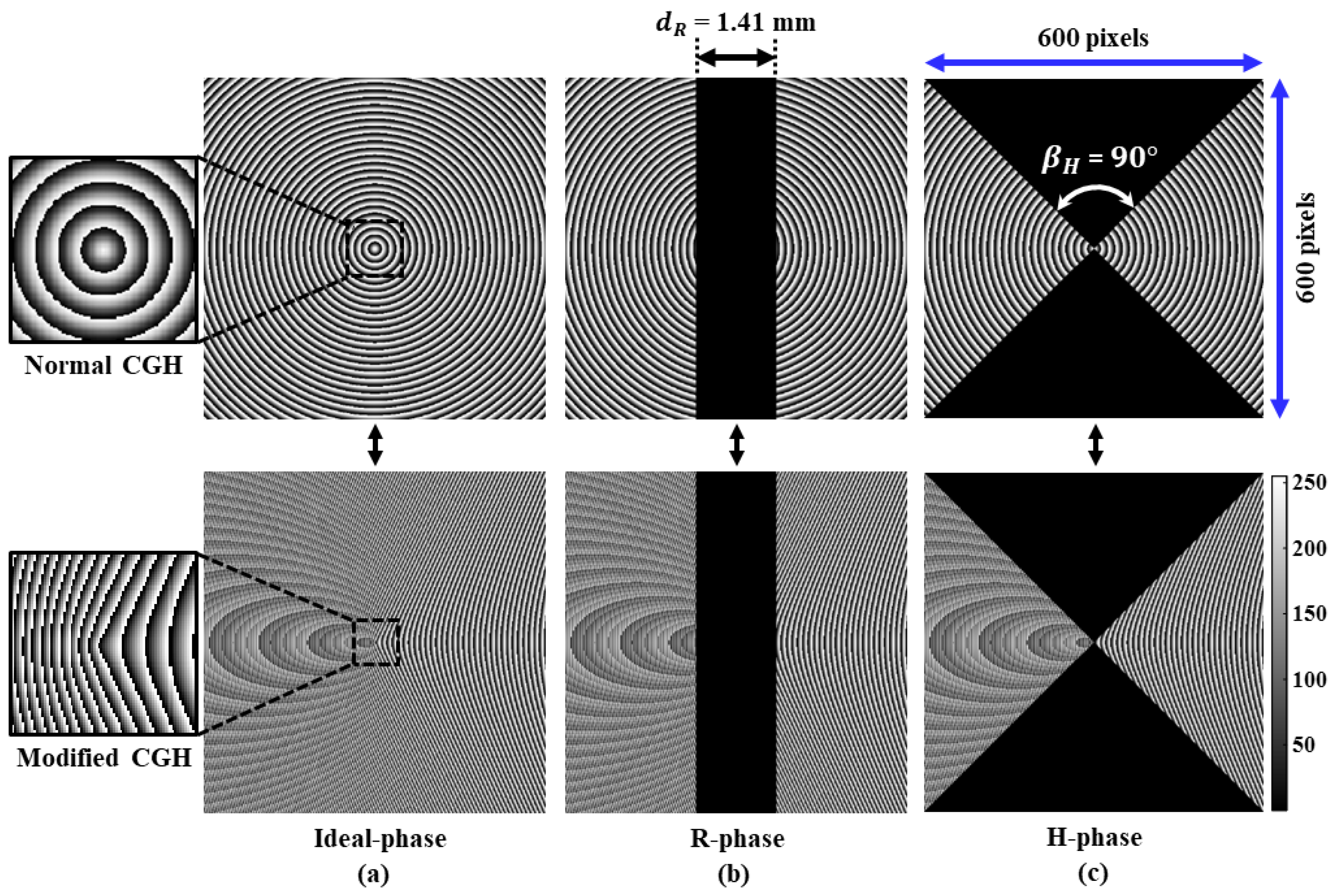
) for obtaining the maximum efficiency. The experimental setup is configured in such a way that one can directly implement it during the laser processing application. Therefore, to avoid any damages and non-linear effects during the intense beam propagation through the optical elements, the CGHs are created (see Figure 8) for a thin axicon of α = 0 . 4 with n = 1.45. For characterization purposes, the energy of the input beam is kept far below the damage threshold of the LCOS-SLM device. LCOS-SLM modulates the phase of the incident collimated laser beam according to the CGH displayed on its screen and thus spatially shapes the input beam to produce the elliptical BG beam upon reflection. The incident beam size ( ω 0 2.5 mm at 1/ e 2 ) is kept smaller than the window size of the LCOS-SLM screen (792 × 600 pixels, pixel-pitch = 20 μ m) to avoid any undesired aperture effect in the generated beam.
The illumination on the pixelated LCOS-SLM screen diffracts light mainly into three components (0-th order undiffracted, and +1, −1 order diffracted beams). The superposition of this 0-th order component (basically noise) with the other diffracted orders strongly modulates the intensity profile of the generated beam along the propagation direction after the LCOS-SLM, as shown in the inset-A (typical image obtained in simulation) of Figure 7. Therefore, it is essential to spatially separate and block the undesired diffraction orders to make the beam oscillation free, and it is accomplished by adding a blazed grating phase to the initially calculated CGH using the mathematical expression given by [29,34]:
Φ C G H ( x , y ) = ϕ F ( x , y ) × m o d ϕ a ( x , y ) + 2 π ( Γ x x + Γ y y ) , 2 π
Here, ϕ F ( x , y ) is the phase expression of the in-phase filters imposed on the axicon phase ϕ a ( x , y ) , and Γ x 9 lines/mm and Γ y = 0 are the spatial frequencies of the blazed grating along x and y axes, respectively. The calculated CGHs are wrapped over [0–2 π ] using the function ‘mod’, and hence converted into the gray-scale before displaying on the LCOS-SLM screen, as shown in Figure 8.
The modified CGHs spatially separate the diffracted components at the FP of a PCL ( L 1 : f 1 = 1 m), where we place an aperture mounted on a x y z -transnational stage only to allow the +1 order (containing relatively higher energy) to pass through the second PCL ( L 2 : f 2 = 50 mm) of the 4f system. Note that a properly designed blazed grating can achieve above 90% diffraction efficiency in the +1 order [34,35], and with the damage threshold of around 1 mJ, the used LCOS-SLM can deliver enough energy to the sample plane to make laser-induced damage. This efficient and highly controllable beam-shaping technique produces a uniform and demagnified (by a factor of 20) version of the elliptical BG beam after the 4f system, which is hence ready for the laser-material processing, as shown in the inset-B (typical image obtained in simulation) of Figure 7. The generated elliptical micro-BG beam is finally characterized using a high-resolution 4f imaging system mounted on a micro-precision x y z -transnational stage by recording several transverse images along the optical axis. The imaging system consists of a long working distance microscope objective with a high numerical aperture (50X/NA 0.42, Mitutoyo), a tube lens ( L 3 : f 3 = 40 mm), and a calibrated CCD camera having linear response.

5. Results and Discussions

Experimental investigations and characterization of the ultrafast micro-elliptical BG beams are carried out (see Figure 9) using the computed CGHs of different types and the optical scheme (Figure 7) as discussed before. The experimentally obtained beam profiles are compared with the simulation to verify the performance of our beam-shaping technique using the developed numerical model (see Section 3.1) based on the FTFM method [32,33]. Several spatial filtering techniques are noted for making uniform on-axis Bessel intensity profiles [24,36,37], which are limited by energy loss and uncontrolled beam parameters. To solely realize a uniform axial intensity distribution, we implement a beam-shaping technique by displaying the modified CGHs on the LCOS-SLM screen, as shown in Figure 8. It efficiently eliminates any undesired optical noises at the FP based on the controlled phase-grating parameters and thus makes the resulting demagnified beams completely uniform which would otherwise have oscillatory behavior [19].
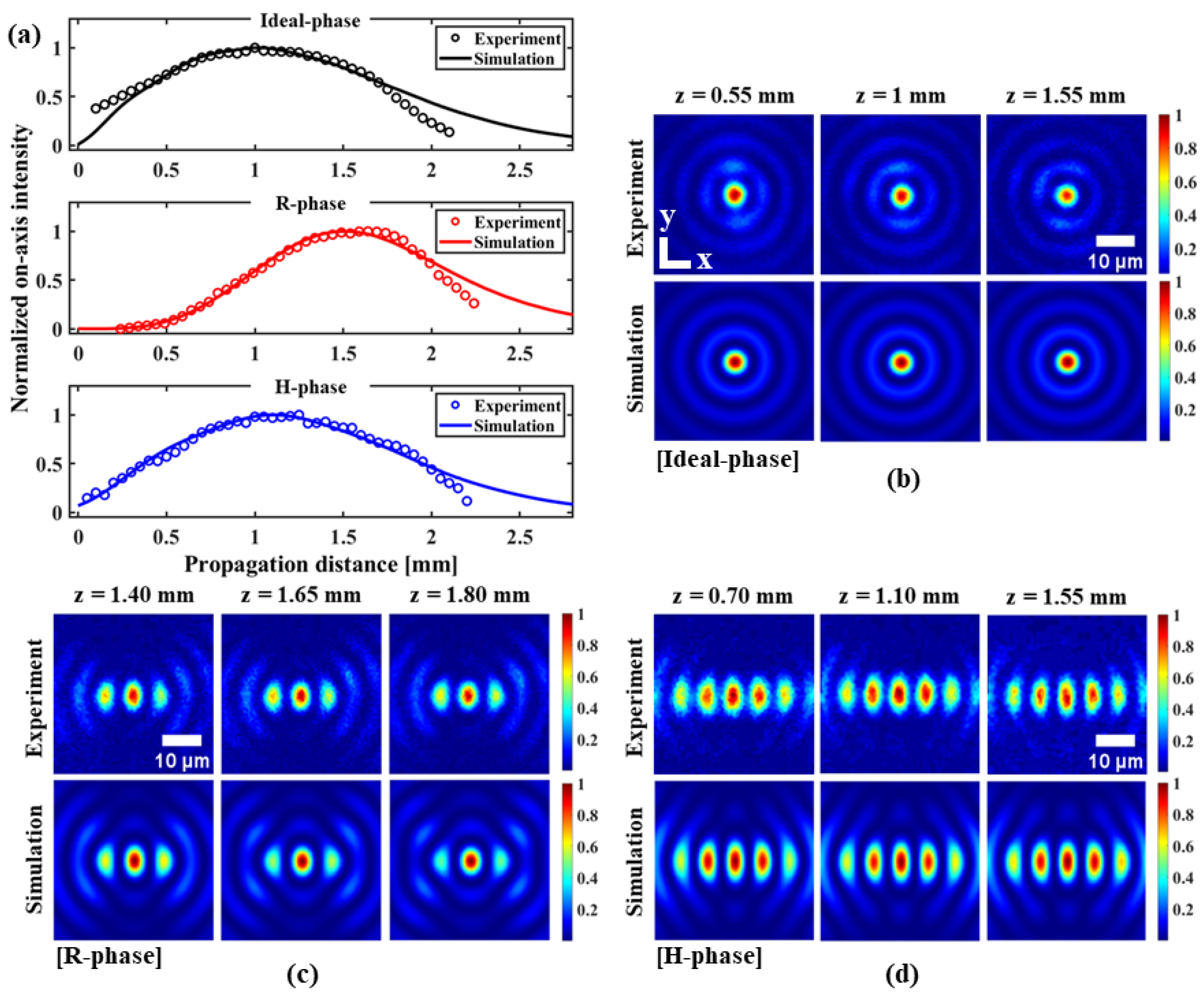
Figure 9a shows the uniform on-axis intensity distributions of the symmetric and elliptical BG beams generated by the modified CGHs of ideal-phase, R-phase (with d R = 1.41 mm) and H-phase (with β H = 90 ), respectively. The experimentally measured on-axis profiles are fitted with the simulated profiles which show the closest match and clearly indicate the high uniformity of the generated beams. The on-axis profile with ideal-phase shows a non-diffractive Bessel length of z m a x = 1.58 mm (according to fit). However, a relative reduction of Bessel length ( z m a x = 1.27 mm) is observed in the case of R-phase, while the H-phase maintains the Bessel length of z m a x = 1.53 mm very close to that of ideal-phase irrespective of the in-phase filter dimensions. Furthermore, a significant shift of the on-axis profile is observed along the propagation direction (z) in the case of R-phase, whereas the position and shape of the on-axis profile remain conserved for H-phase while comparing with the ideal-phase. This observation surely highlights the advantage of using the H-phase in terms of maintaining the ideal nature of the on-axis profile.
Figure 9b–d shows images of the measured beam profiles (in xy plane) of the generated beams at different propagation distances. Interestingly, the experimentally measured beam profiles are observed to be in excellent agreement with the simulation. This definitively confirms the accuracy and high controllability of the LCOS-SLM-based beam-shaping technique for the generation of elliptical BG beams. The above-mentioned figures confirm that both R-phase and H-phase (oriented along y axis) produce elliptical BG beams. It is observed that the generated beams contain elliptical central cores surrounded by the evolution of multi-channel elliptical cores (along x axis), the asymmetry of which is entirely defined by the spatial dimensions of the in-phase filters (oriented along y axis) as also numerically analyzed in Figure 5 and Figure 6, respectively, (evolution of multi-channel cores also increases with filter dimensions).
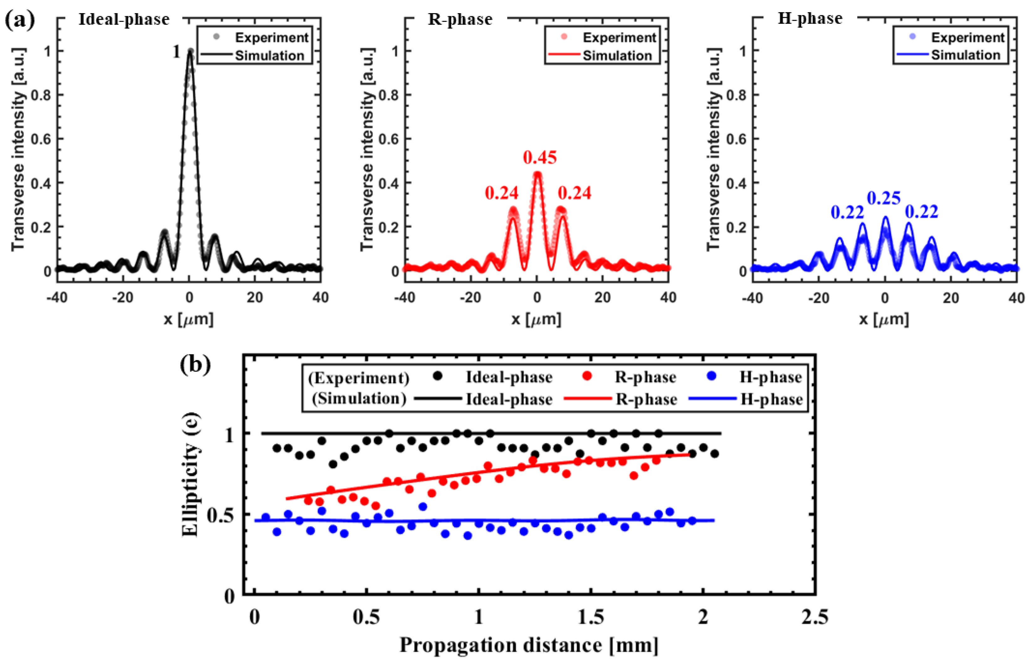
Figure 10a shows the transverse intensity profiles at the corresponding peak on-axis intensity positions (see Figure 9a) for ideal-, R- and H-phase, respectively. The profiles are normalized with respect to the peak intensity value as obtained with the ideal-phase for intensity comparison. It is observed that the implementation of different asymmetric phases lowers the peak intensity level by a factor of ∼0.55 for R-phase and ∼0.75 for H-phase as compared to the ideal-phase. This intensity reduction is analogous to the distributed intensity from the central core to the side cores of the generated asymmetric beams for the in-phase filters of specific dimensions (in this case, d R = 1.41 mm for R-phase and β H = 90 for H-phase). Now, it is interesting to point out that the R-phase exhibits higher intensity contrast (∼0.21) between the central and ±1 order cores as compared to the H-phase. The relatively low intensity contrast (∼0.03) would make H-phase advantageous to use in particular application such as high-aspect-ratio multi-nano-channels, with the access of enough supplied energy (below the damage threshold of LCOS-SLM).
Figure 10b shows the variation of central core ellipticity of the generated asymmetric beams as a function of z for different conical phases. It is observed that the ellipticity values as estimated in the simulation is fitting well with the experimentally obtained values. The ellipticity (e) is calculated as a ratio of FWHM of the central core along x and y axes. We obtain the e values (at the peak on-axis positions) of ∼0.96, 0.82, and 0.40 (in experiment), which is in good agreement with simulation (e = 1, 0.84, and 0.46) for the ideal-, R-, and H-phase, respectively. Interestingly, the H-phase profoundly exhibits the desired non-diffractive behavior (maintained ellipticity along propagation), which is consistent with the ideal-phase. However, for the R-phase, an abrupt increase of e value (i.e., corresponding to the decrease in overall beam ellipticity) is observed with propagation, which makes the beam pseudo-non-diffractive. This squeezing effect is mainly attributed to the modulated Bessel ring (see Section 2.1) that remains even after applying the modified CGH. A direct influence of this instability is also noted in the on-axis profile. Specifically, the leading part of the R-phase generated on-axis profile (see Figure 10a) becomes slowly varying. This behavior is in contrast to that of H-phase, which maintains its non-diffractive characteristic. The above observations clearly highlight the limitation of the R-phase and emphasize the effectiveness of using the H-phase for elliptical BG beam generation.
Furthermore, in order to solely realize the asymmetric characteristics of the elliptical BG beams generated by R- and H-phase, we numerically calculate the unwrapped phase profiles at different z values, and compare the results with the ideal-phase, as represented in Figure 11a–c.
In the case of R-phase, the effect on the phase asymmetry is clearly visible at the beginning (at z = 0.62 mm), whereas this effect smears (loss of asymmetry) with propagation due to the strong diffraction (stronger along x axis) caused by the rectangular-shaped filter of the R-phase. However, the diffraction effect caused by the triangular-shaped filter of the H-phase is compensated (phase asymmetry is maintained) along propagation by the radial wave-vector components kicking out in different directions. It clearly explains the origin of instability in the case of R-phase and also confirms the robustness of H-phase for the generation of high-quality nearly non-diffractive elliptical BG beams. The phase asymmetry ( e p ) is calculated in terms of the ellipticity of the central lobe of the phase images and represented as a function of z for different conical phases, as shown in Figure 11d. The curves (indicated by dotted lines) show similar nature (i.e., unstable and maintained phase asymmetry for R- and H-phase, respectively) as we also previously obtained in Figure 10b, which supports the above discussions.
The above results indicate that the R-phase is less efficient in maintaining the ellipticity but preserves a high-intensity peak (relative intensity of ∼0.45), while H-phase has a propagation-invariant ellipticity at the expense of shifting energy on the localized side lobes. This originates from the conical interaction of waveforms where radially different phase elements correspond to axially different propagation points, indicating the need to control diffraction at different distances from the conical element.
Finally, our study based on the advanced spatial beam-shaping technique (see Figure 8) uses the highly controlled asymmetric CGHs which provide a uniform micro-elliptical BG generation (avoids unwanted energy loss in terms of not blocking the Fourier Bessel ring) with precise controllability. The obtained highly elliptical and nearly non-diffractive central core along with the side multichannels of the generated asymmetric beams ensure their applicability in the ultrafast laser-material processing applications, and particularly would be an efficient choice of interest in high-speed laser-glass cutting [24,25,26], high-aspect-ratio multi-nano-channels [21], and scientific study of non-linear optics, e.g., super-continuum generation [38,39]. Nevertheless, situations may appear where the high contrast of the side lobes may be detrimental. We note that this appears to be inherently related to the tradeoff between ellipticity and central lobe intensity, being related to the reconstruction capacity of the beam.

6. Conclusions

In conclusion, we explore the controlled generation of ultrafast elliptical BG beams using a phase-only reflective type LCOS-SLM device. This study evaluates the performance of two asymmetric phases (R- and H-phase) for generating asymmetric beams. The study highlights that the R-phase is more prone to diffraction which makes the resulting beam pseudo-non-diffractive. In contrast to the R-phase, our study shows higher compatibility with the H-phase in terms of attaining the ideal nature of the on-axis profile while maintaining high central core ellipticity along propagation. An ellipticity of e 0.40 (at peak on-axis intensity position) is achieved with H-phase. These suggest that the H-phase would be a more suitable choice for generating high-quality asymmetric beams compared to the R-phase.
This study also presents a numerical model based on the FTFM method to simulate beam propagation and analyze the quality of elliptical BG beams generated using the CGHs of R- and H-phase, in comparison to the symmetric BG beams. The experimental results are found to be in excellent agreement with the simulation, which validates our theoretical interpretations. The results show that the LCOS-SLM-based beam-shaping technique is accurate and effective in generating high-quality uniform micro-elliptical BG beams with high ellipticity, making it suitable for potential ultrafast laser processing applications and other related domains. The study emphasizes the importance of using appropriate phase configurations to generate nearly non-diffractive asymmetric beams and also provides insights into the fundamental properties of such beams.

Author Contributions

N.G. developed the theoretical formalism, construct the numerical model, performed the analytical calculations and simulations, and wrote the manuscript. N.G. and R.D. contributed to the experiment. C.D. and R.S. proposed the idea and supervised the findings of this work. All authors have read and agreed to the published version of the manuscript.

Funding

The study was funded by the French National Research Agency (ANR) grant ANR-21-CE08-0005.

Data Availability Statement

Data underlying the results presented in this paper are not publicly available at this time but may be obtained from the authors upon reasonable request.

Conflicts of Interest

The authors declare no conflict of interest.

Abbreviations

The following abbreviations are used in this manuscript:
BGBessel–Gauss
CGHComputer-generated hologram
FPFourier plane
FTFMFresnel transfer function method
FWHMFull width at half maxima
LCOS-SLMLiquid crystal on silicon-based spatial light modulator

References

  1. Mcgloin, D.; Dholakia, K. Bessel beams: Diffraction in a new light. Contemp. Phys. 2005, 46, 15–28. [Google Scholar] [CrossRef]
  2. Durnin, J. Exact solutions for nondiffracting beams. I. The scalar theory. J. Opt. Soc. Am. A 1987, 4, 651–654. [Google Scholar] [CrossRef]
  3. Arnold, C.L.; Akturk, S.; Mysyrowicz, A.; Jukna, V.; Couairon, A.; Itina, T.; Stoian, R.; Xie, C.; Dudley, J.M.; Courvoisier, F.; et al. Nonlinear Bessel vortex beams for applications. J. Phys. B At. Mol. Opt. Phys. 2015, 48, 094006. [Google Scholar] [CrossRef]
  4. Duocastella, M.; Arnold, C.B. Bessel and annular beams for materials processing. Laser Photonics Rev. 2012, 6, 607–621. [Google Scholar] [CrossRef]
  5. Bhuyan, M.; Courvoisier, F.; Lacourt, P.; Jacquot, M.; Salut, R.; Furfaro, L.; Dudley, J. High aspect ratio nanochannel machining using single shot femtosecond Bessel beams. Appl. Phys. Lett. 2010, 97, 081102. [Google Scholar] [CrossRef]
  6. Chen, T.; Zhang, G.; Wang, Y.; Li, X.; Stoian, R.; Cheng, G. Reconstructing of Embedded High-Aspect-Ratio Nano-Voids Generated by Ultrafast Laser Bessel Beams. Micromachines 2020, 11, 671. [Google Scholar] [CrossRef]
  7. Matsuoka, Y.; Kizuka, Y.; Inoue, T. The characteristics of laser micro drilling using a Bessel beam. Appl. Phys. A Mater. Sci. Process. 2006, 84, 423–430. [Google Scholar] [CrossRef]
  8. He, F.; Yu, J.; Tan, Y.; Chu, W.; Zhou, C.; Cheng, Y.; Sugioka, K. Tailoring femtosecond 1.5-μm Bessel beams for manufacturing high-aspect-ratio through-silicon vias OPEN. Sci. Rep. 2017, 7, 40785. [Google Scholar] [CrossRef]
  9. Lopez, J.; Mishchik, K.; Chassagne, B.; Javaux-Leger, C.; Hönninger, C.; Mottay, E.; Kling, R. Glass cutting using ultrashort pulsed bessel beams. In Proceedings of the International Congress on Applications of Lasers & Electro-Optics 2015, Atlanta, GA, USA, 18–22 October 2015. [Google Scholar] [CrossRef]
  10. Nguyen, H.D.; Moreno, E.; Rudenko, A.; Faure, N.; Sedao, X.; Mauclair, C.; Colombier, J.P.; Stoian, R. Super-efficient drilling of metals with ultrafast non diffractive laser beams. Sci. Rep. 2022, 12, 2074. [Google Scholar] [CrossRef]
  11. McLeod, J.H. The Axicon: A New Type of Optical Element. J. Opt. Soc. Am. 1954, 44, 592–597. [Google Scholar] [CrossRef]
  12. Stoian, R.; Bhuyan, M.K.; Zhang, G.; Cheng, G.; Meyer, R.; Courvoisier, F. Erratum to: Ultrafast Bessel beams: Advanced tools for laser materials processing. Adv. Opt. Technol. 2019, 8, 535. [Google Scholar] [CrossRef]
  13. Perinchery, S.M.; Shinde, A.; Fu, C.Y.; Jeesmond Hong, X.J.; Baskaran, M.; Aung, T.; Murukeshan, V.M. High resolution iridocorneal angle imaging system by axicon lens assisted gonioscopy. Sci. Rep. 2016, 6, 30844. [Google Scholar] [CrossRef] [PubMed] [Green Version]
  14. Takanezawa, S.; Saitou, T.; Imamura, T. Wide field light-sheet microscopy with lens-axicon controlled two-photon Bessel beam illumination. Nat. Commun. 2021, 12, 2979. [Google Scholar] [CrossRef] [PubMed]
  15. Arimoto, R.; Saloma, C.; Tanaka, T.; Kawata, S. Imaging properties of axicon in a scanning optical system. Appl. Opt. 1992, 31, 6653–6657. [Google Scholar] [CrossRef] [PubMed]
  16. Bin, Z.; Zhu, L. Diffraction property of an axicon in oblique illumination. Appl. Opt. 1998, 37, 2563–2568. [Google Scholar] [CrossRef] [PubMed]
  17. Dwivedi, R.; Sharma, P.; Jaiswal, V.K.; Mehrotra, R. Axicon aberration leading to short-range nondiverging optical array and elliptical dark hollow beam. Opt. Eng. 2018, 57, 055106. [Google Scholar] [CrossRef]
  18. Kotlyar, V.V.; Kovalev, A.A.; Soifer, V.A. Asymmetric Bessel modes. Opt. Lett. 2014, 39, 2395–2398. [Google Scholar] [CrossRef]
  19. Dudutis, J.; GeČys, P.; RaČiukaitis, G. Non-ideal axicon-generated Bessel beam application for intra-volume glass modification. Opt. Express 2016, 24, 28433–28443. [Google Scholar] [CrossRef]
  20. Dwivedi, R.; Sharma, P.; Jaiswal, V.; Mehrotra, R. Elliptically squeezed axicon phase for detecting topological charge of vortex beam. Opt. Commun. 2021, 485, 126710. [Google Scholar] [CrossRef]
  21. Meyer, R.; Jacquot, M.; Giust, R.; Safioui, J.; Rapp, L.; Furfaro, L.; Lacourt, P.A.; Dudley, J.; Courvoisier, F. Single shot ultrafast laser processing of high-aspect ratio nanochannels using elliptical Bessel beams. Opt. Lett. 2017, 42, 4307–4310. [Google Scholar] [CrossRef] [Green Version]
  22. Dudutis, J.; Pipiras, J.; Schwarz, S.; Rung, S.; Hellmann, R.; Raciukaitis, G.; Gecys, P. Laser-fabricated axicons for glass dicing applications. Procedia CIRP 2020, 94, 957–961. [Google Scholar] [CrossRef]
  23. Jenne, M.; Flamm, D.; Chen, K.; Schäfer, M.; Kumkar, M.; Nolte, S. Facilitated glass separation by asymmetric Bessel-like beams. Opt. Express 2020, 28, 6552–6564. [Google Scholar] [CrossRef] [PubMed]
  24. Dudutis, J.; Mackevičiūtė, M.; Pipiras, J.; Stonys, R.; Stankevič, V.; Račiukaitis, G.; Gečys, P. Transversal and axial modulation of axicon-generated Bessel beams using amplitude and phase masks for glass processing applications. Opt. Express 2022, 30, 1860–1874. [Google Scholar] [CrossRef] [PubMed]
  25. Dudutis, J.; Stonys, R.; Račiukaitis, G.; Gečys, P. Aberration-controlled Bessel beam processing of glass. Opt. Express 2018, 26, 3627–3637. [Google Scholar] [CrossRef] [PubMed]
  26. Dudutis, J.; Stonys, R.; Račiukaitis, G.; Gečys, P. Bessel beam asymmetry control for glass dicing applications. Procedia CIRP 2018, 74, 333–338. [Google Scholar] [CrossRef]
  27. Dwivedi, R.; Sharma, P.; Jaiswal, V.; Mehrotra, R. Tunable phase of elliptical axicon for controlled spectral switching. Optik 2021, 237, 166734. [Google Scholar] [CrossRef]
  28. Chen, K.; Jenne, M.; Grossmann, D.G.; Flamm, D. Generalized axicon-based generation of nondiffracting beams. arXiv 2019, arXiv:1911.03103. [Google Scholar]
  29. Bowman, R.; D’Ambrosio, V.; Rubino, E.; Jedrkiewicz, O.; Trapani, P.; Padgett, M. Optimisation of a low cost SLM for diffraction efficiency and ghost order suppression. Eur. Phys. J. Spec. Top. 2011, 199, 149–158. [Google Scholar] [CrossRef]
  30. Akturk, S.; Arnold, C.L.; Prade, B.; Mysyrowicz, A. Generation of high quality tunable Bessel beams using a liquid-immersion axicon. Opt. Commun. 2009, 282, 3206–3209. [Google Scholar] [CrossRef] [Green Version]
  31. Tiwari, S.K.; Mishra, S.R.; Ram, S.P.; Rawat, H.S. Generation of a Bessel beam of variable spot size. Appl. Opt. 2012, 51, 3718–3725. [Google Scholar] [CrossRef]
  32. Voelz, D.G. Computational Fourier Optics: A MATLAB Tutorial; SPIE Tutorial Texts, TT89; SPIE Press: Bellingham, WA, USA, 2011. [Google Scholar]
  33. Goodman, J.W. Introduction to Fourier Optics. In Introduction to Fourier Optics, 3rd ed.; Goodman, J.W., Ed.; Roberts Co. Publ.: Englewood, CO, USA, 2005; Volume 1. [Google Scholar]
  34. Society of Photo-Optical Instrumentation Engineers (SPIE). How to Shape Light with Spatial Light Modulators; SPIE Press: Bellingham, WA, USA, 2017. [Google Scholar]
  35. Swanson, G.; Lincoln Laboratory. Binary Optics Technology: The Theory and Design of Multi-Level Diffractive Optical Elements; Technical Report (Lincoln Laboratory); Massachusetts Institute of Technology, Lincoln Laboratory: Cambridge, MA, USA, 1989. [Google Scholar]
  36. Bhuyan, M.; Praveen Kumar, V.; Somayaji, M.; Colombier, J.P.; Stoian, R. 3D Nano-Fabrication Using Controlled Bessel-Glass Interaction in Ultra-fast Modes. J. Laser Micro Nanoeng. 2017, 12, 274–280. [Google Scholar] [CrossRef]
  37. Stsepuro, N.; Nosov, P.; Galkin, M.; Krasin, G.; Kovalev, M.; Kudryashov, S. Generating Bessel-Gaussian Beams with Controlled Axial Intensity Distribution. Appl. Sci. 2020, 10, 7911. [Google Scholar] [CrossRef]
  38. Majus, D.; Dubietis, A. Statistical properties of ultrafast supercontinuum generated by femtosecond Gaussian and Bessel beams: A comparative study. J. Opt. Soc. Am. B 2013, 30, 994–999. [Google Scholar] [CrossRef]
  39. Wu, J.; Huo, L.; Ni, Y.; Wu, Z.; Chen, T.; Gao, S.; Li, S. Supercontinuum Induced by Filamentation of Bessel-Gaussian and Laguerre-Gaussian Beams in Water. Appl. Sci. 2022, 12, 6005. [Google Scholar] [CrossRef]
Figure 1. (a) Conceptual conical phase structures (ideal-phase, R- and H-phase). (b) Wave vector components describing the propagation dynamics after the conical phase plane.
Photonics 10 00651 g001
Figure 2. Schematic ray diagram of the elliptical BG beam formation by the asymmetric phases (R-phase and H-phase) (left). Typical nature of the angular spectrum (traced along x) showing strong modulation in the Bessel ring for R-phase (responsible for pseudo-non-diffractive elliptical BG beam generation), whereas both R- and H-phase produce central optical noises (right). FP: Fourier plane, PCL: plano-convex lens.
Photonics 10 00651 g002
Figure 3. Schematic diagram of the algorithm for simulating BG beam propagation through a 4f system. The final beam is a demagnified version of the initially generated BG beam. F F T : Fast Fourier transform, f 1 , f 2 : focal lengths associated to the lens transformations in the 4f system.
Photonics 10 00651 g003
Figure 4. Numerically obtained intensity profiles of the symmetric Bessel–Gauss beam after 4f propagation. (a) Longitudinal intensity maps in the xz and yz planes; (b) On-axis intensity distribution and its theoretical comparison; (c) Transverse (xy plane) intensity profiles at propagation distance z = 0.17 mm, z = 0.34 mm (peak on-axis intensity), and z = 0.68 mm showing the non-diffractive central core of the generated beam along the propagation direction.
Photonics 10 00651 g004
Figure 5. Numerical analysis of asymmetric R-phase in the generation of elliptical BG beam (after 4f propagation). (a) The on-axis intensity profiles for different in-phase filter sizes ( d R = 0.31 mm, 0.81 mm, and 1.41 mm, respectively) showing a successive reduction of Bessel lengths. (b) The longitudinal intensity maps in xz and yz planes for d R = 1.41 mm. (c) Images of the beam profiles (right), and their corresponding intensity distributions (along x and y) (left), at distances of the peak on-axis intensities for different d R values. An increase of d R leads to the increment of the central core ellipticity of the beam.
Photonics 10 00651 g005
Figure 6. Numerical analysis of the asymmetric H-phase in the generation of elliptical BG beam (after 4f propagation). (a) The non-shifted on-axis intensity profiles showing the maintained Bessel lengths for different in-phase filter dimensions ( β H = 28.07 , 61.93 , and 90 , respectively). (b) The longitudinal intensity maps in xz and yz planes for β H = 90 . (c) Images of the beam profiles (bottom), and their corresponding intensity distributions (along x and y) at the peak on-axis intensity position (at z = 0.45 mm for all β H ) (top). An increase in β H leads to the increment of the central core ellipticity of the beam.
Photonics 10 00651 g006
Figure 7. The experimental setup for LCOS-SLM-based controlled generation of uniform ultrafast micro-elliptical BG beams. The configuration is shown with the condition when CGH is OFF (not displayed). The typical longitudinal intensity maps of the generated beam after the LCOS-SLM device (oscillated profile) and 4f system (uniform profile by applying beam-shaping) are shown in the inset-A and inset-B, respectively, when CGH is ON (displayed). The subscripts M, L, and I represent mirrors, lenses, and iris, respectively. The arrow indicates the direction of laser propagation (k).
Photonics 10 00651 g007
Figure 8. Phase-only computer-generated holograms (CGHs) and their modified versions (addition of blazed grating phase) computed for (a) Ideal-phase, (b) Asymmetric R-phase, and (c) Asymmetric H-phase, respectively, for shaping a Gaussian laser beam to produce uniform non-diffractive symmetric and elliptical BG beams. The dimension of each CGH is 600 × 600 pixels (pixel-pitch = 20 μ m). The insets represent the zoomed central view of the CGHs.
Photonics 10 00651 g008
Figure 9. Controlled and precise generation of micro-elliptical Bessel–Gauss beams using the modified CGHs of different types (for input laser beam size ω 0 2.5 mm measured at 1/ e 2 ). (a) Comparison of simulated and experimentally obtained (after 4f system) uniform on-axis intensity distributions for ideal-phase, R-phase with d R = 1.41 mm, and H-phase with β H = 90 , respectively. The comparison of experimentally obtained and simulated beam profile images (in xy plane) at different propagation distances (z) for—(b) Ideal-phase, (c) R-phase, and (d) H-phase, respectively. The experimental results are in good agreement with the simulation.
Photonics 10 00651 g009
Figure 10. (a) Comparison of simulated and experimentally obtained transverse intensity profiles at the corresponding peak on-axis intensity positions for ideal-, R- and H-phase, respectively, showing the intensity contrast between the multi-cores (profiles are measured at the same input energy level). (b) Comparison of simulated and experimentally obtained central core ellipticity (e) as a function of propagation distance (z). The parameter e is calculated as the ratio of FWHM of the central core along the x and y axes.
Photonics 10 00651 g010
Figure 11. Unwrapped phase profiles (in xy plane) calculated at different propagation distances (z) for—(a) Ideal-phase, (b) R-phase, and (c) H-phase, respectively. (d) Variation of phase ellipticity e p (calculated in terms of the ellipticity of the central lobe of the phase images) as a function of z. Dotted lines are made to guide the eye.
Photonics 10 00651 g011
Disclaimer/Publisher’s Note: The statements, opinions and data contained in all publications are solely those of the individual author(s) and contributor(s) and not of MDPI and/or the editor(s). MDPI and/or the editor(s) disclaim responsibility for any injury to people or property resulting from any ideas, methods, instructions or products referred to in the content.

