Abstract
Free-space optical (FSO) communications can offer high-capacity transmission owing to the properties of the laser beams. However, performance degradation caused by atmospheric turbulence is an urgent issue. Recently, the application of polar codes, which can provide capacity-achieving error-correcting performance with low computational cost for decoding, to FSO communications has been studied. However, long-distance and real-field experiments have not been conducted in these studies. To the best of our knowledge, this study is the first to present the experimental results of polar-coded transmission over 7.8-km FSO links. Using experimental data, we investigated the performance of polar codes over atmospheric channels, including their superiority to regular low-density parity-check codes. We expect that our results will offer a path toward the application of polar codes in high-speed optical communication networks including satellites.
1. Introduction
Free-space optical (FSO) communications are expected to satisfy the continually increasing demand for high-capacity wireless communication [1] owing to features such as a wide bandwidth in an unregulated spectrum, ultra-low inter-channel interference, and power-efficient transmission. In addition, implemented in satellites, FSO communications can expand the coverage of high-speed communications to the sea and sky, where optical fiber implementation is difficult [2]. However, a laser beam propagating in the atmosphere is influenced by atmospheric turbulence, which causes random fluctuations in the received power and thus degrades communication performance.
Error-correcting codes, used in radio-frequency wireless and fiber-based optical communications, remain an effective means to address this problem even in FSO communications. The application of conventional error-correcting codes, such as the Reed–Solomon [3], low-density parity check (LDPC) [4], and turbo [5] codes for FSO communications has been investigated through numerical simulation and experiments [6,7,8]. In parallel, discussions on the standardization of error-correcting codes in satellite-to-ground FSO communications have been promoted by the Consultative Committee for Space Data Systems (CCSDS) [9].
In recent years, the application of polar codes [10] to optical wireless communication has also been investigated. Polar codes are known as capacity-achieving codes, as with LDPC codes. Moreover, the computational costs for decoding polar codes are lower than those for LDPC codes. Recently, polar codes with successive cancellation list decoding (SCLD) [11] concatenated by cyclic redundancy check (CRC) codes, that is, polar codes with CRC-aided SCLD (CA-SCLD), can achieve a higher error-correcting performance than LDPC codes in the short-code-length regime. Refs. [12,13] experimentally revealed the superiority of polar codes over LDPC codes in terms of ultraviolet and visible light communication, respectively.
The performance of polar-coded transmission over FSO communications has also been studied numerically [14] and experimentally [15]. In particular, Ref. [15] performed a CA-SCLD polar-coded transmission experiment in a laboratory environment, and demonstrated that CA-SCLD polar code has an acceptable error-correcting performance, even over atmospheric channels. However, the communication path of the experiment was 7 m, and the fading was simulated using a hot-air heater. Therefore, the experiment addressed only a limited case with weaker turbulence. Because in a real-field environment, the degree of atmospheric turbulence varies over a wider range and the transmission distance can span from a hundred meters to several kilometers, a performance investigation in a real-field environment is highly desirable.
In this study, we report a real-field CA-SCLD polar code transmission experiment over a 7.8-km terrestrial FSO link in urban Tokyo. To the best of our knowledge, polar code transmission experiments across such extensive atmospheric paths have not been reported yet. Based on the experimental data, we demonstrate the effectiveness of equalization and block interleaving, techniques used to mitigate atmospheric effects, over a real-field long-distance FSO link. We also compared the experimental results with computational simulations that indicated the decoding performance degradation by the real-field effect. In addition, we performed a CA-SCLD benchmark test for some types of LDPC code. These results are beneficial for designing high-performance error-correcting codes for emerging non-terrestrial networks (NTN) to aid the consideration of an increase in transmission speed using the FSO link.
The results of this study partly appeared in [16] and [17]. In [16], the initial experimental results of polar code transmission were reported. However, the transmission performance could not be improved because channel equalization was not used. In [17], although the application of channel equalization improved the characteristics, the reasons that led to this improvement were not sufficiently considered. In this paper, we newly add an analysis of experimental results and a discussion to reinforce the insights deduced from the experiment. The contributions of this study are as follows:
- -
- Long-distance transmission of polar and LDPC codes over a 7.8-km terrestrial FSO link, demonstrating that the characteristics, especially block error performance, of polar codes are better than those of the regular LDPC codes;
- -
- Investigating factors that cause differences in the characteristics of polar and LDPC codes in FSO communications;
- -
- Comparing the performance of LDPC codes used in the recent standardization of the fifth-generation mobile communications system (5G) numerically, and clarifying the effectiveness of polar code transmission.
2. CA-SCLD Polar-Coded FSO Transmission System
In this section, we explain the CA-SCLD polar-coded FSO transmission system [11], the block diagram of which is displayed in Figure 1. The sender prepares a -bit message sequence, and inputs it into the CRC encoder. The CRC encoder adds -bit CRC parity to and inputs the resulting -bit sequence into a polar encoder. The polar encoder computes the location of the frozen bits (i.e., the bits with a high probability of causing an error at the receiver side) in and inserts bit “0” to the corresponding locations, which results in an -bit information sequence . We assume that with an integer . The polar encoder further transforms into the polar codeword as follows:
where is a generator matrix defined as follows:
with a unit matrix of order , the Kronecker product , and a permutation matrix that reorders the vector elements into even- and odd-index parts.

Figure 1.
Block diagram of CA-SCLD polar-coded FSO transmission system.
The sender transmits the codeword over the atmospheric channel by modulating the laser source with an on–off keying (OOK) scheme, where the laser source turns “on” for bit and turns “off” for . We assume that the inter-symbol interference induced by the atmospheric effect is negligible as in real FSO channels because of strong beam directivity. It is also assumed that the thermal noise at the receiver’s detector follows a Gaussian distribution. Therefore, the received symbol output from the channel is given as follows:
where is the channel coefficient and is the zero-mean Gaussian white noise with a variance of .
At the receiver side, soft-decision decoding [18] is performed. The SCLD decoder calculates the initial log-likelihood ratio (LLR) for each received symbol as follows:
From this initial LLR, the SCLD decoder iteratively calculates the LLR as follows:
and determines the estimation of information bit as follows:
in ascending order of the index . If is a frozen bit, immediately. Finally, the SCLD decoder outputs a list of candidates in terms of the path metrics. This list is input into the CRC decoder, and the candidate sequence passing the CRC check is finally outputted as the decoded sequence .
Before calculating , we employ a process called channel equalization. Channel gain of the atmospheric channel varies temporally. Further, in the OOK scheme, influences only the on-signal (i.e., ), as opposed to the phase modulation schemes. These effects cause asymmetry in the probability distribution of the received symbol and the LLR distribution, resulting in degradation of the error-correcting performance. Channel equalization is used to compensate for this degradation. In channel equalization, we estimate from temporally varying received sequences or channel state information (CSI).
Figure 2 displays the probability density functions of the LLR in OOK, which are numerically simulated for the cases with equalization (green line) and without equalization (blue line). These distributions have two peaks, corresponding to (left) and 1 (right). The distribution without equalization was asymmetric, and the peak for is significantly greater than that for . This asymmetry causes a misestimation of information bit . Conversely, the distribution with equalization is symmetric at LLR = 0, indicating that channel equalization significantly improves error-correcting performance.
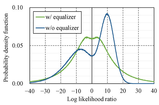
Figure 2.
Distribution of LLR for OOK scheme with and without channel equalizer. In the simulation, the signal-to-noise ratio (SNR) = 10.0 dB and the intensity variation follows a gamma–gamma distribution with scintillation index of 0.2. For the distribution without equalization, we set for all bits.
3. Experimental Setup
In this section, we describe the setup of the transmission experiment.
3.1. Tokyo FSO Testbed
The transmission experiment was conducted over an FSO communication testbed, called the Tokyo FSO testbed. As indicated in Figure 3, this testbed connects the transmission system at the University of Electro-Communications (UEC) and the receiving system at the National Institute of Information and Communications Technology (NICT). The link distance is approximately 7.8 km.
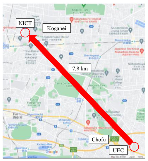
Figure 3.
Map of Tokyo FSO testbed (©2020 Google).
The transmission system at the UEC site was located in an all-weather dome-shaped facility. The light source was a direct modulation laser with a central wavelength of 1550 nm and the modulation scheme was OOK with a transmission rate of 10 MHz. Here, our goal is a high-speed FSO; however, because of the limitations of the experimental system, a 10 MHz transmission rate is used as the first step. The transmission data were input to the laser source from an arbitrary waveform generator. The modulated optical signal from the source was amplified with a fiber amplifier and coupled to a fiber collimator that expanded the laser beam to a diameter of approximately 5.5 mm.
The receiver system at the NICT site was located near the window of the building. The laser beam propagating over the 7.8 km FSO link and diverging to 8 m in full width at half maximum (FWHM) was collected using a Cassegrain-type telescope with a diameter of 100 mm and a focal length of 800 mm. The optical intensity was measured using a PIN photodiode detector and then recorded using an oscilloscope at a sampling rate of 50 MHz.
A more detailed explanation of the Tokyo FSO testbed is available in our previous studies [17,19,20,21,22].
3.2. Error-Correcting Codes
In the field experiment, we compared the error-correcting performance of the CA-SCLD polar code to that of polar code with normal (i.e., without CRC code check) SCLD decoding and regular LDPC codes. Table 1 summarizes the parameters of these codes. We set the code length to 2048 and the code rate to 0.5. We set and as the standard parameters with sufficient decoding performance [11,23,24].

Table 1.
Parameters of error-correcting codes used in the experiment.
In the polar codes, the Monte Carlo method for the AWGN channel is used to select the frozen bits [25], and those frozen bit tables are assumed to be shared between the transmitter and receiver in advance. It is empirically demonstrated that frozen bit tables for AWGN channels are also effective in fading environments, including FSO channels with strong turbulence; however, the optimization of such frozen bit tables for FSO channels remains for future study. In the LDPC code, the parity check matrix was generated based on Gallager’s semi-random construction method and the sum-product decoding algorithm was used [4].
In Table 2, we compare the computational cost of decoding these codes in terms of theoretical value and execution time. Theoretical values are calculated based on the formulas in Table 3. Table 2 illustrates the tradeoff relation between the computational cost and error-correcting performance. Owing to the employment of CRC, CA-SCLD polar code can achieve higher error-correcting performance than normal SCLD one, whereas the latter has a lower computational cost than the former. In addition, the error-correcting performance of CA-SCLD polar code is superior to that of regular LDPC code at a short code length [25] and the computational cost of the LDPC code is 35% greater than that of the polar code with CA-SCLD.

Table 2.
Computational cost of error-correcting codes used in the experiment.

Table 3.
Formulas for computational cost of error-correcting codes.
The execution time was measured using our decoding program. Our program is written in C and runs on our Linux workstation equipped with an Intel Core i9-11900K processor clocked at 3.50 GHz. The values listed in Table 2 are the averages of 100 codeword trials with the configuration listed in Table 1 with the AWGN channel having Eb/N0 = 2 dB. The relationship between these measured execution times approximately follows that of the theoretical values, corroborating the superiority of the CA-SCLD polar code. Here, the relatively long LDPC transmission execution time was due to the program not being particularly well-optimized.
3.3. Data Frame Format
Figure 4 shows a schematic diagram of our data frame format used in the transmission experiment. We designed this format to realize: (1) CSI collection for channel equalization; (2) comparison of three error correction codes under similar conditions; and (3) timing synchronization.
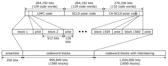
Figure 4.
Data frame format for transmission experiment.
For the information data to be transmitted, we employed the “Lena” image with a size of 131,504 bits. For the CA-SCLD polar code, we divided this image into 132 blocks with a size of 1000 bits. The last 132-th block was padded with “0” bits so that its size became 1000 bits. After adding the 24-bit CRC code, the 1024-bit blocks were encoded into 2048-bit codewords and concatenated into a 270,336-bit sequence. Similarly, for SCLD polar code and regular LDPC code, we divided the Lena image into 129 blocks of size 1024 bits. After zero-bit padding to the last block, these 1024-bit blocks were encoded into 2048-bit codewords and concatenated into a 264,192-bit sequence. We concatenated the 264,192-bit sequences for regular LDPC code and SCLD polar code and the 270,336-bit sequence for CA-SCLD polar code.
Subsequently, we divided this sequence into 1560 blocks (516 blocks for regular LDPC code and SCLD polar code, and 528 blocks for CA-SCLD polar code) with a size of 512 bits. We added a 128-bit pilot sequence, which was an iterative “01” pattern, at the end of each 512-bit sequence. CSI was estimated by averaging the received optical power for “on” symbols in the pilot. We decided on the length of pilot sequence with careful consideration: When the pilot sequence becomes longer, the precision of the CSI estimation becomes greater, whereas the transmission rate decreases. In the CCSDS standard, a series of 16 to 192 bits is typically used for synchronization [30,31]. Further, the tail sequence for LDPC codes in [30] is 128 bits. Therefore, 128 bits are used in this study.
Additionally, we constructed another sequence to investigate the effects of block interleaving. In this experiment, we adopted block interleaving at a depth of ten. We added an ancillary codeword consisting of iterative “01” patterns such that the number of code words for each error-correcting code was a multiple of ten.
Finally, we added a 256-bit preamble for synchronization at the beginning of the sequence. Thus, the frame length is 2,022,656 bits.
4. Experimental Results
In this section, we present the results of the transmission experiments. We conducted an FSO transmission campaign from 29 January 2020, at 18:00 JST, to 31 January 2020, at 13:00 JST. We transmitted a single 2,022,656-bit frame every ten minutes. During the campaign, we adjusted the transmission power to investigate the performance as a function of signal-to-noise ratio (SNR) at the receiver side. The total number of transmitted frames differed with the SNR on the receiver side. For example, 2000, 5800, and 240 frames were transmitted at 0, 10, and 24 dB, respectively.
4.1. Lena Image
Figure 5 shows a typical example of a decoded Lena image for each error-correcting code. This figure shows the characteristics of the error correction performance of these codes. As expected from the fading nature of the FSO links, burst errors occurred in these figures. However, the distribution of these errors was clearly different for these codes.

Figure 5.
Decoding result of Lena image at SNR = 6.0 dB. Note that each pixel of the Lenna image has three values for red, green, and blue (RGB).
The erroneous areas of polar codes seem completely random and no longer hold any information about the original image, whereas we can identify the original image from the decoded image to a certain extent in regular LDPC code. This is because of the property of the SCLD algorithm wherein bit errors are scattered over the codeword. Furthermore, errors are densely accumulated in polar codes, whereas they are sparsely distributed in regular LDPC code. This implies that residual error is more likely in regular LDPC code than in polar codes because the decoding of regular LDPC code is sensitive to imperfections in the CSI estimation. We further discuss the properties of the decoding algorithms for these codes in Section 5.
4.2. Error-correcting Performance
Figure 6a,b displays the bit error rate (BER) and block error rate (BLER) of the experimental data as functions of the average SNR at the receiver. For the cases without channel equalization, we subtracted the received voltage by 1/2 of the average when “on” was transmitted to the pilot symbol to mitigate the degradation due to the asymmetry of the LLR distribution [17].
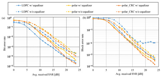
Figure 6.
(a) BER and (b) BLER of experimental data. The solid and dotted lines are for the cases with and without channel equalization, respectively.
Figure 6 demonstrates that the curves with channel equalization (solid lines) clearly surpass those without equalization (dotted lines) for both BER and BLER. The BER gain of channel equalization was approximately 4 dB with SNR = 20 dB. In addition, the error floor in the LDPC BLER, which occurs due to residual bit error generated by the sum-product algorithm, disappeared when channel equalization was applied. These observations indicate that channel equalization significantly improves the error correction performance of the polar and LDPC codes. Next, we investigate the BER and BLER performances with channel equalization.
As shown in Figure 6a, the relationship of BER performance between the three error-correcting codes is different in the lower and higher SNR regions. In the lower SNR region, the BER performance of regular LDPC was better than that of the polar codes, and the curves of the polar codes overlapped. This behavior can be due to the error-scattering property of SCLD decoding, as discussed in Section 4.1. As the SNR increases, the curve of the regular LDPC code becomes gentler and approaches that of the polar codes. The curves of the regular LDPC and CA-SCLD polar codes cross at an SNR of 19.5 dB. This is because of the residual error of sum-product decoding. Simultaneously, the gap between the two polar codes widens with an increase in SNR, indicating the efficacy of the CRC code. Its function, selecting the correct codeword from the list of potential candidates, effectively eliminates the residual error bits. This function does not work effectively in the lower SNR region because the CRC itself does not have an error-correcting ability.
BLER performance is slightly different from that of BER, as shown in Figure 6b. The curves of the polar codes are lower than those of the regular LDPC codes, which are irrelevant to SNR. This behavior indicates higher BLER performance for polar codes. The state-of-the-art standardization for modern communication systems (e.g., ground cellar systems, satellite communication systems, etc.) encourages the adoption of the packet transmission scheme with a sufficient SNR link-budget margin. We observed that polar codes were more beneficial to these systems than regular LDPC codes based on real-field transmission data.
4.3. Effect of Interleaving
In Figure 7, we show the BLER performance of three error-correcting codes without block interleaving (solid lines) and with block interleaving (dashed lines). The result demonstrates that block interleaving improves the performance because the interleaver spreads burst errors and improves the LLR quality in the decoding process.
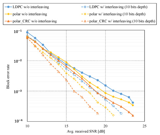
Figure 7.
BLER performance with block interleaving (dashed lines) and without block interleaving (solid lines). The solid lines are the same ones shown in Figure 6b.
4.4. Comparison with Numerical Results
We compared the error-correcting performance of the numerical simulation with the experimental results. In the simulation, we generated a sequence based on time-correlated gamma–gamma distribution [32] to mimic the channel coefficient. The distribution can be parametrized using the scintillation index (SI), which is given as follows:
where denotes the received power intensity included in the pilot sequence. We calculate the SI for the experimental data using Equation (7) and use it to generate the simulated sequence.
Figure 8a,b shows the BER and BLER performances for the experimental (solid lines) and the numerical simulation (dashed lines) results, respectively. In these figures, the simulation results outperform the experimental results. The real-field data contain several effects which are not necessarily originated from the atmospheric turbulences. This results in the deviation of the LLR of the experimental data from that obtained from the simulation, and, hence, the deterioration of the BER and BLER performances.
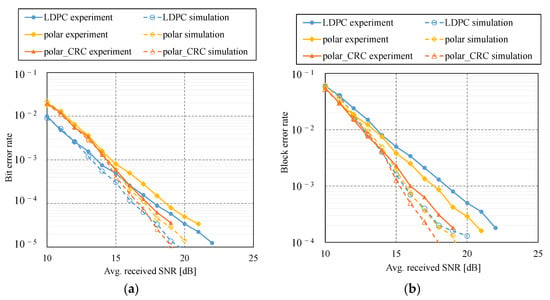
Figure 8.
Performance comparison of experiment (solid lines) and simulation results (dashed lines): (a) BER and (b) BLER. BLER performance for experimental result is the same as shown in Figure 7.
Among the three codes, the gap between the experiment and the simulation was relatively smaller for the CA-SCLD polar code compared with the others. The benefit of the CRC code is as follows: the decoding method of the other two codes depends only on the LLR. In contrast, CA-SCLD exploits the CRC code. It is independent of the LLR, and thus mitigates deterioration due to the deviation between experiment and simulation.
5. Discussion on Experimental Results
5.1. Different BER and BLER Tendency of Polar and LDPC Codes
In this subsection, we discuss the difference in the error-correcting performance of the polar and LDPC codes presented in the previous section from the viewpoint of the decoding method.
First, we provide a detailed explanation of the decoding method for the polar codes. As explained in Section 2, the SCLD algorithm calculates the LLR and estimates in ascending order of index . This algorithm is schematically represented in Figure 9. For code length , this graph has layers of nodes indexed by . The adjacent layers are connected by edges specified by the permutation matrix . The initial LLR is input into the corresponding -th node of the rightmost layer (). The LLR at each layer is then iteratively computed based on the LLRs in the right layer. Specifically, from the pair of LLRs, and for the -th layer and an odd index , LLRs and are calculated as follows:
where denotes an estimation of the information bit at the -th layer calculated from the estimations previously determined, and the functions and are defined as follows, respectively [33]:
LLRs and are sent to the next left layer over the edge. As indicated above, the LLR calculation in polar codes requires estimation of the information bit, which has previously been estimated. Therefore, if the estimation fails, the error will propagate over the code word. This explains why errors occur in the polar codes, as indicated in Figure 5.
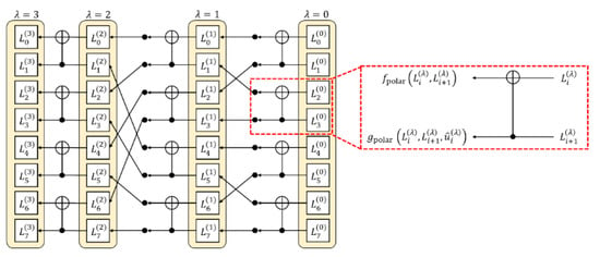
Figure 9.
Schematic diagram of SCLD algorithm for N = 23.
Second, we demonstrate that the function makes polar codes insensitive to imperfections in the CSI estimation, which is caused by the limited length of the pilot sequence. For example, we assume that we send an “all zero” codeword. In this case, should be “0” if the estimation succeeds and the LLR is likely positive. Hence, Equation (11) becomes
which is greater than that of the two inputs, and . This value is input into the function in the functions of the next layer. Recalling that the increase in the function becomes slower as increases, the functions become insensitive to small changes in the initial LLR . Therefore, polar codes become insensitive to LLR errors owing to imperfect CSI estimations.
Conversely, in the sum-product decoding of the LDPC code, a priori LLR and external are exchanged between check node and variable node at iteration . The LLR values are then updated using the following equations:
where and denote the sets of check and variable nodes connected to variable nodes and check node , respectively, and the function is given as follows:
As indicated, in LDPC codes, the LLR value is directly input to the function [34], and there is no mechanism to amplify the LLR value, such as the function in polar codes. This is why residual errors occur, as indicated in Figure 5. Hence, the BLER performance of the LDPC function is reduced by the residual errors.
5.2. Comparison with 5G LDPC Codes
We have only devoted our attention to regular LDPC code in the results presented above. However, irregular LDPC codes, which have a better performance, are the standard use in 5G new radio (NR) [35] and CCSDS [30,31]. In this subsection, we compare the characteristics of polar and irregular LDPC codes based on the numerical simulation.
We evaluated the BER characteristics of the AWGN channel versus Eb/N0 as the characteristics of channel codes are generally evaluated in a Gaussian noise channel and its relative characteristics are preserved in a fading environment. Table 4 shows the simulation parameters of the compared codes, where the basic parameters match those used for the experiments in this study (shown in Table 1). The decoding method for 5G NR LDPC was the offset min-sum algorithm with a maximum iteration number of 20. This decoding method and the iteration number are commonly used in 5G systems and it also considers the computational complexity and delay time of decoding [36,37,38]. In addition, we investigated the performance of the 5G NR LDPC code based on sum-product decoding with 50 iterations, which was the best decoding method.

Table 4.
Simulation conditions.
Figure 10 shows the BER performance of the CA-SCLD code and LDPC codes as a function of Eb/N0. The 5G NR LDPC code based on the sum-product algorithm exhibited the best performance among these codes. The relationship between CA-SCLD polar and regular LDPC codes is approximately the same in Figure 6a and Figure 8a. The former is better than the latter in the higher SNR region, and these curves cross a certain threshold. However, the threshold SNR was much lower than that shown in previous figures. This can be attributed to differences in the channel model. The AWGN channel is shown in Figure 10, whereas the gamma–gamma fading channel is shown in Figure 6 and Figure 8. Furthermore, the gamma–gamma distributions in Figure 8 are far from ideal because they were obtained through a real-field experiment. These factors deteriorate the performance of the CA-SCLD polar code more than that of the regular LDPC code; hence, the crossover point moves toward the higher-SNR region.
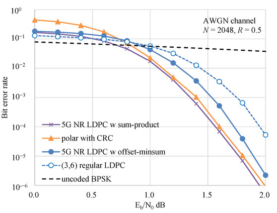
Figure 10.
Performance comparison of polar code with 5G NR LDPC code in AWGN channel.
5G NR LDPC code based on offset min-sum decoding provides an approximate 0.2 dB improvement over the (3,6) regular LDPC code at an error rate of 10−4. However, it was found that the polar code has better characteristics, which is consistent with the results of a previous study [37]. In addition, [37,39] showed that implementation of the 5G NR LDPC code is much more complex that of CA-SCLD polar code. The LDPC code used in CCSDS [30] utilizes an irregular check matrix generated using a protograph. The structure of this check matrix is similar to that of the 5G NR LDPC; therefore, the BER characteristics were considered comparable. The application of nonbinary LDPC has been discussed; however, it is not currently implemented due to the increased decoding complexity compared to the gain obtained [40]. It can be concluded that the application of polar code is effective compared to recent practical LDPC codes.
6. Conclusions
In this study, we evaluated the performance of error-correcting codes with channel estimation and equalization of polar-coded terrestrial FSO transmission over a distance of 7.8 km. The results show that the decoding performance of the codes can be improved through channel equalization. Moreover, even with channel equalization, the BLER of polar codes was superior to that of the regular LDPC codes. In addition, we compared the computational complexity of polar codes with LDPC codes and demonstrated that polar codes have a lower computational complexity than LDPC codes. Based on the results of this study, we believe that the characteristics of polar codes may be further improved by the construction of a frozen bit table for FSO communications, implementing an adaptive modification of coding rate, or the coupling of block error correcting codes, such as Reed-Solomon codes, via interleave, all of which will be considered in future studies.
Author Contributions
Conceptualization, S.F., E.O., H.T. and H.E.; methodology, S.F., H.T. and H.E.; software, S.F.; validation, E.O. and H.E.; formal analysis, S.F., E.O. and H.E.; investigation, S.F., E.O. and H.E.; resources, H.T., M.F., M.K. and R.S.; data curation, S.F. and E.O.; writing—original draft preparation, S.F.; writing—review and editing, E.O. and H.E.; visualization, S.F. and H.E.; supervision, E.O. and H.E.; project administration, E.O., M.S. and M.T. All authors have read and agreed to the published version of the manuscript.
Funding
This paper is supported by the Japan Society for the Promotion of Science (KAKENHI 17H01281), Research and Development of the Quantum Cryptography Technology for Satellite Communications (JPJ007462) in Research and Development of Information and Communications Technology (JPMI00316) of the Ministry of Internal Affairs and Communications (MIC), Japan.
Conflicts of Interest
The authors declare no conflict of interest.
References
- Khalighi, M.A.; Uysal, M. Survey on Free Space Optical Communication: A Communication Theory Perspective. IEEE Commun. Surv. Tutor. 2014, 16, 2231–2258. [Google Scholar] [CrossRef]
- Toyoshima, M. Recent trends in space laser communications for small satellites and constellations. J. Light. Technol. 2021, 39, 693–699. [Google Scholar] [CrossRef]
- Reed, I.S.; Solomon, G. Polynomial codes over certain finite fields. J. Soc. Ind. Appl. Math. 1960, 8, 300–304. [Google Scholar] [CrossRef]
- Gallager, R.G. Low-density parity-check codes. IEEE Trans. Inf. Theory 1962, 8, 21–28. [Google Scholar] [CrossRef]
- Berrou, C.; Glavieux, A.; Thitimajshima, P. Near Shannon limit error-correcting coding and decoding: Turbo-codes. In Proceedings of the ICC’93-IEEE International Conference on Communication, Geneva, Switzerland, 23–26 May 1993; Volume 2, pp. 1064–1070. [Google Scholar]
- Lee, H. A high-speed low-complexity Reed-Solomon decoder for optical communications. IEEE Trans. Circuits Syst. II Express Briefs 2005, 52, 461–465. [Google Scholar]
- Djordjevic, I.B. Adaptive Modulation and Coding for Free-Space Optical Channels. J. Opt. Commun. Netw. 2010, 2, 221–229. [Google Scholar] [CrossRef]
- Calzolari, G.P.; Chiaraluce, F.; Garello, R.; Vassallo, E. Turbo code applications on telemetry and deep space communications. In Turbo Code Applications: A Journey from a Paper to Realization; Sripimanwat, K., Ed.; Springer: Dordrecht, The Netherlands, 2005; pp. 321–344. [Google Scholar]
- CCSDS. TM Synchronization and Channel Coding-Summary of Concept and Rationale; Consultative Committee for Space Data Sys-tems (CCSDS), Informational Report, 130.1-G-3; CCSDS: Washington, DC, USA, 2020. [Google Scholar]
- Arikan, E. Channel Polarization: A Method for Constructing Capacity-Achieving Codes for Symmetric Binary-Input Memoryless Channels. IEEE Trans. Inf. Theory 2009, 55, 3051–3073. [Google Scholar] [CrossRef]
- Niu, K.; Chen, K. CRC-Aided Decoding of Polar Codes. IEEE Commun. Lett. 2012, 16, 1668–1671. [Google Scholar] [CrossRef]
- Hu, W.; Luo, Z.; Han, D.; Chen, Q.; Ai, L.; Li, Q.; Zhang, M. A scheme of ultraviolet communication system with polar channel coding. In Proceedings of the 2017 16th International Conference on Optical Communications and Networks (ICOCN), Wuzhen, China, 7–10 August 2017. [Google Scholar]
- Zhang, J.; Hu, W.; Li, X.; Zhang, M.; Han, D.; Ghassemlooy, Z. Polar coding performance for indoor LOS VLC system. In Proceedings of the 2017 IEEE/CIC International Conference on Communications in China (ICCC Workshops), Qingdao, China, 22–24 October 2017. [Google Scholar]
- Ito, K.; Okamoto, E.; Takenaka, H.; Kunimori, H.; Toyoshima, M. An adaptive coded transmission scheme utilizing frozen bits of polar code in satellite laser communications. In Proceedings of the International Conference on Space Optics—ICSO 2018, Chania, Greece, 9–12 October 2018; pp. 1–7. [Google Scholar]
- Fang, J.; Bi, M.; Xiao, S.; Yang, G.; Li, C.; Liu, L.; Zhang, Y.; Huang, T.; Hu, W. Performance investigation of the polar coded FSO communication system over turbulence channel. Appl. Opt. 2018, 57, 7378–7384. [Google Scholar] [CrossRef]
- Fujita, S.; Toyoshima, M.; Shimizu, R.; Ito, K.; Okamoto, E.; Takenaka, H.; Kunimori, H.; Endo, H.; Fujiwara, M.; Kitamura, M.; et al. Experimental evaluation of polar code transmission in terrestrial free space optics. In Proceedings of the 2019 IEEE International Conference on Space Optical Systems and Applications (ICSOS), Portland, OR, USA, 14–16 October 2019. [Google Scholar] [CrossRef]
- Fujia, S.; Okamoto, E.; Takenaka, H.; Kunimori, H.; Endo, H.; Fujiwara, M.; Shimizu, R.; Sasaki, M.; Toyoshima, M. Performance analysis of polar-code transmission experiments over 7.8-km terrestrial free-space optical link using channel equalization. In Proceedings of the International Conference on Space Optics (ICSO2020), Virtual Conference, 30 March–2 April 2021; pp. 1–9. [Google Scholar] [CrossRef]
- Balatsoukas-Stimming, A.; Parizi, M.B.; Burg, A. LLR-based successive cancellation list decoding of polar codes. IEEE Trans. Signal Process. 2015, 63, 5165–5179. [Google Scholar] [CrossRef]
- Endo, H.; Fujiwara, M.; Kitamura, M.; Ito, T.; Toyoshima, M.; Takayama, Y.; Takenaka, H.; Shimizu, R.; Laurenti, N.; Vallone, G.; et al. Free-space optical channel estimation for physical layer security. Opt. Express 2016, 24, 8940–8955. [Google Scholar] [CrossRef] [PubMed]
- Fujiwara, M.; Ito, T.; Kitamura, M.; Endo, H.; Tsuzuki, O.; Toyoshima, M.; Takenaka, H.; Takayama, Y.; Shimizu, R.; Takeoka, M.; et al. Free-space optical wiretap channel and experimental secret key agreement in 78 km terrestrial link. Opt. Express 2018, 26, 19513–19523. [Google Scholar] [CrossRef] [PubMed]
- Endo, H.; Fujiwara, M.; Kitamura, M.; Tsuzuki, O.; Ito, T.; Shimizu, R.; Takeoka, M.; Sasaki, M. Free space optical secret key agreement. Opt. Express 2018, 26, 23305–23332. [Google Scholar] [CrossRef] [PubMed]
- Endo, H.; Fujiwara, M.; Kitamura, M.; Tsuzuki, O.; Shimizu, R.; Takeoka, M.; Sasaki, M. Group key agreement over free-space optical links. OSA Contin. 2020, 3, 2525–2543. [Google Scholar] [CrossRef]
- Geiselhart, M.; Elkelesh, A.; Ebada, M.; Cammerer, S.; Brink, S.T. CRC-Aided Belief Propagation List Decoding of Polar Codes. In Proceedings of the 2020 IEEE International Symposium on Information Theory (ISIT), Los Angeles, CA, USA, 21–26 June 2020; pp. 395–400. [Google Scholar] [CrossRef]
- Zhang, Z.; Dolecek, L.; Nikolic, B.; Anantharam, V.; Wainwright, M.J. Design of LDPC decoders for improved low error rate performance: Quantization and algorithm choices. IEEE Trans. Commun. 2009, 57, 3258–3268. [Google Scholar] [CrossRef]
- Vangala, H.; Viterbo, E.; Hong, Y. A Comparative Study of Polar Code Constructions for the AWGN Channel. arXiv 2015, arXiv:1501.02473. [Google Scholar]
- Sybis, M.; Wesolowski, K.; Jayasinghe, K.; Venkatasubramanian, V.; Vukadinovic, V. Channel Coding for Ultra-Reliable Low-Latency Communication in 5G Systems. In Proceedings of the 2016 IEEE 84th Vehicular Technology Conference (VTC-Fall), Montreal, QC, Canada, 18–21 September 2016; pp. 1–5. [Google Scholar] [CrossRef]
- Song, H.; Fu, J.-C.; Zeng, S.-J.; Sha, J.; Zhang, Z.; You, X.; Zhang, C. Polar-coded forward error correction for MLC NAND flash memory. Sci. China Inf. Sci. 2018, 61, 102307. [Google Scholar] [CrossRef]
- IEEE 802.22-07/0313r0; LDPC Decoding for 802.22 Standard. IEEE: New York, NY, USA, 15–20 July 2007.
- Robertson, P.; Villebrun, E.; Hoeher, P. A comparison of optimal and sub-optimal MAP decoding algorithms operating in the log domain. In Proceedings of the IEEE International Conference on Communications ICC ‘95, Seattle, WA, USA, 18–22 June 1995; pp. 1009–1013. [Google Scholar]
- CCSDS 231.0-B-4; TC Synchronization and Channel Coding. CCSDS Secretariat National Aeronautics and Space Administration: Washington, DC, USA, 2021.
- CCSDS 131.0-B-4; TM Synchronization and Channel Coding. CCSDS Secretariat National Aeronautics and Space Administration: Washington, DC, USA, 2022.
- Bykhovsky, D. Simple Generation of Gamma, Gamma-Gamma and K Distributions with Exponential Autocorrelation Function. IEEE J. Light. Technol. 2016, 34, 2106–2110. [Google Scholar] [CrossRef]
- Tajima, S.; Takahashi, T.; Ibi, S.; Sampei, S. Iterative Decoding Based on Concatenated Belief Propagation for CRC-Aided Polar Codes. In Proceedings of the 2018 Asia-Pacific Signal and Information Processing Association Annual Summit and Conference (APSIPA ASC), Honolulu, HI, USA, 12–15 November 2018; pp. 1411–1415. [Google Scholar]
- Hagenauer, J.; Offer, E.; Papke, L. Iterative decoding of binary block and convolutional codes. IEEE Trans. Inf. Theory 1996, 42, 429–445. [Google Scholar] [CrossRef]
- GPP TS 38.212; NR; Multiplexing and Channel Coding. V15.13.0. ETSI: Sophia Antipolis, France, 2021.
- Hui, D.; Sandberg, S.; Blankenship, Y.; Andersson, M.; Grosjean, L. Channel Coding in 5G New Radio: A Tutorial Overview and Performance Comparison with 4G LTE. IEEE Veh. Technol. Mag. 2018, 13, 60–69. [Google Scholar] [CrossRef]
- Sharma, A.; Salim, M. Polar Code Appropriateness for Ultra-Reliable and Low-Latency Use Cases of 5G Systems. Int. J. Netw. Distrib. Comput. 2019, 7, 93–99. [Google Scholar] [CrossRef]
- Nguyen, T.T.B.; Tan, T.N.; Lee, H. Low-Complexity High-Throughput QC-LDPC Decoder for 5G New Radio Wireless Communication. Electronics 2021, 10, 516. [Google Scholar] [CrossRef]
- Sahin, O. A Study on Comparison of Polar and LDPC Codes above 100Gb/s Throughput Regime; IEEE 802.15 Standing Committee Terahertz; July 2019; InterDigital Europe: London, UK, 2019. [Google Scholar]
- Álvarez, Á.; Fernández, V.; Matuz, B. An Efficient NB-LDPC Decoder Architecture for Space Telecommand Links. IEEE Trans. Circuits Syst. II Express Briefs 2021, 68, 1213–1217. [Google Scholar] [CrossRef]
Disclaimer/Publisher’s Note: The statements, opinions and data contained in all publications are solely those of the individual author(s) and contributor(s) and not of MDPI and/or the editor(s). MDPI and/or the editor(s) disclaim responsibility for any injury to people or property resulting from any ideas, methods, instructions or products referred to in the content. |
© 2023 by the authors. Licensee MDPI, Basel, Switzerland. This article is an open access article distributed under the terms and conditions of the Creative Commons Attribution (CC BY) license (https://creativecommons.org/licenses/by/4.0/).