Communication

On Performance Analysis of Cooperative Horizontal and Vertical Underwater VLC Systems with Best Relay Selection

1
Institute of Technology, Nirma University, Ahmedabad 382481, Gujarat, India
2
Indian Institute of Technology Indore, Indore 453552, Madhya Pradesh, India
3
Electrical and Communication Engineering Department, College of Engineering, United Arab Emirates University, Al Ain P.O. Box 15551, United Arab Emirates
*
Authors to whom correspondence should be addressed.
Photonics 2023, 10(4), 429; https://doi.org/10.3390/photonics10040429
Submission received: 12 February 2023 / Revised: 22 March 2023 / Accepted: 6 April 2023 / Published: 11 April 2023

Abstract

:
In this paper, we consider cooperative horizontal and vertical underwater visible light communication (UWVLC) systems employing best relay selection. In the vertical UWVLC system, the source is placed at the sea surface and the destination is placed at a depth of 60 m. The link between the source and the destination is modeled as concatenated layers considering inhomogeneous environmental conditions. The underwater parameters change with depth, causing a variable refractive index, which leads to non-uniform optical turbulence. The horizontal communication link is analyzed for two different levels of turbulence at 10 m and 50 m depths. Turbulence is modeled using a log-normal distribution, whose statistical parameters depend on the temperature and salinity at different depths. We have also taken into account the path losses caused by absorption and scattering, and carried out a comprehensive performance comparison between the horizontal and the vertical UWVLC systems. Insights show that compared to horizontal links, vertical links need an extra relay in order to achieve the same level of matching performance. Moreover, it is shown that the horizontal system’s outage performance improves with depth.

1. Introduction

More than two thirds of the Earth’s surface is covered by oceans and seawater; thus, reliable underwater communication is necessary to meet the demands of present and future maritime applications [1,2,3]. Acoustic wireless communication (AWC) has been the method of choice for mariners to communicate due to its extensive transmission range. In the last decade, AWC has also been extensively explored in various applications [4,5]. AWC, however, cannot handle high data rate communication such as real-time image and video transmission because of its low data rate, high latency, and slow propagation speed (approximately 1500 m/s) [6]. Seawater has characteristics that make the blue and green wavelengths in the visible optical range between 450 and 550 nm more transparent in water and exhibit low attenuation. Hence, UWVLC is an attractive alternative to AWC for low latency and higher capacity [7]. Moreover, current trends indicate that the commercial market for underwater optical modems, which are currently available with data rates of up to 500 Mbps, will expand at a rapid rate [8,9]. However, the UWVLC system suffers from turbulence and path loss. Underwater optical turbulence occurs due to the change in the refractive index of water [10,11]. The fluctuations in the refractive index are associated with changes in the temperature, salinity, and pressure [12,13,14,15,16]. This process results in turbulence-induced fading, which causes fluctuations in the received signal’s power, consequently degrading the performance of the communication system. The underwater characteristics also change with the seasons due to changes in environmental conditions and temperature, and also with the latitude. The variation in temperature with depth according to different seasons for the Pacific Ocean is studied in [13]. Due to the absorption and dispersion of visible light photons, UWVLC experiences path loss. The transmitted signal is severely attenuated by path loss, resulting in a lower signal-to-noise ratio (SNR) at the receiver and further performance degradation. The analytical expression for the path loss in the UWVLC channel is given in [17], which incorporates geometrical loss along with the losses due to absorption and scattering.
In the recent literature, three different communication models of UWVLC, including horizontal, vertical, and slant models, have been proposed [18,19,20,21,22,23,24]. The authors in [24] presented a concatenated multilayered vertical system model considering the optical turbulence only and ignoring the effect of path loss. The authors in [20] presented vertical transmission utilizing log-normal and gamma-gamma channel models for weak and strong oceanic turbulence, respectively; however, the impact of path loss is not incorporated in [20]. The impact of constant undersea blue optical turbulence at a given depth has been considered in [25] to illustrate horizontal communication; however, the authors did not consider the effect of path loss. Spatial diversity and cooperative relaying are widely used techniques to combat fading in wireless communication systems and enhance the performance. Recently, these techniques have been investigated in the context of UWVLC systems [19,25,26,27,28,29,30,31]. In [25,26,27,28], the performance of the UWVLC system is analyzed for a weak turbulence scenario, in which the fading is modeled using the log-normal probability density function (PDF). The authors in [30] explored diversity for a vertical UWVLC link and derived the bit error rate expression by incorporating pointing errors. The authors in [19] exploited the advantages of cooperative communication by setting up serial relays for horizontal links. The performance improvement when using multiple relays is demonstrated in terms of a reduced bit error rate (BER). The path loss is disregarded, and only the effect of turbulence-induced fading is taken into account. The authors in [31] investigated the performance of vertical links considering the effects of both optical turbulence and path loss using multi-hop serial transmission. To the best of the authors’ knowledge, none of the UWVLC cooperative models in the literature address the problem of the line of sight (LOS) channel between the source and destination being fully obstructed by any marine organisms or huge moving objects. Consequently, it is highly necessary to study a system model that may overcome this difficulty by offering many parallel paths from the source to the destination. In this paper, for the first time in the literature, we propose to overcome these issues by using multiple parallel relays and best relay selection.
In this paper, we consider a best relay selection-based multi-relay decode-and-forward (DF) cooperative UWVLC system for both horizontal and vertical communication. Best relay selection is a widely used technique in radio-frequency (RF) and optical wireless communication systems employing multiple parallel relays [32,33,34]. In best relay selection, the link with the highest SNR is chosen to communicate with the destination node. We consider two horizontal links at a depth of 10 m and 50 m, respectively. The vertical link is modeled as an inhomogeneous cascaded layered link having different turbulence strengths. The transmission distance is assumed to be 60 m in all three considered systems. All the channels are modeled using independent and non-identically distributed log-normal random variables for weak turbulence [19]. We derive novel closed-form analytical expressions for the outage probability and ergodic capacity. We perform a detailed performance comparison of the horizontal and vertical communication systems. Additionally, we compare the performance of horizontal cooperative UWVLC systems operating at different depths. To the authors’ knowledge, a performance comparison of horizontal and vertical UWVLC systems using multiple parallel relays and a best relay selection strategy is not available in the existing literature. We demonstrate the effect of depth on the performance and presented results, showing the need for an extra relay in vertical transmission compared to horizontal transmission to achieve similar performance. It is shown that adopting the optimal relay selection resulted in substantial performance benefits compared to a no-relay scenario. Furthermore, it is proven that the outage performance of the horizontal system improves with increasing depth.
The rest of the paper is organized as follows: underwater dual-hop horizontal and vertical channel models are described in Section 2. The closed-form expressions of the outage probability and ergodic capacity are derived in Section 3. The numerical and simulation results are presented in Section 4, with conclusions drawn in Section 5.

2. System and Channel Model

We consider a horizontal and vertical UWVLC cooperative communication system as shown in Figure 1. In the horizontal communication, we consider two cases to study the impact of temperature variation with depth on the performance. In the first case, the communication takes place at a depth of less than 10 m, and in the second case, the communication takes place at a depth of 50 m. The source ( S ) and destination ( D ) are horizontally aligned and relay positions are assumed to remain static. In the case of vertical communication, the S is placed at the sea surface and the D is at a depth of 60 m. The communication takes place with the help of relays placed on the buoys, which are located at the center of source and destination in all cases. One relay ( R m ) out of M relays is selected based on the maximum signal-to-noise ratio (SNR). The S and D are equipped with one laser and one photo detector, whereas all relays have one pair of lasers and photo detectors. We consider the on-off keying (OOK) modulation scheme and it is assumed that the channel information is perfectly known at all the nodes. Further, it is assumed that the transmitting and receiving nodes are precisely aligned. In the vertical communication in Figure 1b, we consider a cascaded layered structure having different temperatures [24]. The sea water temperature is non-uniform with the depth [13]. As the temperature stays the same for longer distances at a given depth in horizontal communication [12,13], we consider two cases of horizontal communication at different depths. The communication takes place in a dual-hop mode in two phases. In the first phase, the S transmits the information signal x through the SR m link, and the M relays detect the signal. In the second phase, the detected signal at the buoy corresponding to the maximum end-to-end (e2e) SNR is decoded, re-modulated and sent to the D through the RD link. The relay-assisted dual-hop system is assumed to work in half-duplex mode considering perfect channel state information available at ( M ) relays and ( D ) . The received signal y R at the mth relay is expressed as
y R m = η P s h S R m I S R m x + w R m ,
where 1 m M . η is the electrical-to-optical conversion efficiency coefficient. The P s is the source power. The I S R and h S R are the path loss and optical turbulence-induced fading coefficient of the SR m link, respectively. The w R m is the independent and identically distributed (iid) zero mean additive white Gaussian noise (AWGN) with variance σ w R m 2 . The received signal at the node D is represented as
y D = η P R h R D I R D x ^ + w D ,
where x ^ is the transmitted symbol by the buoy with power P R . We assume that the total assigned power P t is equally divided between the source and relay ( P s = P r = P t / 2 ) . The fading coefficients of SR m and RD m links are modeled by the log-normal distribution considering the weak oceanic turbulence [19,21]. The w D is the zero mean AWGN with variance σ w D 2 . The PDF of log-normal distribution is represented as [21]
f h j ( h ) = 1 2 π σ j h exp ( ln ( h ) μ j ) 2 2 σ j 2 .
where j { SR m , R m D } . The noise variance of w R m and w D in (1) and (2), respectively, is assumed to be equal, σ R m 2 = σ w D 2 = σ w 2 . In the vertical system, we consider a multilayered concatenated structure. The channel coefficient of each layer also follows the log-normal distribution. The multiplicative pdf of the cascaded link is represented as h j = n = 1 N h n , where N is the number of layers. Each layer has a different statistical parameter [21] μ j = n = 1 N μ n and σ j 2 = n = 1 N σ n 2 . The statistical parameters depend upon the depth of the water [31]. It is assumed that the path loss of all SR m links ( I SR m ) is identical, and, similarly, the path loss of all R m D links ( I R m D ) is also identical.
I j D R Q F 2 j 2 exp c D R Q F ρ j 1 ρ ,
where Q F , D R , ρ and c denote the transmitter beam divergence angle, receiver aperture diameter, correction coefficient and extinction coefficient, respectively. j is the distance of the jth link. The strength of fading is determined by the scintillation index, which is calculated by using the modified Nikishov spatial power spectrum model represented as [35,36,37]
Φ n ( κ ) = ( 4 π κ 2 ) 1 × C 0 α 2 χ T ω 2 ϵ 1 / 3 κ 5 / 3 1 + C 1 ( κ η ) 2 / 3 × [ ω 2 exp ( C 0 C 1 2 P T 1 δ ) + d r exp ( C 0 C 1 2 P S 1 δ ) ω ( d r + 1 ) × exp ( 0.5 C 0 C 1 2 P T S 1 δ ) ] .
where C 0 = 0.72 and C 1 = 2.35 are the constants; α and β are the concentration coefficients of thermal expansion and saline, respectively. The P T and P S are the Prandtl numbers of temperature and salinity, respectively [31]. The eddy diffusivity ratio ( d r ), δ , Kolmogorov microscale length ( η ) and relative strength of temperature and salinity fluctuations ( ω ) are calculated as follows: [37]
d r = | ω | / | ω | | ω | ( | ω | 1 ) , | ω | 1 1.85 | ω | 0.85 , 0.5 | ω | 1 1.5 | ω | , | ω | < 0.5 ,
δ = 1.5 C 1 2 ( E η ) ( 4 / 3 ) + C 1 3 ( E η ) 2 , η = ( v 2 / ϵ ) 1 / 4 , ω = α ( d T d Z ) / β ( d S d Z ) .
By using (5), (6) and (7), the scintillation index σ h n 2 of the nth layer is computed as [24]
σ h n 2 = 8 π 2 k 0 2 p W 0 1 0 κ Φ n ( κ ) exp Λ p W κ 2 β 2 k 0 D R 2 κ 2 β 2 16 × 1 cos p W κ 2 k 0 β ( 1 ( 1 Θ ) β ) d κ d β ,
The scintillation index σ h n 2 and log-amplitude variance are related as σ n 2 = 0.25 ( 1 + σ h n 2 ) .

3. Performance Analysis

The instantaneous electrical SNR of DF relayed cooperative link S R m D is given by
Ψ S R m D = min ( Ψ S R m , Ψ R m D ) .
where Ψ S R m and Ψ R m D represent the instantaneous SNRs of S R m and R m D links, respectively, and are computed as
Ψ S R m = 0.25 h S R m 2 I S R m 2 ψ ,
and
Ψ R m D = 0.25 h R m D 2 I R m D 2 ψ .
Here, Ψ = η 2 P t 2 σ w 2 is the average SNR, I S R 1 = I S R 2 = = I S R m , and I R 1 D = I R 2 D = = I R m D . The channel fading coefficients of SR m links { h S R m } m = 1 M are assumed to be iid log-normal random variables, ln ( h S R m ) = N ( μ S R , σ S R 2 ) , m = 1 , , M . Similarly, the channel fading coefficients of R m D links { h R m D } m = 1 M are iid and log-normally distributed, ln ( h R m D ) = N ( μ R D , σ R D 2 ) , m = 1 , , M . Moreover, { h S R m } m = 1 M and { h R m D } m = 1 M are considered to be independent random variables. Using the properties of log-normal random variables [38] ( [Lemma 1]), it can be shown that Ψ S R m and Ψ R m D are also log-normally distributed.
ln ( Ψ S R m ) N ( μ Ψ S R , σ Ψ S R 2 ) ,
ln ( Ψ R m D ) N ( μ Ψ R D , σ Ψ R D 2 ) ,
where μ Ψ j = μ j + ln ( 0.25 I j 2 Ψ ) , and σ Ψ j 2 = 4 σ j 2 for j { SR m , R m D } . In best relay selection, the only relay that forwards the received signal to the destination node D is the one for which Ψ S R m D is maximum. The e2e SNR for the best relay selection scheme is given by
Ψ e 2 e = max m = 1 M Ψ S R m D .

3.1. Outage Probability

Outage probability is a crucial performance indicator for wireless communication systems. Outage probability is defined as the probability of the system’s instantaneous SNR dropping below a predetermined threshold Ψ t h . Therefore, the outage probability of the system under consideration is computed as [39]
P o = Prob { Ψ e 2 e < Ψ t h } = F Ψ e 2 e ( Ψ t h ) ,
where F Ψ e 2 e ( Ψ t h ) represents the cumulative distribution function (CDF) of Ψ e 2 e given as
F Ψ e 2 e ( Ψ t h ) = m = 1 M F Ψ S R m D ( Ψ t h ) .
Here, F Ψ S R m D ( Ψ t h ) is the CDF of the Ψ S R m D link, which is computed as
F Ψ S R m D ( Ψ t h ) = 1 [ 1 F Ψ S R m ( Ψ t h ) ] [ 1 F Ψ R m D ( Ψ t h ) ] ,
where F Ψ S R m ( Ψ t h ) and F Ψ R m D ( Ψ t h ) are the CDFs of the S R m and R m D links evaluated at Ψ t h and are given by
F S R m = 1 Q ln ( Ψ t h ) μ Ψ S R σ Ψ S R ,
and
F R m D = 1 Q ln ( Ψ t h ) μ Ψ R D σ Ψ R D .
Here, Q ( x ) = 1 2 π x e t 2 / 2 d t . Using Equations (15) to (19) with iid channels, the final expression for the outage probability of the considered system is computed as
P o = 1 Q ln ( Ψ t h ) μ Ψ S R σ Ψ S R Q ln ( Ψ t h ) μ Ψ R D σ Ψ R D M .

3.2. Ergodic Capacity

The ergodic capacity of a dual-hop cooperative communication system employing best relay selection is computed as
C e = log 2 ( e ) 2 E log e ( 1 + Ψ e 2 e ) bits / sec / Hz ,
where E [ · ] is the statistical average operator, and e = 2.7183 . Equation (21) can be evaluated by solving the following integral:
C e = log 2 ( e ) 2 0 log e ( 1 + Ψ ) f Ψ e 2 e ( Ψ ) d Ψ ,
where f Ψ e 2 e ( Ψ ) is the probability density function (pdf) of random variable Ψ e 2 e , which can be obtained by differentiating (20) with respect to Ψ as follows (note that, for notational simplicity, symbol Ψ is used in place of Ψ t h ):
f Ψ e 2 e ( Ψ ) = M 1 Q ln ( Ψ ) μ Ψ S R σ Ψ S R Q ln ( Ψ ) μ Ψ R D σ Ψ R D M 1 × Q ln ( Ψ ) μ Ψ R D σ Ψ R D f Ψ S R + Q ln ( Ψ ) μ Ψ S R σ Ψ S R f Ψ R D ,
where f Ψ j ( · ) , j { SR m , R m D } is the PDF of Ψ j given by
f Ψ j ( Ψ ) = 1 2 π σ Ψ j Ψ exp ( ln ( Ψ ) μ Ψ j ) 2 2 σ Ψ j 2 .
On substituting (24) and (23) into (22) and rearranging the resulting expression, we have
C e = M log 2 ( e ) 2 [ Υ S R + Υ R D ] ,
Υ S R = 1 2 π σ Ψ j Ψ 0 [ 1 Q ln ( Ψ ) μ Ψ S R σ Ψ S R Q ln ( Ψ ) μ Ψ R D σ Ψ R D ] M 1 Q ln ( Ψ ) μ Ψ R D σ Ψ R D                                                                                           × exp ( ln ( Ψ ) μ Ψ S R ) 2 2 σ Ψ S R 2 d Ψ
Υ R D = 1 2 π σ Ψ j Ψ 0 [ 1 Q ln ( Ψ ) μ Ψ S R σ Ψ S R Q ln ( Ψ ) μ Ψ R D σ Ψ R D ] M 1 Q ln ( Ψ ) μ Ψ S R σ Ψ S R                                                                                           × exp ( ln ( Ψ ) μ Ψ R D ) 2 2 σ Ψ R D 2 d Ψ
Υ S R = 1 π [ 1 Q 2 x Q 2 σ Ψ S R x + μ Ψ S R μ Ψ R D σ Ψ R D ] M 1                                                                                                   × Q 2 σ Ψ S R x + μ Ψ S R μ Ψ R D σ Ψ R D exp ( x 2 ) d x
Υ R D = 1 π [ 1 Q 2 x Q 2 σ Ψ R D x + μ Ψ R D μ Ψ S R σ Ψ S R ] M 1                                                                                                   × Q 2 σ Ψ R D x + μ Ψ R D μ Ψ S R σ Ψ S R exp ( x 2 ) d x
C e = M log 2 ( e ) 2 π i = 1 N w i 1 Q 2 x i Q 2 σ Ψ S R x i + μ Ψ S R μ Ψ R D σ Ψ R D M 1 × Q 2 σ Ψ S R x i + μ Ψ S R μ Ψ R D σ Ψ R D + M log 2 ( e ) 2 π i = 1 N w i [ 1 Q 2 y i × Q 2 σ Ψ R D y i + μ Ψ R D μ Ψ S R σ Ψ S R ] M 1 Q 2 σ Ψ R D y i + μ Ψ R D μ Ψ S R σ Ψ S R
where Υ S R and Υ R D are the integral expressions given in (26) and (27), respectively. On substituting x = ln ( Ψ ) μ Ψ R D 2 σ Ψ S R and y = ln ( Ψ ) μ Ψ R D 2 σ Ψ S R , respectively, into Equations (26) and (27) and after rearranging the resulting expressions, we obtain (28) and (29). Equations (28) and (29) match Gauss–Hermite quadrature integral form g ( ξ ) exp ( ξ 2 ) d ξ and can be solved using the numerical integration technique as stated in [40] ([Table 25.10)].
On applying the Gauss–Hermite quadrature integration technique in (28) and (29), and substituting the resulting expression into (25), we obtain the final closed-form expression of the ergodic capacity as given in (30). Note that, in (30), w i are the weights of the Nth order Hermite polynomial, and x i and y i are the corresponding zeros of the Hermite polynomial.

4. Numerical and Simulation Results

In this section, we present the simulation results for the outage probability and ergodic capacity for the considered systems. The outage probability of the horizontal cooperative system is studied for a depth of 10 m and 50 m from the sea surface. Additionally, the outage probability of a vertical cooperative system is studied for a link distance of 60 m. For all cases, the buoy is placed at the middle of the link. We assume the parameters of the Pacific Ocean at mid-latitudes [13] ([Figure 7.1]), and generate horizontal and vertical channel coefficients from a log-normal distribution under the assumption of weak optical turbulence. The sea temperatures from the surface to 30 m depth (upper layer), and from 30 m to 60 m depth (lower layer), are considered to be 16.4 °C and 15.6 °C, respectively. Unless otherwise specified, the values of the system configuration and environmental parameters are taken from Table 1. Depending on the considered parameters, the scintillation indexes of upper and lower layers are calculated as 0.64 and 0.57 , respectively. Additionally, for the vertical cascaded link, the e2e scintillation index is calculated as 0.92 [31]. Our assumption of weak turbulence is supported by the fact that the scintillation index is less than 1 [19,36,41].
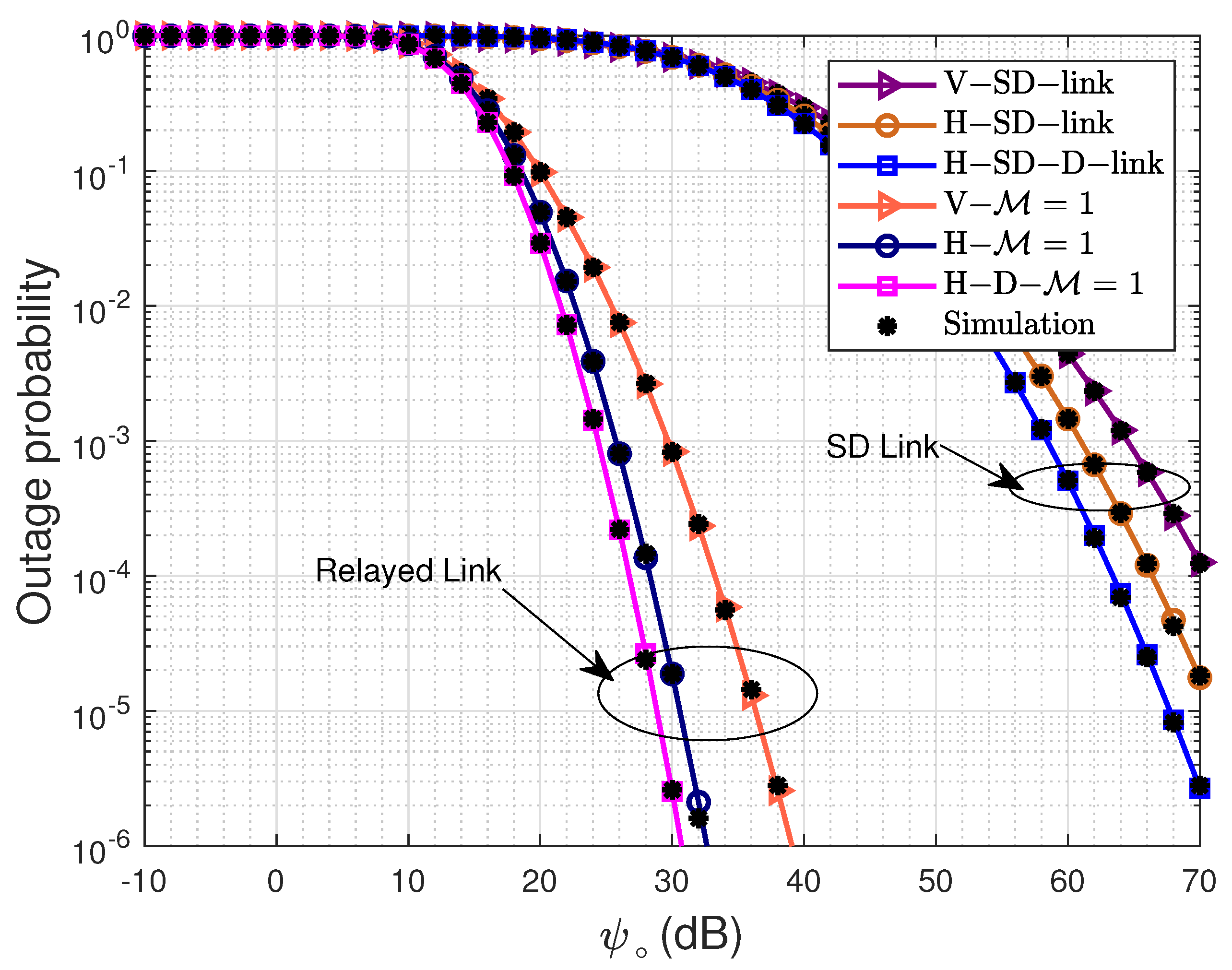
Figure 2 compares the outage probability ( P o ) of the horizontal and vertical systems for the M = 1 case, with the respective benchmark no-relay case. It can be seen that the simulation results overlap with the analytical results for all the cases, thereby validating the correctness of the derived analytical expression of the outage probability in (20). We present the outage probability curves for the vertical link (V) and two horizontal links at different depths, 10 m (H-SD) and 50 m (H-SD-D). It is observed that the relayed link clearly outperforms the direct SD link in all scenarios. Further, for both the relayed and no-relay cases, the horizontal system outperforms the vertical system. Furthermore, it can be seen that the performance of the horizontal system becomes better as we move deeper. The observed behavior is attributed to the increasing homogeneity of water at greater ocean depths, leading to diminished fluctuations in temperature, salinity, and refractive index. Reduced refractive index fluctuations lead to a smaller scintillation index value and less severe fading. As an example, for the targeted outage probability of 10 4 , using single relay results in significant SNR gains of 37.3 dB, 35.4 dB and 37.2 dB for the V- M = 1 , H- M = 1 and H-D- M = 1 cases, respectively, when compared to the respective benchmark cases. Moreover, the H- M = 1 and H-D- M = 1 systems perform better than the V- M = 1 system by 5.2 and 7 dB in the case of a relayed link, and by 4.1 dB and 7.1 dB in the case of no relay links, respectively. The horizontal system at a depth of 50 m has an SNR gain of 1.8 dB and 2.7 dB in the relayed and non-relayed systems, respectively, over the horizontal system at a depth of 10 m due to a fall in temperature, which reduces the turbulence strength.
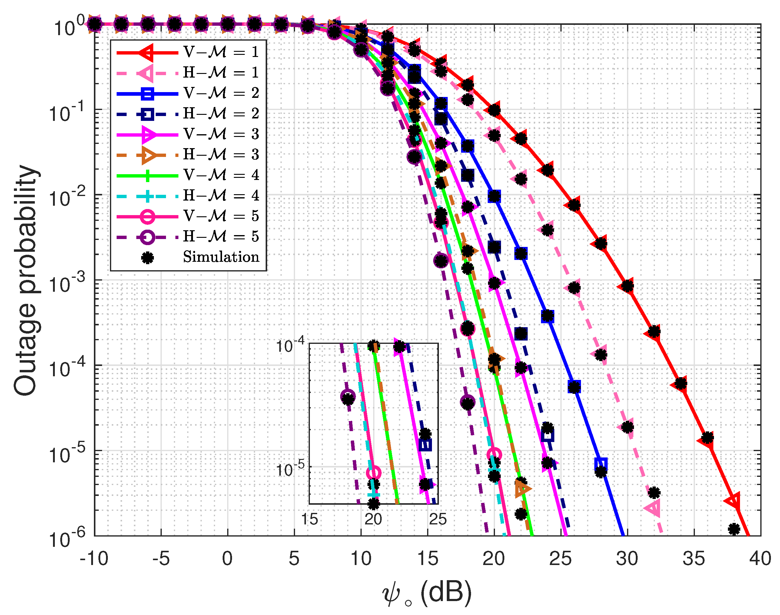
In Figure 3, the analytical and simulated outage probability curves are plotted with respect to ψ for 1 M 5 . As expected, the simulation and analytical results are overlapping. We present the curves for the vertical cascaded link and compare it with a horizontal link at a depth of 10 m. It is observed that for the target outage probability of 10 4 , employing 2 relays results in an SNR gain of 8.4 dB and 6 dB for the vertical link and horizontal link, respectively, when compared to the single relay case. It is further observed that, for M 3 , one extra relay is required in the vertical link compared to the horizontal link to achieve the same outage probability for a given SNR and link distance.
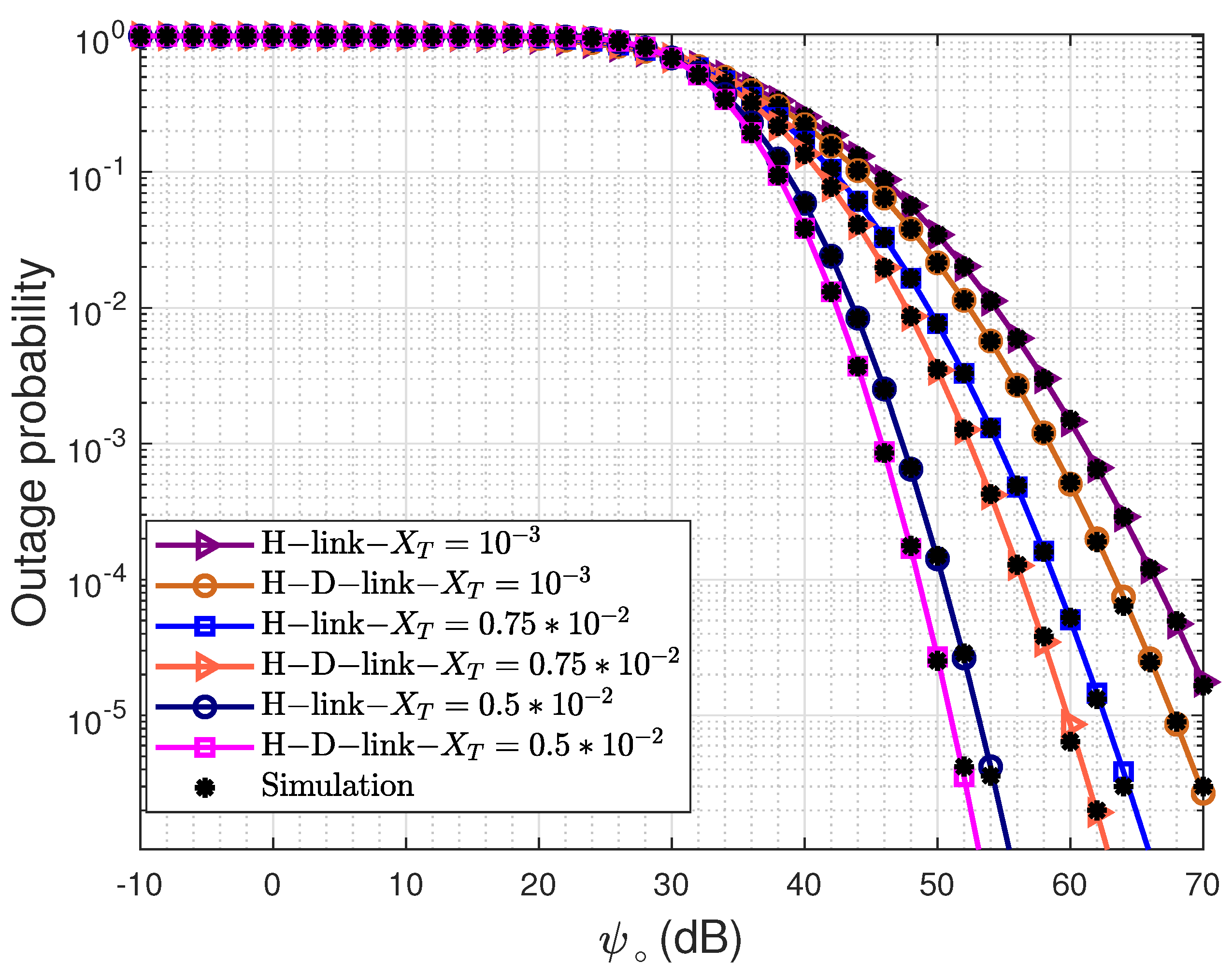
In Figure 4, the effect of the mean square temperature ( X T ) on the outage probability at different depths is studied. It is observed that for a target outage probability of 10 4 , for X T = ( 10 3 , 0.75 × 10 3 , 0.5 × 10 3 ) K 2 S 3 , an SNR of (66.1, 58.4, 50.1) dB is required at the depth of 10 m, and an SNR of ( 62.7 , 56.1 , 48.3 ) dB is required at the depth of 50 m. The presented results reveal that the outage performance improves with the reduction in the mean square temperature. Further, for the considered values of X T , a marginal reduction in the required SNR is observed at 50 m depth when compared to 10 m depth.
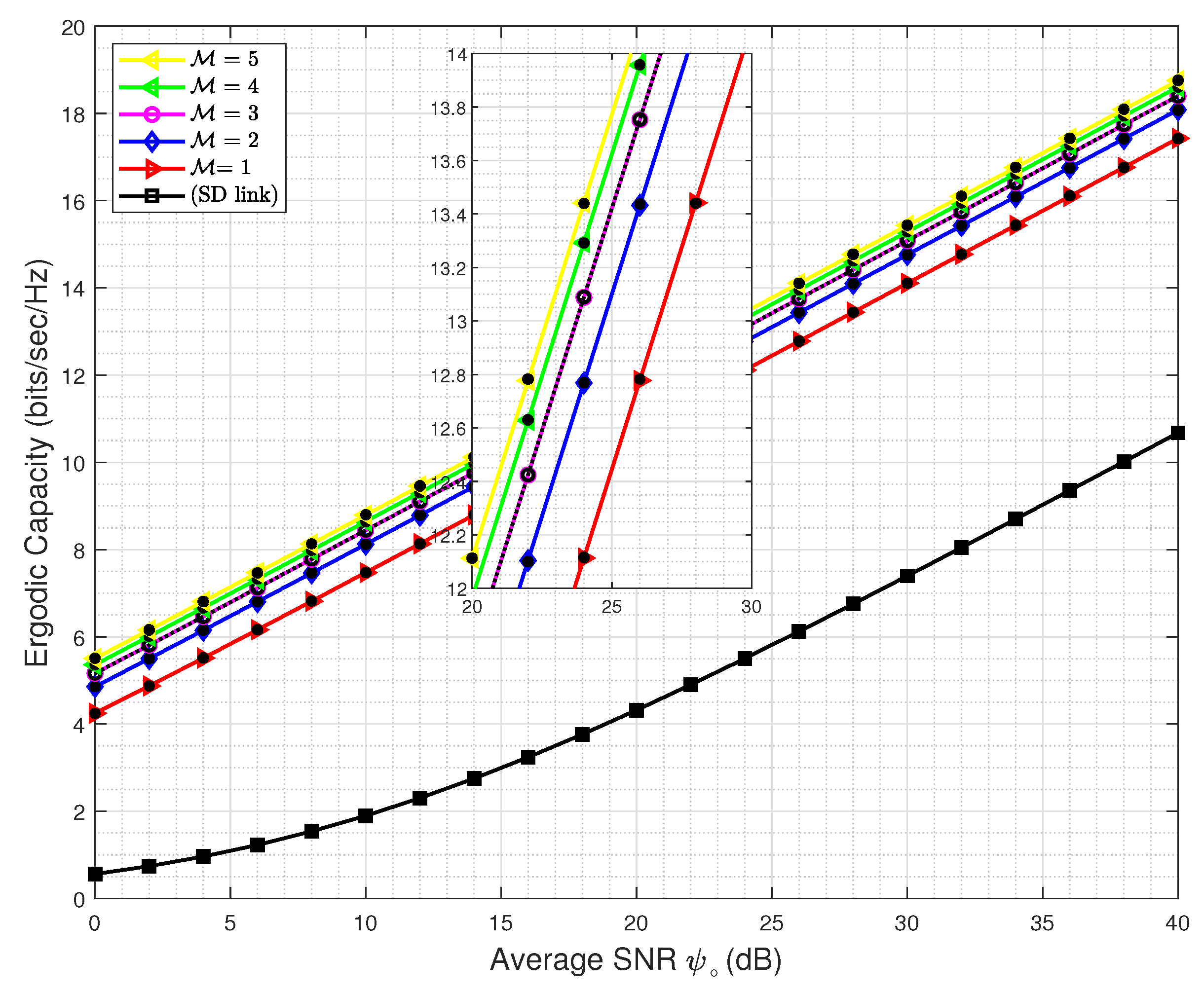
Figure 5 shows the ergodic capacity versus ψ plots for the vertical relayed and non-relay cases. The overlapping analytical and simulated plots validate the correctness of the derived ergodic capacity expression given in (30). We observe a significant increase in the capacity for the relayed case when compared to the no-relay case for both the horizontal and vertical links. Results demonstrate that at an SNR of 30 dB, a capacity of 7.5 bps/Hz and 14 bps/Hz is achieved, respectively, for the no-relay and relayed link cases with M = 1 . Further, increasing the number of relays beyond one results in the additional capacity gains of 1 , 0.5 , 0.3 bps/Hz for M = 2 , 3 , and 4 , respectively.

5. Conclusions

In this paper, we investigated a best relay selection-based cooperative UWVLC system considering both horizontal and vertical propagation. We considered the effects of both path loss and optical turbulence, and assumed constant turbulence for horizontal links and variable depth-dependent turbulence for vertical links. The turbulence was assumed to be weak and modeled using a log-normal distribution. We derived the closed-form expressions for the outage probability and ergodic capacity. We conducted a detailed simulation study and presented numerical results comparing the performance of vertical and horizontal links for varying numbers of relays and no-relay cases. It is shown that by using multiple parallel relays and the best relay selection strategy, this results in significant performance gains as compared to the no-relay case. Results reveal that the horizontal link always outperforms the vertical link irrespective of the number of relays used. To obtain similar performance to that of the horizontal link, the vertical link requires one additional relay as compared to the horizontal link for M > 3 . It is further demonstrated that the performance of the horizontal communication system improves with depth.

Author Contributions

Conceptualization, R.S., V.B. and M.A.-H.; data curation, R.S.; formal analysis, R.S., Y.N.T. and K.K.G.; investigation, R.S. and K.K.G.; methodology, R.S. and K.K.G.; resources, R.S. and K.K.G.; software, R.S.; supervision, Y.N.T. and V.B.; validation, Y.N.T., V.B. and M.A.-H.; visualization, R.S. and K.K.G.; writing—original draft, R.S., K.K.G. and Y.N.T.; writing—review and editing, R.S., K.K.G., Y.N.T., V.B. and M.A.-H. All authors have read and agreed to the published version of the manuscript.

Funding

This research received no external funding.

Institutional Review Board Statement

Not applicable.

Informed Consent Statement

Not applicable.

Data Availability Statement

Data sharing not applicable.

Acknowledgments

This work is partially funded by the Centre for Wireless Communications, University of Oulu, Finland, and the United Arab Emirates University, Al-Ain, UAE.

Conflicts of Interest

The authors declare no conflict of interest.

References

  1. Zeng, Z.; Fu, S.; Zhang, H.; Dong, Y.; Cheng, J. A survey of underwater optical wireless communications. IEEE Commun. Surv. Tuts. 2016, 19, 204–238. [Google Scholar] [CrossRef]
  2. Gussen, C.M.; Diniz, P.S.; Campos, M.; Martins, W.A.; Costa, F.M.; Gois, J.N. A survey of underwater wireless communication technologies. J. Commun. Inf. Syst. 2016, 31, 242–255. [Google Scholar] [CrossRef]
  3. Zhou, H.; Zhang, M.; Wang, X.; Ren, X. Design and Implementation of More Than 50m Real-Time Underwater Wireless Optical Communication System. J. Light. Technol. 2022, 40, 3654–3668. [Google Scholar] [CrossRef]
  4. Peng, Q.; Chen, G.; Li, X.; Liao, Q.; Guo, Y. Performance Improvement of Underwater Continuous-Variable Quantum Key Distribution via Photon Subtraction. Entropy 2019, 21, 1011. [Google Scholar] [CrossRef] [Green Version]
  5. Shin, H.; Kim, Y.; Baek, S.; Song, Y. Distributed Learning for Dynamic Channel Access in Underwater Sensor Networks. Entropy 2020, 22, 992. [Google Scholar] [CrossRef]
  6. Kaushal, H.; Kaddoum, G. Underwater Optical Wireless Communication. IEEE Access 2016, 4, 1518–1547. [Google Scholar] [CrossRef]
  7. Baykal, Y.; Ata, Y.; Gökçe, M.C. Underwater turbulence, its effects on optical wireless communication and imaging: A review. Opt. Laser Tech. 2022, 156, 108624. [Google Scholar] [CrossRef]
  8. Corporation, S. Bluecomm Underwater Optical Communication. 2020. Available online: https://www.sonardyne.com/products/bluecomm-200-wireless-underwater-link/ (accessed on 19 February 2023).
  9. Shen, C.; Guo, Y.; Sun, X.; Liu, G.; Ho, K.; Ng, T.K.; Alouini, M.; Ooi, B.S. Going beyond 10-meter, Gbit/s underwater optical wireless communication links based on visible lasers. In Proceedings of the 2017 Opto-Electronics and Communications Conference (OECC) and Photonics Global Conference (PGC), Singapore, 31 July 2017; pp. 1–3. [Google Scholar] [CrossRef] [Green Version]
  10. Jiang, H.; He, N.; Liao, X.; Popoola, W.; Rajbhandari, S. The BER Performance of the LDPC-Coded MPPM over Turbulence UWOC Channels. Photonics 2022, 9, 349. [Google Scholar] [CrossRef]
  11. Lin, Z.; Xu, G.; Zhang, Q.; Song, Z. Scintillation Index for Spherical Wave Propagation in Anisotropic Weak Oceanic Turbulence with Aperture Averaging under the Effect of Inner Scale and Outer Scale. Photonics 2022, 9, 458. [Google Scholar] [CrossRef]
  12. Millard, R.; Seaver, G. An index of refraction algorithm for seawater over temperature, pressure, salinity, density and wavelength. Deep Sea Res. Part A Oceanogr. Res. Pap. 1990, 37, 1909–1926. [Google Scholar] [CrossRef]
  13. Chester, R.; Jickells, T.D. Marine Geochemistry, 3rd ed.; Wiley Black Well: Hoboken, NJ, USA, 2012. [Google Scholar]
  14. Korotkova, O. Light propagation in a Turbulent Ocean. In Progress in Optics; Elsevier: Amsterdam, The Netherlands, 2019; Volume 64, pp. 1–43. [Google Scholar]
  15. Jamali, M.V.; Mirani, A.; Parsay, A.; Abolhassani, B.; Nabavi, P.; Chizari, A.; Khorramshahi, P.; Abdollahramezani, S.; Salehi, J.A. Statistical studies of fading in underwater wireless optical channels in the presence of air bubble, temperature, and salinity random variations. IEEE Trans. Commun. 2018, 66, 4706–4723. [Google Scholar] [CrossRef]
  16. Yao, J.R.; Elamassie, M.; Korotkova, O. Spatial power spectrum of natural water turbulence with any average temperature, salinity concentration, and light wavelength. JOSA A 2020, 37, 1614–1621. [Google Scholar] [CrossRef] [PubMed]
  17. Elamassie, M.; Miramirkhani, F.; Uysal, M. Performance Characterization of Underwater Visible Light Communication. IEEE Trans. Commun. 2019, 67, 543–552. [Google Scholar] [CrossRef]
  18. Elamassie, M.; Uysal, M. Asymptotic Performance of Generalized Transmit Laser Selection Over Lognormal Turbulence Channels. IEEE Commun. Lett. 2020, 24, 1762–1766. [Google Scholar] [CrossRef]
  19. Jamali, M.V.; Chizari, A.; Salehi, J.A. Performance analysis of multi-hop underwater wireless optical communication systems. IEEE Photon. Technol. Lett. 2017, 29, 462–465. [Google Scholar] [CrossRef]
  20. Elamassie, M.; Sait, S.M.; Uysal, M. Underwater visible light communications in cascaded gamma-gamma turbulence. In Proceedings of the 2018 IEEE Globecom Workshops (GC Wkshps), Abu Dhabi, United Arab, 9–13 December 2018; IEEE: Piscataway, NJ, USA; pp. 1–6. [Google Scholar]
  21. Elamassie, M.; Uysal, M. Performance Characterization of Vertical Underwater VLC Links in the Presence of Turbulence. In Proceedings of the 2018 11th International Symposium on Communication Systems, Networks Digital Signal Processing (CSNDSP), Budapest, Hungary, 18–20 July 2018; pp. 1–6. [Google Scholar]
  22. Akhoundi, F.; Salehi, J.A.; Tashakori, A. Cellular underwater wireless optical CDMA network: Performance analysis and implementation concepts. IEEE Trans. Commun. 2015, 63, 882–891. [Google Scholar] [CrossRef]
  23. Anous, N.; Abdallah, M.; Uysal, M.; Qaraqe, K. Performance Evaluation of LOS and NLOS Vertical Inhomogeneous Links in Underwater Visible Light Communications. IEEE Access 2018, 6, 22408–22420. [Google Scholar] [CrossRef]
  24. Elamassie, M.; Uysal, M. Vertical Underwater Visible Light Communication Links: Channel Modeling and Performance Analysis. IEEE Trans. Wirel. Commun. 2020, 19, 6948–6959. [Google Scholar] [CrossRef]
  25. Peppas, K.P.; Boucouvalas, A.C.; Ghassemloy, Z. Performance of underwater optical wireless communication with multi-pulse pulse-position modulation receivers and spatial diversity. IET Opt. 2017, 11, 180–185. [Google Scholar] [CrossRef]
  26. Elamassie, M.; Al-Nahhal, M.; Kizilirmak, R.C.; Uysal, M. Transmit Laser Selection for Underwater Visible Light Communication Systems. In Proceedings of the 2019 IEEE 30th Annual International Symposium on Personal, Indoor and Mobile Radio Communications (PIMRC), Istanbul, Turkey, 8–11 September 2019; pp. 1–6. [Google Scholar] [CrossRef]
  27. Jamali, M.V.; Salehi, J.A. On the BER of multiple-input multiple-output underwater wireless optical communication systems. In Proceedings of the 2015 4th International Workshop on Optical Wireless Communications (IWOW), Istanbul, Turkey, 7–8 September 2015; pp. 26–30. [Google Scholar] [CrossRef] [Green Version]
  28. Jamali, M.V.; Salehi, J.A.; Akhoundi, F. Performance Studies of Underwater Wireless Optical Communication Systems with Spatial Diversity: MIMO Scheme. IEEE Trans. Commun. 2017, 65, 1176–1192. [Google Scholar] [CrossRef] [Green Version]
  29. Safari, M.; Uysal, M. Cooperative diversity over log-normal fading channels: Performance analysis and optimization. IEEE Trans. Wirel. Commun. 2008, 7, 1963–1972. [Google Scholar] [CrossRef] [Green Version]
  30. Yilmaz, A.; Elamassie, M.; Uysal, M. Diversity Gain Analysis of Underwater Vertical MIMO VLC Links in the Presence of Turbulence. In Proceedings of the 2019 IEEE International Black Sea Conference on Communications and Networking (BlackSeaCom), Sochi, Russia, 3–6 June 2019; pp. 1–6. [Google Scholar] [CrossRef]
  31. Rachna, S.; N, T.Y. Performance analysis of vertical multihop cooperative underwater visible light communication system with imperfect channel state information. Opt. Eng. 2022, 61, 046106. [Google Scholar]
  32. Garg, K.K.; Shaik, P.; Singya, P.K.; Bhatia, V. Performance of Multiple Relay DF NLOS UVC System With CSI Imperfections. IEEE Open J. Commun. Soc. 2021, 2, 602–616. [Google Scholar] [CrossRef]
  33. Zhang, J.; Pan, X.; Pan, G.; Xie, Y. Secrecy Analysis for Multi-Relaying RF-FSO Systems with a Multi-Aperture Destination. IEEE Photon. J. 2020, 12, 1–11. [Google Scholar] [CrossRef]
  34. Torabi, M.; Mohammadi, N.; Nerguizian, C. Performance analysis of an asymmetric two-hop amplify-and-forward relaying RF–FSO system in a cognitive radio with partial relay selection. Opt. Commun. 2022, 505, 127478. [Google Scholar] [CrossRef]
  35. Nikishov, V.; Nikishov, V. Spectrum of turbulent fluctuations of the sea-water refraction index. Int. J. Fluid Mech. Res. 2000, 27, 82–98. [Google Scholar] [CrossRef]
  36. Ata, Y.; Yao, J.; Korotkova, O. BER variation of an optical wireless communication system in underwater turbulent medium with any temperature and salinity concentration. Opt Commun. 2021, 485, 126751. [Google Scholar] [CrossRef]
  37. Elamassie, M.; Uysal, M.; Baykal, Y.; Abdallah, M.; Qaraqe, K. Effect of eddy diffusivity ratio on underwater optical scintillation index. J. Opt. Soc. Am. 2017, 34, 1969–1973. [Google Scholar] [CrossRef]
  38. Garg, K.K.; Singya, P.K.; Bhatia, V. Performance Analysis of AF Relayed NLOS UV Communication Over Turbulent Channel. In Proceedings of the 2018 IEEE International Conference on Advanced Networks and Telecommunications Systems (ANTS), Indore, India, 16–19 December 2018; pp. 1–5. [Google Scholar] [CrossRef]
  39. Uysal, M. Cooperative Communications for Improved Wireless Network Transmission: Framework for Virtual Antenna Array Applications: Framework for Virtual Antenna Array Applications; IGI Global: Hershey, PA, USA, 2009. [Google Scholar]
  40. Abramowitz, M.; Stegun, I.A. Handbook of Mathematical Functions (National Bureau of Standards, Washington, DC, 1972), 10th ed.; Dover Publ.: Mineola, NY, USA, 1972. [Google Scholar]
  41. Andrews, L.C. Laser beam propagation through random media. In Proceedings of the SPIE-International Society for Optical Engineering; SPIE: San Diego, CA, USA, 2005. [Google Scholar]
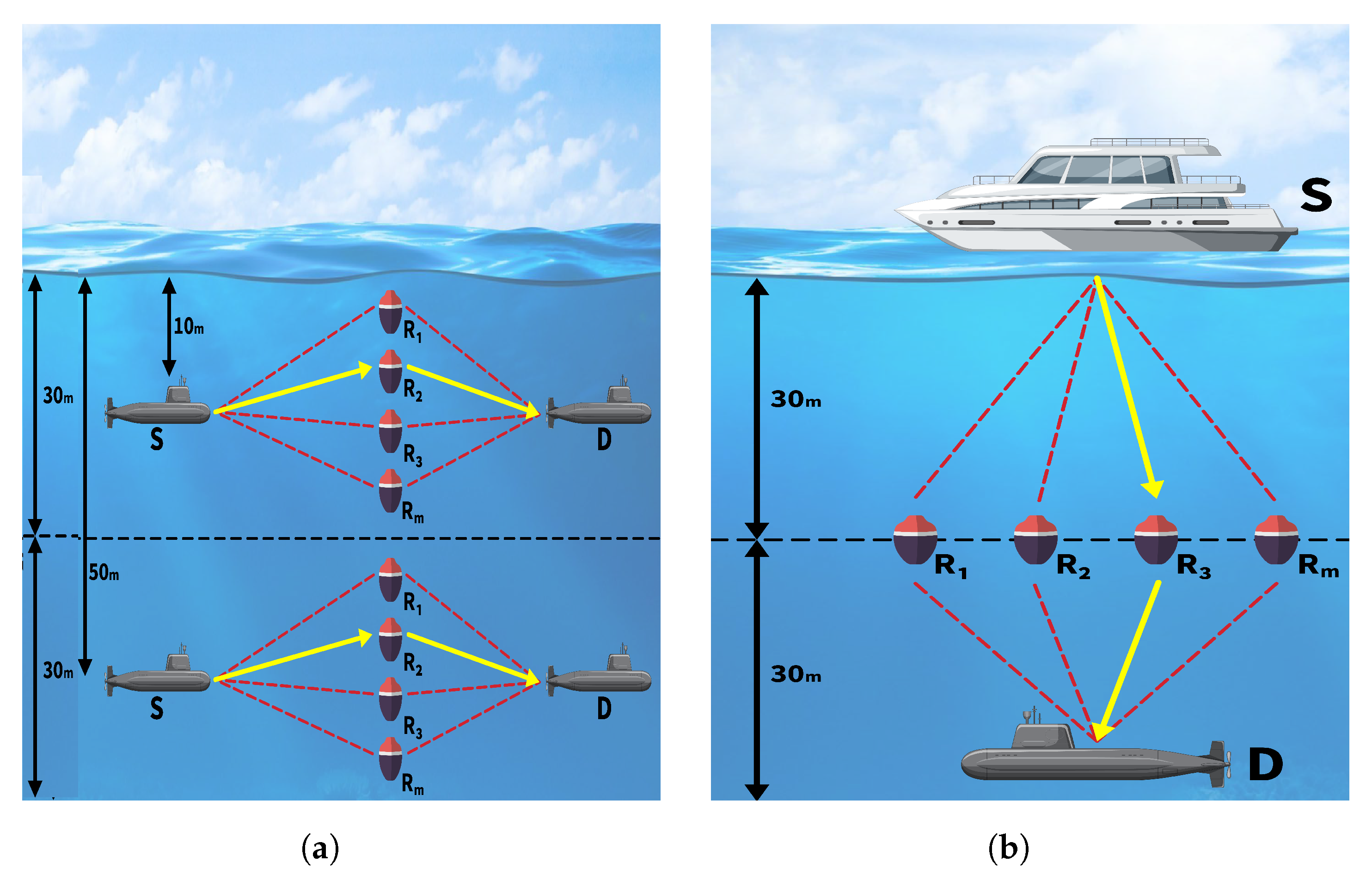
Figure 1. UWVLC cooperative communication systems. (a) Horizontal. (b) Vertical.
Photonics 10 00429 g001
Figure 2. Outage probability versus average SNR ( ψ ) dB for SD and relayed link. Symbols V, H and SD represent the vertical, horizontal and direct non-relayed link from source to destination, respectively.
Photonics 10 00429 g002
Figure 3. Outage probability ( P o ) versus average SNR ( ψ ) dB for different number of relays M .
Photonics 10 00429 g003
Figure 4. Outage probability ( P o ) versus average SNR ( ψ ) dB for different dissipation rates of mean square temperature ( X T ).
Photonics 10 00429 g004
Figure 5. Ergodic capacity ( C e ) versus average SNR ( ψ ) db. M and SD represent number of relays and direct non-relayed links from source to destination, respectively.
Photonics 10 00429 g005
Table 1. Parameters of spatial power spectrum.
ParametersValues
Wavelength λ 530 nm
Extinction coefficientsc 0.305 m 1
Correction coefficients ρ   0.13
Transmitter beam divergence angle Q F 6
Receiver aperture diameter D R 5 cm
Dissipation rate of mean square temperature χ T 10 3  K 2 s 3
Dissipation rate of turbulent kinetic energy ε 10 2  m 2 s 3
Relative strength of temperature and salinity fluctuation ω k 3
TemperatureT15.6 °C to 16.4 °C
Disclaimer/Publisher’s Note: The statements, opinions and data contained in all publications are solely those of the individual author(s) and contributor(s) and not of MDPI and/or the editor(s). MDPI and/or the editor(s) disclaim responsibility for any injury to people or property resulting from any ideas, methods, instructions or products referred to in the content.