Abstract
An integrated optomechanical analysis (IOA) can predict the response of an optomechanical system to temperature, gravity, vibrations, and other local loadings; thus, the normal operation of instruments under special conditions is guaranteed. Zernike polynomials are the most popular for fitting the IOA-derived mechanical deformation data. By solving the Zernike coefficients of all deformed optical surfaces, the relationship between aberrations and deformations can be further revealed. The process of IOA is summarized in this article. The principles of four primary Zernike coefficient-solving algorithms (CSAs) were expounded, and the corresponding applications are reviewed in detail, including the least squares method, the Gram–Schmidt orthogonalized method, the Householder transformation, and singular value decomposition (SVD). Artificial neural networks (ANNs) trained for solving a similar overdetermined set of equations are also discussed; an innovative Zernike CSA based on a one-dimensional convolutional neural network (1D-CNN) was proposed, emphasizing its potential for Zernike CSA. The feasibility of the neural network method was verified by conducting experiments on the primary mirror of the front reflection system of a space camera. This review can provide references for the precise optimization of IOA.
1. Introduction
Temperature [1], gravity [2], vibration [3], and other factors [4] seriously degrade the optical performance of an instrument and affect normal operations. An integrated optomechanical analysis (IOA) can comprehensively evaluate the impact of external environmental factors at the design stage, and it guides the design optimization of optomechanical structures using the analysis’s results, thereby significantly improving the adaptability of special optical instruments to the environment, such as aerial cameras, star sensors, space telescopes, etc. [5,6,7]. Currently, there are two main common simulation analysis methods: (1) in the traditional simulation analysis, the optomechanical system is simulated and optimized in each design process; (2) in the IOA, the overall optimization and design of the optomechanical system are carried out.
The overall design process of optical instruments primarily includes the following: optical design, optomechanical design, mechanical analysis, thermal analysis, modal analysis, and other links [8]. In traditional simulation analyses, each link is primarily used to satisfy its own indicators and relies on commercial optical, mechanical, and thermal analysis software independently. This analysis mode cannot achieve the balance optimization of optical, mechanical, thermal, and other factors, and the input conditions are limited to the internals of each link, which is challenging for forming mutual restrictions between links; moreover, enhancing the overall performance of the optomechanical system is challenging. Accordingly, Jacob Miller proposed the concept of integrated optomechanical analyses in 1981. During the design process, the response of an optical system and optomechanical structure to external environment changes is considered comprehensively, and the analysis data can also be seamlessly transferred between different designs and analysis software to achieve the overall optimization of the optomechanical system [9]. All current space optical instruments, such as the European Solar Telescope, Hale Optical Probe, Hubble Space Telescope, James Webb Space Telescope, and Keck Optical Probe, require an IOA prior to launch to verify the adaptability of optomechanical systems relative to vacuum and ultra-low temperature conditions [10,11,12,13].
The most important step in IOA is to use polynomials to fit the deformation data of optical surfaces. Zernike polynomials have orthogonality over a unit circle, and their base terms comprise radial and azimuthal variables suitable for the descriptions of circular apertures. Therefore, the Zernike polynomials are the most commonly used form in IOA. Moreover, the Zernike coefficients of deformed optical surfaces can be utilized by ray-tracing software to further analyze the relationship between deformations and aberrations, providing an efficient method of data transfer from mechanics to optics [14]. Accordingly, the accuracy of IOA is heavily dependent on the Zernike coefficient-solving algorithms (CSAs).
In the following sections, the process of IOA and its typical applications are first presented in Section 2. Zernike polynomials and the corresponding CSAs are reviewed in detail in Section 3, including the least squares method, the Gram–Schmidt orthogonalized method, the Householder transformation, and singular value decomposition (SVD). The neural networks trained for solving a similar overdetermined set of equations are also discussed in Section 4, and the potential of using neural networks to solve Zernike CSAs is analyzed. Section 5 contains the summaries on the characteristics of Zernike CSAs and suggestions for future developments.
2. Typical Applications of IOA
Thermal [15] and modal [16] analyses are two typical applications of IOA. Thermal analyses apply thermal loads to a finite element structural model of an optomechanical system based on specific temperature conditions and then calculate the temperature field under the thermal loads. When temperature fields are applied to the structural model, the thermal strain builds up and causes the displacement of finite element nodes. In order to evaluate the optical performance, the nodal displacement data of the optical surface must be converted into sag data. The Zernike coefficients of all optical surfaces are obtained by fitting the sag data with Zernike polynomials. By importing the coefficients into ray-tracing software, it is possible to quantitatively evaluate the effect of temperature changes on optical performance and, thus, provide a basis for the athermalization design of optomechanical systems.
Figure 1 is an IOA flow diagram of a satellite-borne system. According to the optical design and the satellite’s structure, the structural model of the optomechanical system is designed. Temperature analyses are carried out by using orbit parameters and extremal orbit temperatures. The thermoplastic analysis of the structural model and the temperature analysis of the optical surface together obtain the optical surface’s deformation, and the rigid body displacement of the surface is also calculated by thermoplastic analyses. The surface’s deformation is fitted by polynomials, and the fitting results and the rigid body displacement are optically analyzed together. According to the results of the optical analysis, the structure and temperature control design are optimized. A closed-loop process from the design stage to the analysis stage with respect to design optimizations is formed via IOA.
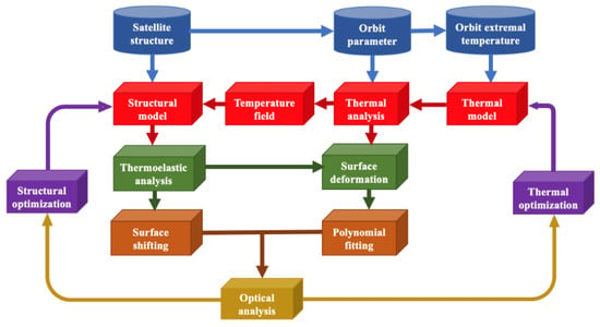
Figure 1.
An IOA flow diagram of a satellite-borne system.
For ground-based telescopes, ambient temperature changes and axial temperature gradient changes caused by direct sunlight are two key thermal factors. The Nanjing Institute of Astronomical Optics and Technology (NIAOT) evaluated the effect of ambient temperatures on the image quality of an astronomical telescope by IOA [17]. The linear interpolation technique derived from shape functions in the finite element theory was applied as an interface for the thermal model and structural model. Zernike polynomials and power series expansion were compared and used for fitting a paraboloid primary mirror with a diameter of 900 mm. Concurrently, Cho et al. [18] performed thermal analyses for the Thirty Meter Telescope’s (TMT) structure. The telescope structural parts were modeled for various thermal conditions, including air convections, conduction, heat flux loadings, and radiation. The thermal responses of the TMT’s structure were successfully predicted for daytime and nighttime periods. The CAD model of the telescope’s structure and finite element model at a Zenith angle of 30 degrees are shown in Figure 2. Deep space solar observatories need to observe the local sun, and its main mirror should not only adapt to the temperature difference between day and night periods but also avoid the influence of heat sources on the axis with respect to optical performances. In response to this complex thermal environment, Li et al. [19] used parabolic polynomials and Zernike polynomials to fit the thermal deformation of the main mirror under the supported conditions. According to the thermal analysis, the supporting system of the main reflector was improved by using a six-point support, which increased the thermal control accuracies.
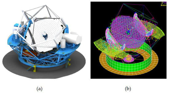
Figure 2.
(a) CAD model of telescope structure; (b) finite element model [18].
Compared with ground-based optical systems, space optical systems have a broader range of ambient temperature variations, which poses a new challenge with respect to the temperature adaptability of structures. Due to Mercury’s radiant temperature range of 100 K–700 K, the thermo-elastic analysis of high-spatial-resolution imaging cameras (HRIC) is essential for evaluating the effect of thermo-elastic deformations on optical performances under extreme thermal environmental conditions [20]. Dipasquale et al. used Zernike polynomials to decompose surface deformations induced by the piston/tilt of the two mirrors. A deformed camera with the contour plot of the displacements is shown in Figure 3. The ray-tracing results showed that the movement of the mirrors introduced a slight optical aberration; however, the pointing error can be neglected.
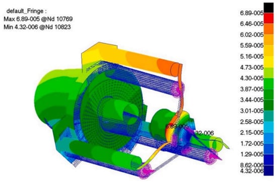
Figure 3.
Deformed telescope with a contour plot of the displacements [20].
In addition to the above large temperature difference conditions, the stability and uniformity of the ambient temperature were strictly demanded by the optical instruments used for ultra-high-precision surface measurements. Zhang et al. [21] carried out IOA on the interferometer lens, and the results revealed that the temperature difference should be less than ±0.015 °C along the mirror axis direction. In addition, Tan et al. proposed an annular-type thermal control system for eliminating the excessive heat of a large-aperture primary mirror. Moreover, thermal analyses were conducted by targeting natural and forced convection. The comparative results revealed that the thermal stability of the primary mirror with the control system significantly improved [22].
Modal analyses can predict the response of an optomechanical structure to external dynamic loads, and this is primarily divided into static analysis and vibration analysis; moreover, the analysis process is similar to thermal analysis. Static analyses are used to calculate the response of an optomechanical structure under gravity loads, forced displacements, and inertial loads [23]. For example, space optical instruments are subjected to large loads during the take-off and landing phases of a spacecraft; thus, the displacement and stress responses need to be calculated under weightlessness and overweight conditions, respectively. In contrast, the vibration environment primarily causes relative position changes among the optical components in the optical instrument, including the translation, rotation, and surface shape change in the optical components along the direction of the three axes, and ultimately affects optical performances [24]. In order to find out the reasons why the wavefront error of the space telescope did not achieve the goal, focusing on gravity, flexure bonding, and thermal expansion, Bo-Kai Huang et al. [25] analyzed the structure model of the primary mirror assembly. A new assumption of the bonding effect with zero gravity was proposed and verified by reverse engineering and the synthetic wavefront error method. Lin et al. [26] established a mathematical model based on the theory of the transfer function and line spread function to describe the influence of a carrier aircraft’s vibration on the modulation transfer function (MTF) of an aspherical aerial camera. The effectiveness of the mathematical model was validated by the results of an experimental analysis.
When large ground-based optical systems are designed and validated, it is necessary to consider the influence of modal factors, among which wind-induced vibrations are typical factors. Wind vibration analyses were performed with the baseline configuration of the Giant Magellan Telescope (GMT) structure made by Simpson Gumpertz and Heger Inc. [27]. With the wind pressure and velocity data recorded at the 8 m Gemini South Telescope as the dynamic load on GMT structure, the random response and optical errors were determined. Moreover, the areas that significantly contributed to optical errors were identified by using spectral response curves and mode shapes. The finite element model of the baseline design of the GMT telescope’s structure is shown in Figure 4.
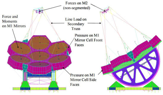
Figure 4.
Finite element model of the baseline design of the GMT telescope structure [27].
External loads, such as ambient temperature change and vibration, will eventually cause a sag change on the optical surface, leading to the degradation of optical performance. The data interface is an important part of IOA as a bridge between optical surface deformation and optical performance. The polynomials are most commonly used for fitting the sag change data on the optical surfaces in IOA, such as Zernike polynomials, annular Zernike, X-Y, Fourier–Legendre, and aspheric polynomials. By solving the fitting coefficients, wavefront variations can be quantitatively analyzed, and the relationship between deformation data and optical aberration can be established. Compared to other forms, Zernike polynomials became the most commonly used data interface due to the advantages of orthogonality over the continuous unit circle, rotation invariance, and completeness property [28]. In addition, due to the correspondence between Zernike coefficients and aberrations, commercial ray-tracking software can perform optical analysis based on Zernike coefficients without applying conversions. Accordingly, the accuracy of Zernike CSAs directly determines the accuracy of IOA results.
3. Zernike Coefficient-Solving Algorithms (CSAs)
The main Zernike CSAs include the least squares method [29], the Gram–Schmidt orthogonalized method [30], the Householder transformation [31], and singular value decomposition (SVD) [32].
3.1. Least Squares Method
Zernike polynomial fitting is used to describe the deformation of the optical surfaces of arbitrary shapes by using linear combinations of infinite bases. The discretized optical surface deformation is expressed as follows:
where ∆s is the sag change of each node, N represents the number of Zernike polynomial terms, z(r,θ) denotes the Zernike polynomials in polar form, and a is the corresponding coefficients of the Zernike polynomials. The overall optical surface deformation can be expressed as follows:
Equation (2) can be transformed into
where Z is an m × n matrix comprising Zernike polynomials, m represents the number of sampling nodes, n represents the number of terms, A is the column vector composed of Zernike coefficients, and ∆S is the column vector comprising surface sag changes. When m > n, Equation (3) is an overdetermined equation [33]. Z is the coefficient matrix of the overdetermined equation.
The Zernike polynomial coefficients can be calculated by solving the overdetermined linear equation. The overdetermined equation has no exact solution. The least squares solution of the overdetermined equation is regarded as an approximate solution, and solution A satisfies . can be decomposed by:
In this case, the minimum value is obtained for Equation (4). Equation (5) can be transformed into:
Equation (6) is known as the normal equation [34]. According to this condition, Zernike coefficients are solved by:
Wang et al. [35] analyzed the influence of temperature on the MTF of an infrared membrane diffraction optical system, and the least squares method was adopted to solve the Zernike coefficients, thus establishing the thickness distribution model of the membrane diffractive optical components. The established model was helpful for estimating the diffraction efficiency and the MTF values for various fields of view. SAGUARO is an open source software of IOA developed by the Large Optics Fabrication and Testing group at the University of Arizona, in which the least squares method is used to fit Zernike polynomials [36]. Banyal et al. [37,38] carried out IOA on solar telescope mirrors and used SAGUARO to fit the optical surface; the fitting result is shown in Figure 5. Song et al. [39] examined the effects of an irregular refractive index on optical performances and adopted the least squares method to determine the best gradient equation. The experimental results showed that the influence of the irregular refractive index effect on optical performances is one-third to one-seventh that of the thermoelastic deformation effect.
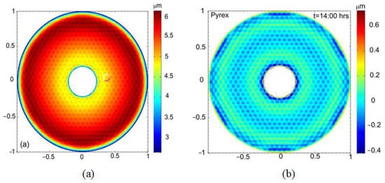
Figure 5.
(a) Surface sag for a thermally deformed Pyrex mirror; (b) residual map [37].
3.2. Gram–Schmidt Orthogonalized Method
Since IOA needs to discretize the optical surface, Zernike polynomials lose their orthogonality on the continuous unit circle. In this case, the normal equation of the overdetermined equation is ill-conditioned when the scale of the coefficient matrix is large, and the small change in the coefficient matrix leads to a drastic change in the solution vector, and the solution obtained by the least squares method becomes unstable. The orthogonality of Zernike polynomials can be improved by using the Gram–Schmidt orthogonalized method. Using the Gram–Schmidt orthogonalized method, the coefficient matrix is orthogonalized to realize the transformation of the overdetermined equation [40], and the least squares method is continually used to solve the overdetermined equation. Ill-conditioned problems due to large coefficient matrices are avoided.
Let . The linearly independent vector is transformed into orthogonal vector by using the Gram–Schmidt orthogonalized method. The orthogonalization process can be expressed as follows:
Equation (8) can then be expressed as follows:
Let and . The orthogonalization from Z to B is Z = V × B. According to Equation (9), V is defined as follows:
Equation (3) can be transformed into:
Equation (11) is the overdetermined equation after orthogonalization, and a stable solution can be obtained by solving Equation (11) using the least squares method. In addition, the Gram–Schmidt orthogonalized method can be simplified, and the covariance matrix of the coefficient matrix can be used for linear transformations to prevent the orthogonalization process and reduce the cost of computing resources [41].
Swantner et al. [42] generalized the application of Zernike polynomials with respect to annular sector apertures and verified the inference procedure by using the Gram–Schmidt orthogonalized method. Upton et al. [43] optimized the Gram–Schmidt orthogonalized method and extended the method to apertures of an arbitrary shape. Taking the hexagonal aperture as an example, the feasibility of the improved Gram–Schmidt orthogonalized method was verified. A comparison of the fitting results of Zernike polynomials in terms 7–9 is shown in Figure 6. U denotes the fitting result of the circular Zernike, and V denotes the fitting result of the orthonormal hexagonal Zernike.
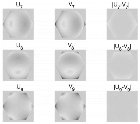
Figure 6.
Comparison charts of fitting results [43].
The ability of Zernike polynomials to characterize information on spherical cap is limited by the aperture angle. Zheng et al. [44] derived Zernike-like functions for all types of spherical caps and used the Gram–Schmidt orthogonalized method for calculations. The spherical cap’s homeomorphism maps to the unit circle, as shown in Figure 7.
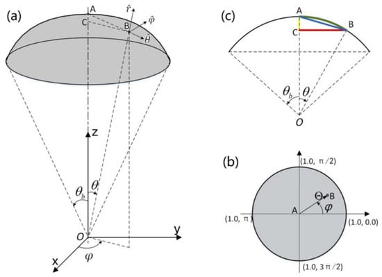
Figure 7.
Spherical cap homeomorphic mapping to a unit circle: (a) Schematic diagram of Spherical cap of semi-aperture angle; (b) Spherical cap mapping to unit circle; (c) Mapping functions in spherical cap [44].
The original intention of using the Gram–Schmidt orthogonalized method is to avoid the ill-conditioned problem of the least squares method. Although the Gram–Schmidt orthogonalized method solves ill-conditioned problems effectively, it introduces new unstable factors. When the least squares method is ill-conditioned, the orthogonal basis function system constructed by using the Gram–Schmidt orthogonalized method is correlated, which also affects the stability of the solution [45]. In addition, when the orthogonal basis functions appear to be correlated, the solution obtained before is still stable without interferences.
3.3. Householder Transformation
The Householder transformation method can solve the overdetermined equation directly without constructing the normal equation in order to avoid ill-conditioned problems in the process of solving equations. The coefficient matrix of the overdetermined equation is orthogonalized and triangulated by Householder transformations [46]. Based on the rules of Householder transformations, Z can be decomposed by the following:
where Q is an m × m orthogonal matrix, R is an n × n upper triangular matrix, and O is a (m − n) × n null matrix. The least squares solution of Equation (3) is expressed as follows.
Let . Equation (13) can then be expressed as follows:
When , the minimum value is obtained for Equation (14). According to this condition, Zernike coefficients are solved by the following:
Wang et al. [47] proposed a new method for solving active optic correction forces and simulated a 400 mm test mirror in which the Householder transformation was used to solve Zernike coefficients. The comparative results are shown in Figure 8, and the results revealed that the corrective method is effective. Cao et al. [48] described the human eye’s wavefront aberration by using Zernike polynomials and used the least squares method and Householder transformation to calculate the eye aberrations of different pupils. The calculation results showed that the accuracy of the proposed algorithm is comparable to that of the least squares method. Xiao et al. [49] established an integrated simulation method and chose the Householder transformation as a Zernike CSA. The curve of optical distortion with temperature was obtained by analyzing the objective lens.
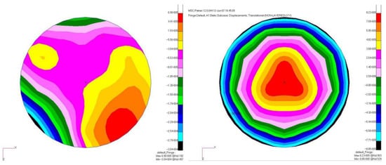
Figure 8.
Deformation plot contrast before and after correction [47].
3.4. Singular Value Decomposition (SVD)
Although the Householder transform can prevent the ill-conditioned problems of overdetermined equations, the computational complexity increases exponentially with the increase in coefficient matrix size. The SVD can enhance the efficiency and accuracy of the solution process while avoiding ill-conditioned problems [50]. Based on the rules of SVD, Z can be decomposed by:
where U is an m × m orthogonal matrix, the column vectors of which are the feature vectors of AAT; VT is an n × n orthogonal matrix, the column vectors of which are the feature vectors of ATA; Σ is a diagonal matrix composed of singular values of A.
The least squares solution of Equation (3) is expressed as follows:
The first n column vectors of U are used to form a new matrix, Um × n, and U is defined as follows:
Equation (17) can then be expressed as follows:
According to the matrix’s decomposition, the right side of Equation (19) can be transformed into:
When , the minimum value is obtained for Equation (19). According to this condition, Zernike coefficients are solved by:
When the overdetermined equation is ill conditioned, the SVD obtains smaller singular values and dramatically amplifies the variances in the solution, which makes the calculation result unreliable [51]. The truncated singular value decomposition (TSVD) can cut off the smaller singular values, which can easily cause instability, in order to obtain a reliable solution [52]. The selection of truncation parameters is the main factor affecting the optimal solution. There are two methods for selecting the truncation parameters: generalized cross validation [53] and L curve [54]. The reconstruction of three-dimensional flame temperature fields in a furnace is an overdetermined problem. Huang et al. [55] used TSVD and the L curve to reconstruct temperature fields, and the reconstructed temperature distribution is shown in Figure 9. Xie et al. [56] compared Tikhonov regularizations and TSVD in the same problem. TSVD exhibited no higher accuracies due to the truncation parameter selection problem.

Figure 9.
Reconstructed temperature profiles for typical cross sections: (a) Cross section i = 4; (b) Cross section j = 4; (c) Cross section k = 4 [55].
Currently, Zernike CSAs are broadly used. However, traditional algorithms have their own defects [57]. For reflective optical systems, they generally exhibit large aperture characteristics. In order to ensure the density of finite element nodes, the total amount of node deformation data significantly increased, and the computational complexity of traditional algorithms in the fitting process significantly increased. Although the optical surface size of the transmission optical system is generally relatively small, the number of optical surfaces is significantly more than that of the reflection optical system, which is also limited by the solution’s efficiency. At the same time, the fitting accuracy is related to the number of terms used by Zernike polynomials. It is generally believed that, if more terms are used, the fitting accuracy will be higher. However, when the number of terms exceeds 36, the traditional algorithm will have serious abnormal problems, and the selection of truncated parameters will be more challenging, reducing the accuracy of solving Zernike coefficients. Therefore, enhancing the fitting accuracy and efficiency of traditional Zernike CSAs is critically important.
4. The Potential for ANN Use in IOA
According to Equation (2), when the polar coordinates of the finite element nodes are inserted, fitting sag data essentially solve the overdetermined equation sets defined by Zernike polynomials [58]. With the development of artificial intelligence algorithms, many artificial neural networks (ANNs) have been proposed and used to solve overdetermined equation sets, such as the backpropagation neural network (BPNN) [59], convolutional neural network(CNN) [60], and recursive neural network (RNN) [61]. The training objective of artificial neural networks involves finding a mapping relationship between the input vector and output vector [62]. Therefore, an artificial neural network can be regarded as a function approximation tool. This is similar to the solution of an overdetermined equation. According to the structural similarity between ANNs and overdetermined equations [63], many fields began applying ANNs to solve their own overdetermination problem. Zhang et al. [64] presented a neural network model based on ordinary differential equations (ODE) to compute generalized and restricted singular value decompositions; the neural network’s structure for tracking the CS component is shown in Figure 10. The stability of the neural network was proven by numerical experiments, and it was applied to solve the overdetermined equation; the calculation error of the random matrix ranges from 10−15 to 10−17. The results show that the neural network can effectively solve the ill-conditioned problem of the overdetermined equation.
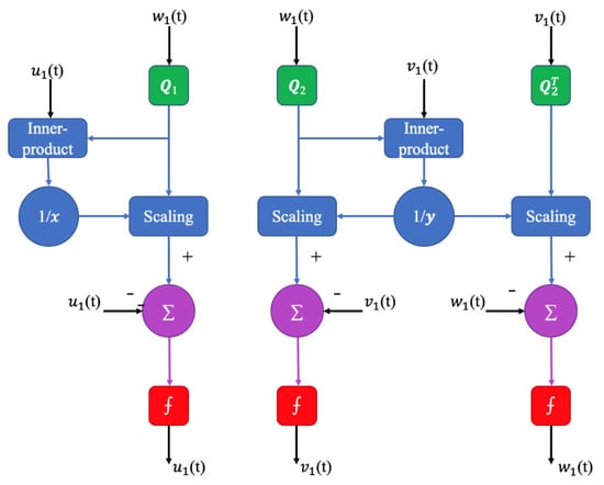
Figure 10.
Block diagram of the neural network for tracing the first CS component [64].
A Zhang neural network (ZNN) is a special RNN used to solve the time-varying overdetermined system of linear equations. Zhang et al. [65] designed two new error functions for ZNN and verified the effectiveness using computer simulations. Zhang et al. [66] proposed a varying-parameter convergent-differential neural network (VP-CDNN); the neural topology of the VP-CDNN model is shown in Figure 11 [67]. The algorithm can obtain a least squares solution with a super-exponential rate. VP-CDNN has more speed, accuracy, and robustness than RNN and zeroing neural networks. In addition, the VP-CDNN is also used to solve time-varying convex quadratic-programming problems [68].
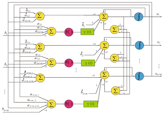
Figure 11.
Topology of the VP-CDNN model [67].
Based on these studies, using neural networks to solve the overdetermined equation is feasible. Distinct from the above cases, due to the fact that Zernike polynomials comprise one-dimensional data, it is extremely appropriate to use a one-dimensional convolutional neural network (1D-CNN) to solve Zernike coefficients. Figure 12 is a model of a one-dimensional convolutional neural network [69]. Both one-dimensional convolutional neural networks and two-dimensional convolutional neural networks have strong local sensing abilities and parameters. The only difference is that the convolutional kernel of 1D-CNN is one-dimensional, which can extract features from one-dimensional sequences; thus, it can only perform vector operations without complex matrix operations, which significantly reduces memory consumption [70]. According to this characteristic, using 1D-CNN to solve Zernike coefficients has a significantly higher computational speed than the traditional algorithm, particularly in the case of a large number of finite element nodes to be calculated.
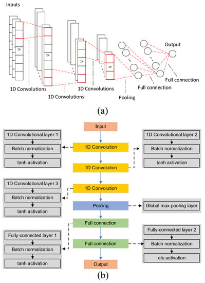
Figure 12.
A 1D CNN model: (a) model structure; (b) model architecture [69].
Training a 1D-CNN model equivalent to the overdetermined equation is the first step of solving Zernike coefficients. A 1D-CNN model usually includes an input layer, a 1D convolutional layer, pooling layer, a fully connected layer, and an output layer [71]. The Zernike polynomials of each node are taken as the input of the neural network, and the sag change is taken as the output. The number of neurons in the input layer is set according to the number of Zernike items. A convolutional layer is used to extract the features of Zernike polynomial data. The pooling layer is used to reduce the data dimension of a fully connected layer input, and it saves more detail when reducing the amount of computation. A full connection is used to learn the relationship between high-level features obtained from the pooling layer and the output. In the 1D-CNN model, the activation functions used to connect each layer primarily include sigmoid and ReLU. The function’s image is shown in Figure 13 [72]. The sigmoid function can introduce nonlinearity to 1D-CNN and enhance the learning ability of the model. The ReLU function can alleviate the problem of vanishing gradients in the neural network. The dropout technique was introduced to prevent overfitting [73,74]. By relying on the powerful prediction performance of one-dimensional convolution [75] and using the data set obtained by finite element analysis to train 1D-CNN, a model equivalent to the overdetermined equation can be obtained.

Figure 13.
Activation functions: (a) sigmoid and (b) ReLU.
The second step was to adjust the structure of 1D-CNN according to the training results. This is the most critical step, as it affects the accuracy and training efficiency of the model and further affects the final accuracy of the solution. In addition, another method for optimizing the neural network model is to change the gradient descent algorithm. Currently, common gradient descent algorithms include adaptive moment estimation (Adam), the random gradient descent algorithm (SGD), and the adaptive learning rate optimization algorithm (Adagrad). Finally, after the optimized 1D-CNN model is obtained, the identity matrix is imported into the model for the prediction of results. As a result of training, the 1D-CNN model is equivalent to the overdetermined equation. The predicted results are shown in Equation (22). Since the training error of 1D-CNN is close to 0, the predicted result can be regarded as the Zernike coefficient.
In order to verify the reliability of the above method, we conducted a test experiment. The data set for training 1D-CNN was obtained by applying finite element analysis on the primary mirror of the front reflection system of the space camera. It is a common condition that gravity direction is parallel to optical axis when the space camera is working. Therefore, the gravity response of the primary mirror when gravity direction was parallel to the optical axis was analyzed. The radius of the primary mirror was 645mm. The rigid body displacement of the primary mirror was separately input into the optical analysis in IOA; thus, the optical surface deformation that removes the rigid body displacement was fitted. Zernike polynomials select the 34-term polynomials that remove the tip/tilt/piston terms [76]. Based on the 34-term Zernike polynomial, the input of 1D-CNN is 34 terms, and the output is a node sag change. The finite element node data were divided into a training set, test set, and verification set according to the proportions of 70%:15%:15%, respectively. The results of the training are shown in Figure 14. Figure 14a shows the error histogram, and Figure 14b shows the regression distribution.
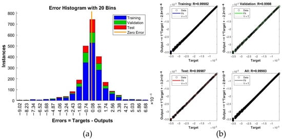
Figure 14.
Training results of 1D-CNN: (a) error histogram; (b) regression distribution.
According to the error and regression distribution of the model, the model can be regarded as equivalent to the overdetermined equation constructed by Zernike polynomials. Taking the identity matrix as the input, each Zernike coefficient was obtained. The optical surface deformation was obtained by substituting Zernike coefficients into the overdetermined equation. The fitting result of the optical surface deformation is shown in Figure 15.
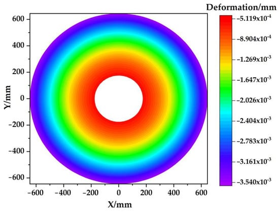
Figure 15.
Fitting result of optical surface deformation.
To verify the stability of the neural network method, a small random disturbance was applied to the data set, and the model was trained again. The verification result is shown in Figure 16. The results show that the error of the training results with a small random disturbance exhibited the same order of magnitude, and the error distribution was consistent. The accuracy of the neural network model was not affected by random errors, and the neural network method exhibited stability. The neural network method avoided the ill-conditioned problem.
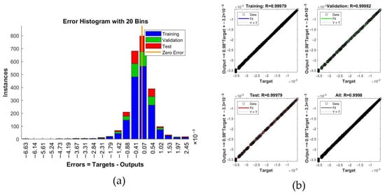
Figure 16.
Verifying training results: (a) error histogram; (b) regression distribution.
The fitting residual was obtained by subtracting the fitted sag change from the actual sag change. The fitting residual of the neural network method is shown in Figure 17. The root mean square of the residual was 17.02 nm. The average value of the ratio between the absolute value of fitting residual and the actual sag change is used as the criterion for fitting accuracies. The smaller the average ratio, the higher the fitting accuracy. The error of the neural network method was 0.864%. As a comparison, the least squares method was used to solve and fit the sag change. The error of the least squares method was 1.083%. After adding small random disturbance, the error of the neural network method was 0.872%, and the error of the least square method increased to 2.933%. Due to the robustness of neural networks, neural network methods have a strong resistance to small perturbations [77,78,79], which shows that the neural network method can effectively solve the ill-conditioned problem of the overdetermined equation. The accuracy and reliability of the proposed neural network method are verified by the above testing experiments.
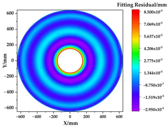
Figure 17.
Residual map obtained by the neural network method.
5. Discussion
Various past studies have shown that IOA plays an obvious role in the design of optical instruments [80,81,82], and Zernike CSAs have an important impact on the accuracy of IOA. Current Zernike CSAs have different application scenarios according to their characteristics. The least squares method is the simplest Zernike CSA. The method exhibits fast calculation speeds and can maintain calculation accuracies when the number of Zernike polynomial terms is small. However, when the number of terms is large, the solution is unstable due to ill-conditioned problems. Therefore, the least squares method is mainly applicable to the IOA of small optical instruments and optical devices that do not need to calculate more Zernike terms. The Gram–Schmidt orthogonalized method improves the Zernike polynomial and solves the ill-conditioned problem of the least squares method, but it introduces new unstable factors. In non-circular aperture optical instruments, Zernike polynomials completely lose orthogonality. For the non-circular optical instrument, using the Gram–Schmidt orthogonalized method is an effective method for orthogonalizing and then solving equations. The Householder transformation method avoids the construction of normal equations and directly solves them. It is not constrained by the number of Zernike polynomial terms and exhibits good stability and accuracy. Its computational complexity increases exponentially with the increase in data size, and it is suitable for IOAs with lesser finite element mesh. The SVD method has high computational accuracy in theory, but its application is limited by the selection of truncation parameters; thus, it is more suitable for projects with high precision requirements.
For some large-scale optical instruments, increased fine finite element meshing is usually required [76]. Banyal et al. proved that a higher order Zernike polynomial also has a certain influence on the fitting of optical surfaces [37]. Compared with the traditional algorithm, the neural network algorithm exhibits good accuracy and stability; in this case, the number of Zernike polynomial terms and grid division is no longer restricted. In addition, the working environment of some optical instruments is complex and requires multiple IOAs according to different working conditions [83,84,85]. A neural network algorithm has higher computing speeds and is more suitable for the IOAs of such optical instruments. Since the Zernike coefficient is obtained by the neural network algorithm via the direct fitting of the node data of the finite element network, the orthogonality of the Zernike term is not changed. In contrast, for the IOAs of some small optical instruments, the traditional method considers both solving efficiency and solving accuracy; thus, the traditional algorithm is the better choice.
In the test experiment, the neural network algorithm was used to achieve the surface fitting operations of the primary mirror in the front reflection system of the space camera. The RMS of the fitting residual reached 17.02 nm, and the regression evaluation index R of the neural network reached 0.9998. Compared to the least squares method, the neural network method improves the solution’s accuracy and stability. However, the neural network algorithm also has some shortcomings. Overfitting is one of the main factors affecting the fitting accuracy [86,87]. In addition, the local optimization caused by the gradient disappearance of the neural network also affects the final result [88]. Methods for avoiding these problems and for further improving fitting accuracies are the focus of future research studies.
6. Conclusions
Zernike CSAs, as an important link in the IOA that influences analysis results, are indispensable in the IOA of various optical systems in space and on Earth. The calculation accuracy of Zernike CSAs is an important factor that affects the results of IOA, and the optimization of Zernike CSAs can obtain more accurate analysis results. Currently, Zernike CSAs all have certain limitations that impede both efficiency and precision for projects requiring increasingly accurate simulations. The errors of Zernike CSAs lead to failures in obtaining accurate MTF and aberration analysis results. In this review, we summarized and analyzed traditional Zernike CSAs and combined current neural network applications when solving overdetermined equations in other fields. An innovative Zernike coefficient-solving algorithm based on a one-dimensional convolutional neural network was proposed. The neural network algorithm considered both accuracy and efficiency and increased the number of Zernike polynomial terms that can be calculated. More Zernike items can be used to analyze the higher-order aberration of optical devices. In the future, large-scale optical devices need to analyze the impact of high-order aberrations, and space projects also face more complex external environments. As a method to improve the accuracy of IOA, the neural network method is an effective solution. As hardware technology evolves and computing power advances, we expect that neural network algorithms will play an important role in IOAs.
Author Contributions
Conceptualization, Y.P.; methodology, M.H.; validation, N.Z.; formal analysis, N.Z.; investigation, X.X.; resources, X.X.; writing—original draft preparation, Y.P.; writing—review and editing, M.H.; visualization, M.H.; supervision, N.Z.; project administration, X.X.; funding acquisition, Y.P. All authors have read and agreed to the published version of the manuscript.
Funding
This research was funded by National Natural Science Foundation of China (61903048); Education Department of Jilin Province (JJKH20210824KJ); and Jilin Province Science and Technology Development Plan project (20210201029GX).
Institutional Review Board Statement
Not applicable.
Informed Consent Statement
Not applicable.
Data Availability Statement
No new data were created or analyzed in this study. Data sharing is not applicable to this article.
Conflicts of Interest
The authors declare no conflict of interest.
References
- Xue, Z.-p.; Wang, C.-x.; Yu, Y.; Wang, P.-P.; Zhang, H.-Y.; Sui, Y.-Y.; Li, M.; Luo, Z.-y. Integrated optomechanical analyses and experimental verification for a thermal system of an aerial camera. Appl. Opt. 2019, 58, 6996–7005. [Google Scholar] [CrossRef]
- Zheng, Z.; Lang, Y.; Weifeng, D.; Tianye, L.; Menjiya, T.; Yongjie, L.; Hui, W.; Xu, X. Mechanical sensitivity analysis and optimization of a large-aperture KDP frequency converter for higher SHG efficiency. Appl. Opt. 2019, 58, 2205–2215. [Google Scholar] [CrossRef] [PubMed]
- Lin, J.; Zhou, Y.; Wang, H.; Gu, Y.; Gao, M.; Guo, X.; Xu, H. Impact of microvibration on the optical performance of an airborne camera. Appl. Opt. 2021, 60, 1283–1293. [Google Scholar] [CrossRef]
- Zhou, P.; Xu, S.; Yan, C.; Zhang, X. Research on neutral surface of lightweight, horizontally supported mirror. Opt. Eng. 2018, 57, 025107. [Google Scholar] [CrossRef]
- Transon, J.; D’andrimont, R.; Maugnard, A.; Defourny, P. Survey of hyperspectral earth observation applications from space in the sentinel-2 context. Remote Sens. 2018, 10, 157. [Google Scholar] [CrossRef]
- Liu, W.; Xu, Y.; Yao, Y.; Xu, Y.; Shen, H.; Ding, Y. Relationship analysis between transient thermal control mode and image quality for an aerial camera. Appl. Opt. 2017, 56, 1028–1036. [Google Scholar] [CrossRef]
- Maamar, F.; Boudjemai, A. Optomechanical optimal design configuration and analysis of glue pad bonds in lens mounting for space application. Adv. Space Res. 2020, 65, 2263–2275. [Google Scholar] [CrossRef]
- Tinghai, Q.; Xusong, Q.; Guoqing, P.; Han, Y.; Xu, X.; Lang, Y.; Weifeng, D.; Zhao, X.; Changchun, L. Surface control apparatus and method of optical transmission with large aperture based on self-adaptive force-moment technology. Opt. Express 2017, 25, 15358–15369. [Google Scholar] [CrossRef] [PubMed]
- Miller, J.; Hatch, M.; Green, K. Predicting performance of optical systems undergoing thermal/mechanical loadings using integrated thermal/structural/optical numerical methods. Opt. Eng. 1981, 20, 166–174. [Google Scholar] [CrossRef]
- Collados, M.; Bettonvil, F.; Cavaller, L.; Ermolli, I.; Gelly, B.; Grivel-Gelly, C.; Pérez, A.; Socas-Navarro, H.; Soltau, D.; Volkmer, R. European solar telescope: Project status. In Proceedings of the Ground-Based and Airborne Telescopes III, San Diego, CA, USA, 27 June–2 July 2010; pp. 202–214. [Google Scholar]
- Amundsen, R.; Feldhaus, W.; Little, A.; Mitchum, M. Integration of Design, Structural, Thermal and Optical Analysis: And User’s Guide for Structural-to-Optical Translator (PATCOD); NAS 1.15110153, NASA-TM-110153 95N24559; Langley Research Center: Hampton, VA, USA, 1995. [Google Scholar]
- Freedman, W.L.; Madore, B.F.; Gibson, B.K.; Ferrarese, L.; Kelson, D.D.; Sakai, S.; Mould, J.R.; Kennicutt Jr, R.C.; Ford, H.C.; Graham, J.A. Final results from the Hubble Space Telescope key project to measure the Hubble constant. Astrophys. J. 2001, 553, 47. [Google Scholar] [CrossRef]
- Dalcanton, J.J. 18 years of science with the Hubble Space Telescope. Nature 2009, 457, 41–50. [Google Scholar] [CrossRef] [PubMed]
- Shao, M.; Zhang, L.; Jia, X. Optomechanical integrated optimization of a lightweight mirror for space cameras. Appl. Opt. 2021, 60, 539–546. [Google Scholar] [CrossRef]
- Gao, Y.; Zhang, B.; Chen, L.; Xu, B.; Gu, G. Thermal design and analysis of the high resolution MWIR/LWIR aerial camera. Optik 2019, 179, 37–46. [Google Scholar] [CrossRef]
- Rausch, P.; Verpoort, S.; Wittrock, U. Unimorph deformable mirror for space telescopes: Design and manufacturing. Opt. Express 2015, 23, 19469–19477. [Google Scholar] [CrossRef]
- Yang, D.; Jiang, Z.; Li, X. Integrated thermal disturbance analysis of optical system of astronomical telescope. In Proceedings of the Modeling Systems Engineering, and Project Management for Astronomy III, Marseille, France, 23–28 June 2008; pp. 526–537. [Google Scholar]
- Cho, M.; Corredor, A.; Vogiatzis, K.; Angeli, G. Thermal performance prediction of the tmt telescope structure. In Optical Modeling and Performance Predictions IV; SPIE: San Diego, CA, USA, 2009; pp. 138–152. [Google Scholar]
- LI, R.; WANG, S.; SHI, H.-l.; CHEN, Z.-p.; ZHANG, J.-y. Thermal Analysis on the Main Reflector in Deep-space Solar Observatory. Acta Photonica Sin. 2014, 43, 93–98. [Google Scholar]
- Dipasquale, D.; Debei, S.; Cremonese, G.; Capaccioni, F.; Palumbo, P. Optical performance evaluation of the high spatial resolution imaging camera of BepiColombo space mission. Opt. Laser Technol. 2021, 141, 107172. [Google Scholar] [CrossRef]
- Zhang, J.; Wu, Y.-q.; Wu, F. Thermal-structural-optical analysis for the lens of high-precision interferometer. In Proceedings of the 6th International Symposium on Advanced Optical Manufacturing and Testing Technologies: Advanced Optical Manufacturing Technologies, Xiamen, China, 26–29 April 2012; pp. 540–545. [Google Scholar]
- Tan, Y.; Wang, J.; Ren, G.; Xie, Z.; He, B. Thermal control analysis of a primary mirror for large-aperture telescope. J. Korean Phys. Soc. 2017, 71, 28–36. [Google Scholar] [CrossRef]
- Kihm, H.; Yang, H.-S. Design optimization of a 1-m lightweight mirror for a space telescope. Opt. Eng. 2013, 52, 091806. [Google Scholar] [CrossRef]
- Di Varano, I. Characterization of optical aberrations induced by thermal gradients and vibrations via Zernike and Legendre polynomials. Opt. Photonics J. 2016, 6, 113–123. [Google Scholar] [CrossRef]
- Huang, B.-K.; Huang, P.-H. Finite element and wavefront error analysis of the primary mirror of an experimental telescope with reverse engineering. In Optical Modeling and Performance Predictions VIII; SPIE: San Diego, CA, USA, 2016; pp. 158–166. [Google Scholar]
- Lin, J.; Tian, J.; Lu, M.; Ran, T.; Zhou, J. Modeling and experimental analysis on the effect of carrier aircraft vibration on the imaging quality of an aspherical aerial camera. Optik 2021, 232, 166571. [Google Scholar] [CrossRef]
- Kan, F.W.; Eggers, D.W. Wind vibration analyses of giant Magellan telescope. In Proceedings of the Modeling, Systems Engineering, and Project Management for Astronomy II, Orlando, FL, USA, 30–31 May 2006; SPIE: San Diego, CA, USA, 2006; pp. 271–283. [Google Scholar]
- Lee, H. Use of Zernike polynomials for efficient estimation of orthonormal aberration coefficients over variable noncircular pupils. Opt. Lett. 2010, 35, 2173–2175. [Google Scholar] [CrossRef] [PubMed]
- Cruces, S. Bounded component analysis of noisy underdetermined and overdetermined mixtures. IEEE Trans. Signal Process. 2015, 63, 2279–2294. [Google Scholar] [CrossRef]
- Du, H.; Gao, H. Three-frame self-calibration phase shift algorithm using the Gram–Schmidt orthonormalization approach. Appl. Opt. 2016, 55, 6713–6717. [Google Scholar] [CrossRef]
- Noble, J.H.; Lubasch, M.; Stevens, J.; Jentschura, U.D. Diagonalization of complex symmetric matrices: Generalized Householder reflections, iterative deflation and implicit shifts. Comput. Phys. Commun. 2017, 221, 304–316. [Google Scholar] [CrossRef]
- Bai, X.; Huang, G.-X.; Lei, X.-J.; Reichel, L.; Yin, F. A novel modified TRSVD method for large-scale linear discrete ill-posed problems. Appl. Numer. Math. 2021, 164, 72–88. [Google Scholar] [CrossRef]
- Liao, M.; Liu, Y.; Shang, S.-L.; Zhou, F.; Qu, N.; Chen, Y.; Lai, Z.; Liu, Z.-K.; Zhu, J. Elastic3rd: A tool for calculating third-order elastic constants from first-principles calculations. Comput. Phys. Commun. 2021, 261, 107777. [Google Scholar] [CrossRef]
- Kusche, J. On fast multigrid iteration techniques for the solution of normal equations in satellite gravity recovery. J. Geodyn. 2002, 33, 173–186. [Google Scholar] [CrossRef]
- Wang, D.; Zhi, X.; Zhang, W.; Yin, Z.; Jiang, S.; Niu, R. Influence of ambient temperature on the modulation transfer function of an infrared membrane diffraction optical system. Appl. Opt. 2018, 57, 9096–9105. [Google Scholar] [CrossRef]
- Kim, D.W.; Lewis, B.J.; Burge, J.H. Open-source data analysis and visualization software platform: SAGUARO. In Proceedings of the Optical Manufacturing and Testing IX, San Diego, CA, USA, 22–24 August 2011; SPIE: San Diego, CA, USA, 2011; pp. 75–84. [Google Scholar]
- Banyal, R.K.; Ravindra, B.; Chatterjee, S. Opto-thermal analysis of a lightweighted mirror for solar telescope. Opt. Express 2013, 21, 7065–7081. [Google Scholar] [CrossRef]
- Banyal, R.K.; Ravindra, B. Thermal characteristics of a classical solar telescope primary mirror. New Astron. 2011, 16, 328–336. [Google Scholar] [CrossRef]
- Song, X.; Li, L.; Huang, Y. Method of determining effects of heat-induced irregular refractive index on an optical system. Appl. Opt. 2015, 54, 7701–7707. [Google Scholar] [CrossRef] [PubMed]
- Wei, M.; Liu, Q. Roundoff Error Estimates of the Modified Gram–Schmidt Algorithm with Column Pivoting. Bit Numer. Math. 2003, 43, 627–645. [Google Scholar] [CrossRef]
- Amiri-Simkooei, A. Weighted total least squares with singular covariance matrices subject to weighted and hard constraints. J. Surv. Eng 2017, 143, 04017018. [Google Scholar] [CrossRef]
- Swantner, W.; Chow, W.W. Gram–Schmidt orthonormalization of Zernike polynomials for general aperture shapes. Appl. Opt. 1994, 33, 1832–1837. [Google Scholar] [CrossRef]
- Upton, R.; Ellerbroek, B. Gram–Schmidt orthogonalization of the Zernike polynomials on apertures of arbitrary shape. Opt. Lett. 2004, 29, 2840–2842. [Google Scholar] [CrossRef]
- Zheng, Y.; Wei, K.; Liang, B.; Li, Y.; Chu, X. Zernike like functions on spherical cap: Principle and applications in optical surface fitting and graphics rendering. Opt. Express 2019, 27, 37180–37195. [Google Scholar] [CrossRef]
- Mo, W.-D.; Fan, Q.; Zhang, H.-F.; Feng, M.-D.; Yang, B.-Y.; Jia, J.-C. The research on equivalence of the algorithms in fitting interference wave surface with zernike polynomials. J. Air Force Eng. Univ. (Nat. Sci.) 2010, 11. [Google Scholar] [CrossRef]
- Van De Geijn, R.A.; Van Zee, F.G. High-performance up-and-downdating via householder-like transformations. ACM Trans. Math. Softw. (TOMS) 2011, 38, 1–17. [Google Scholar] [CrossRef]
- Wang, F.-g.; Yang, F.; Wu, X.-x.; Liu, H.-w. Based on householder transform of the Zernike polynomial wavefront fitting method to solve active optics correction force. In Proceedings of the Infrared Materials, Devices, and Applications, Beijing, China, 12–15 November 2007; SPIE: San Diego, CA, USA, 2008; pp. 509–513. [Google Scholar]
- CAO, Z.; Liao, W.; Shen, J. A new algorithm for human eye’s wave-front aberration fitting with Zernike polynomial. Opt. Precis. Eng. 2006, 14, 308–314. [Google Scholar]
- Xiao, Y.; Xu, W.; Zhao, C. Integrated Simulation of Opto-Mechanical System. Acta Opt. Sin. 2016, 36, 247–254. [Google Scholar]
- Bouhamidi, A.; Jbilou, K.; Reichel, L.; Sadok, H.; Wang, Z. Vector extrapolation applied to truncated singular value decomposition and truncated iteration. J. Eng. Math. 2015, 93, 99–112. [Google Scholar] [CrossRef]
- Li, Z.C.; Huang, H.T.; Wei, Y. Ill-conditioning of the truncated singular value decomposition, Tikhonov regularization and their applications to numerical partial differential equations. Numer. Linear Algebra Appl. 2011, 18, 205–221. [Google Scholar] [CrossRef]
- Xu, P. Truncated SVD methods for discrete linear ill-posed problems. Geophys. J. Int. 1998, 135, 505–514. [Google Scholar] [CrossRef]
- Gan, M.; Zhu, H.-T.; Chen, G.-Y.; Chen, C.P. Weighted generalized cross-validation-based regularization for broad learning system. IEEE Trans. Cybern. 2020, 52, 4064–4072. [Google Scholar] [CrossRef]
- Zhou, K.; Zhang, S.; Huang, Z.; Zhang, J. An improved TSVD-GCV inversion algorithm of pore size distribution in time-domain induced polarization using migration Hankel matrix. J. Pet. Sci. Eng. 2019, 183, 106368. [Google Scholar] [CrossRef]
- Huang, Q.-X.; Liu, D.; Wang, F.; Yan, J.-H.; Chi, Y.; Cen, K.-F. Study on three-dimensional flame temperature distribution reconstruction based on truncated singular value decomposition. Acta Phys. Sin. 2007, 56, 6742–6748. [Google Scholar] [CrossRef]
- Xie, Z.-C.; Wang, F.; Yan, J.-H.; Cen, K.-F. Comparative studies of Tikhonov regularization and truncated singular value decomposition in the three-dimensional flame temperature field reconstruction. Acta Phys. Sin. 2015, 64, 21–28. [Google Scholar]
- Lu, L.; Hou, Q. Wavefront fitting with Zernike polynomials based on total variation regularization method. In Proceedings of the Optical Design and Testing V, Beijing, China, 5–7 November 2012; pp. 465–472. [Google Scholar]
- Coronato, P.A.; Juergens, R.C. Transferring FEA results to optics codes with Zernikes: A review of techniques. Optomechanics 2003 2003, 5176, 1–8. [Google Scholar]
- Jin, X.; Liu, Q.; Long, H. Impact of cost–benefit analysis on financial benefit evaluation of investment projects under back propagation neural network. J. Comput. Appl. Math. 2021, 384, 113172. [Google Scholar] [CrossRef]
- Hu, Q.; Souza, L.F.d.F.; Holanda, G.B.; Alves, S.S.; Silva, F.H.d.S.; Han, T.; Reboucas Filho, P.P. An effective approach for CT lung segmentation using mask region-based convolutional neural networks. Artif. Intell. Med. 2020, 103, 101792. [Google Scholar] [CrossRef]
- Petmezas, G.; Haris, K.; Stefanopoulos, L.; Kilintzis, V.; Maglaveras, N. Automated Atrial Fibrillation Detection using a Hybrid CNN-LSTM Network on Imbalanced ECG Datasets. Biomed. Signal Process. Control 2021, 63, 102194. [Google Scholar] [CrossRef]
- Xia, M.; Wang, T.; Zhang, Y.; Liu, J.; Xu, Y. Cloud/shadow segmentation based on global attention feature fusion residual network for remote sensing imagery. Int. J. Remote Sens. 2021, 42, 2022–2045. [Google Scholar] [CrossRef]
- Li, Y.; Cao, W. An extended multilayer perceptron model using reduced geometric algebra. IEEE Access 2019, 7, 129815–129823. [Google Scholar] [CrossRef]
- Zhang, L.; Wei, Y.; Chu, E.K.-w. Neural network for computing GSVD and RSVD. Neurocomputing 2021, 444, 59–66. [Google Scholar] [CrossRef]
- Zhang, Y.; Li, W.; Guo, D.; Mu, B.; Zheng, H. Different Zhang functions leading to various ZNN models illustrated via solving the time-varying overdetermined system of linear equations. In Proceedings of the 2013 IEEE Third International Conference on Information Science and Technology (ICIST), Yangzhou, China, 23–25 March 2013; IEEE: Piscataway, NJ, USA, 2013; pp. 771–776. [Google Scholar]
- Zhang, Z.; Zheng, L.; Qiu, T.; Deng, F. Varying-parameter convergent-differential neural solution to time-varying overdetermined system of linear equations. IEEE Trans. Autom. Control 2019, 65, 874–881. [Google Scholar] [CrossRef]
- Zhang, Z.; Deng, X.; Zheng, L. A review on varying-parameter convergence differential neural network. Neurocomputing 2022, 490, 54–65. [Google Scholar] [CrossRef]
- Zhang, Z.; Lu, Y.; Zheng, L.; Li, S.; Yu, Z.; Li, Y. A new varying-parameter convergent-differential neural-network for solving time-varying convex QP problem constrained by linear-equality. IEEE Trans. Autom. Control 2018, 63, 4110–4125. [Google Scholar] [CrossRef]
- Qian, C.; Xu, B.; Chang, L.; Sun, B.; Feng, Q.; Yang, D.; Ren, Y.; Wang, Z. Convolutional neural network based capacity estimation using random segments of the charging curves for lithium-ion batteries. Energy 2021, 227, 120333. [Google Scholar] [CrossRef]
- Xiao, D.; Chen, Y.; Li, D.U. One-Dimensional Deep Learning Architecture for Fast Fluorescence Lifetime Imaging. IEEE J. Sel. Top. Quantum Electron. 2021, 27, 1–10. [Google Scholar] [CrossRef]
- Davood, M. One-dimensional deep learning inversion of electromagnetic induction data using convolutional neural network. Geophys. J. Int. 2020, 222, 247–259. [Google Scholar]
- Li, X.; Lu, R.; Wang, Q.; Wang, J.; Zhou, Y. One-dimensional convolutional neural network (1D-CNN) image reconstruction for electrical impedance tomography. Rev. Sci. Instrum. 2020, 91, 124704. [Google Scholar] [CrossRef]
- Du, M.; Bi, S.; Zhang, X.; Li, Y.; Li, T.; Shi, R. Mode angular degree identification in subgiant stars with convolutional neural networks based on power spectrum. Mon. Not. R. Astron. Soc. 2020, 501, 614–622. [Google Scholar] [CrossRef]
- Dos, S.; Paulo, P.J. Avoiding Overfitting: A Survey on Regularization Methods for Convolutional Neural Networks. ACM Comput. Surv. (CSUR) 2021, 54, 1–25. [Google Scholar]
- Yang, Z.; Xu, P.; Zhang, B.; Xu, C.; Zhang, L.; Xie, H.; Duan, Q. Nuclear power plant sensor signal reconstruction based on deep learning methods. Ann. Nucl. Energy 2022, 167, 108765. [Google Scholar] [CrossRef]
- Borden, M.; Lewis, D.; Ochoa, H.; Jones-Wilson, L.; Susca, S.; Porter, M.; Massey, R.; Clark, P.; Netterfield, B. Thermal, Structural, and Optical Analysis of a Balloon-Based Imaging System. Publ. Astron. Soc. Pac. 2017, 129, 035001. [Google Scholar] [CrossRef]
- Chen, W.; Zhu, L.; Loo, S.Y.; Wang, J.; Wang, C.; Meng, Q.H.; Zhang, H. Robustness Improvement of Using Pre-Trained Network in Visual Odometry for On-Road Driving. IEEE Trans. Veh. Technol. 2021, 70, 12415–12426. [Google Scholar] [CrossRef]
- Zheng, Y.; Lin, L.; Zhang, T.; Chen, H.; Duan, Q.; Xu, Y.; Wang, X. Enabling Robust DRL-Driven Networking Systems via Teacher-Student Learning. IEEE J. Sel. Areas Commun. 2022, 40, 376–392. [Google Scholar] [CrossRef]
- Couellan, N. Probabilistic robustness estimates for feed-forward neural networks. Neural Netw. 2021, 142, 138–147. [Google Scholar] [CrossRef] [PubMed]
- Zhang, Z.; Quan, X.; Wang, H.; Liu, T.; Xiong, Z.; Yuan, X.; Rong, Y. Optomechanical analysis of the flexure mounting configuration of large-aperture laser transport mirror. Opt. Eng. 2017, 56, 025103. [Google Scholar] [CrossRef]
- Chen, D.; Yu, Y.; Chu, D.; Wang, H. Performance analysis and optimization of inertial confinement fusion cascaded frequency converters based on the integrated optomechanical method. Opt. Eng. 2020, 59, 105101. [Google Scholar] [CrossRef]
- Chalifoux, B.D.; Heilmann, R.K.; Schattenburg, M.L. Correcting flat mirrors with surface stress: Analytical stress fields. JOSA A 2018, 35, 1705–1716. [Google Scholar] [CrossRef] [PubMed]
- Chen, Y.C.; Huang, B.K.; You, Z.T.; Chan, C.Y.; Huang, T.M. Optimization of lightweight structure and supporting bipod flexure for a space mirror. Appl. Opt. 2016, 55, 10382–11039. [Google Scholar] [CrossRef]
- Dong, T.; Han, X.; Chen, C.; Li, M.; Fu, Y. Research on a wavefront aberration calculation method for a laser energy gradient attenuator. Laser Phys. Lett. 2013, 10, 096001. [Google Scholar] [CrossRef]
- Wei, L.; Zhang, L.; Gong, X.; Ma, D.M. Design and optimization for main support structure of a large-area off-axis three-mirror space camera. Appl. Opt. 2017, 56, 1094. [Google Scholar] [CrossRef]
- Wei, Y.; Duan, Q.; Yuan, R.; Yan, X.; Yang, Y. Dropout neuronal unit with tunable probability based on NbO_x stochastic memristor for efficient suppression of overfitting. Microelectron. Eng. 2022, 259, 111778. [Google Scholar] [CrossRef]
- Xie, Z.; He, F.; Fu, S.; Sato, I.; Tao, D.; Sugiyama, M. Artificial Neural Variability for Deep Learning: On Overfitting, Noise Memorization, and Catastrophic Forgetting. Neural Comput. 2021, 33, 2163–2192. [Google Scholar] [CrossRef]
- D’Archivio, A.A.; Maggi, M.A.; Ruggieri, F. Artificial neural network prediction of multilinear gradient retention in reversed-phase HPLC: Comprehensive QSRR-based models combining categorical or structural solute descriptors and gradient profile parameters. Anal. Bioanal. Chem. 2015, 407, 1181–1190. [Google Scholar] [CrossRef] [PubMed]
Disclaimer/Publisher’s Note: The statements, opinions and data contained in all publications are solely those of the individual author(s) and contributor(s) and not of MDPI and/or the editor(s). MDPI and/or the editor(s) disclaim responsibility for any injury to people or property resulting from any ideas, methods, instructions or products referred to in the content. |
© 2023 by the authors. Licensee MDPI, Basel, Switzerland. This article is an open access article distributed under the terms and conditions of the Creative Commons Attribution (CC BY) license (https://creativecommons.org/licenses/by/4.0/).