Article

Research on 2D Image Motion Compensation for a Wide-Field Scanning Imaging System with Moving Base

1
Xi’an Institute of Optics and Precision Mechanics, Chinese Academy of Sciences, Xi’an 710119, China
2
University of Chinese Academy of Sciences, Beijing 100049, China
*
Author to whom correspondence should be addressed.
Photonics 2023, 10(12), 1305; https://doi.org/10.3390/photonics10121305
Submission received: 11 October 2023 / Revised: 13 November 2023 / Accepted: 23 November 2023 / Published: 26 November 2023

Abstract

:
The wide-field imaging system carried on a high-altitude or near-space vehicle takes high-resolution images of the ground to measure and map targets. With the improvement of imaging resolution and measurement accuracy, the focal length of the wide-field imaging system is getting longer. The requirement for image motion compensation (IMC) accuracy is getting higher, and the influence of optical path coupling is increasing within the process of two-dimensional (2D) IMC. To further improve the IMC accuracy of the wide-field imaging system, an innovative IMC method is first proposed in this paper. The method is based on the 2D motion of the scanning platform and secondary mirror. Secondly, to solve the optical coupling problem in the process of 2D IMC, the coupling phenomenon is analyzed. The coupling relationships between 2D scanning motion, 2D secondary mirror motion and image motion is derived from the compensation process. A complete 2D IMC model is established, and a 2D IMC method, including an optical path decoupling correct regulator (ODCR), is designed. Finally, the method is verified in laboratory and field flight tests. The results show that the proposed method can effectively correct the coupling error of the optical path in the process of IMC and achieve high-resolution 2D IMC. When the scanning speed is 60°/s and the exposure time is 2 ms, the accuracy of the 2D IMC is up to 0.57pixels (RMS) in the pitch direction, and 0.46 pixels (RMS) in the roll direction.

1. Introduction

A wide-field imaging system takes photos from the base of a high-altitude platform. Due to the vibration and motion of the high-altitude platform, as well as camera scanning, there is relative movement between the image and the photo-sensitive medium when the camera is exposed. This results in a slight blurring and tailing effect, which is called the image motion. IMC capability is the main factor in verifying the detective performance of the current wide-field imaging system. In particular, the advent of remote high-resolution telephoto cameras has advanced the requirements for higher technology of the IMC [1,2]. In terms of different causes, there are four types of image motion, including forward image motion caused by flight of the carrier, random image motion caused by attitude change of the carrier, scanning image motion caused by optical system scanning, and vibration image motion caused by the vibration of the carrier. However, these image motions can be decomposed into the 2D orthogonal direction at the compensation stage.
In recent years, researchers have proposed a variety of strategies for IMC, which can mainly be summarized into three categories, including image compensation, optical compensation and hybrid electronic and optical compensation. Image compensation is to deblur the image via the image degradation model [3,4]. This method has the advantages of low cost and strong flexibility. But for the image acquired in wide-area reconnaissance mode, the amount of data is too large to be processed, and the real-time performance is poor. The hybrid electronic and optical compensation method compensates for the forward image motion through the front 45° mirror and compensates for the scanning of the image through TDI CCD. The charge transfer driving technology is used to match the charge transfer speeds with the moving line speed of the scene, thus compensating for the the image motion in a dynamic balance. In this compensation method, the 45° front mirror has a large size, and TDI is a linear array detector, which requires the integration time of TDI CCD to match the image motion velocity [5,6,7,8]. Imaging of the TDI CCD camera must be performed through the push-broom or whisk-broom system, and the operator cannot keep the visual axis pointing at and continuously monitoring the target.
The optical compensation method combines the area array detector and the IMC mechanism. With the increasing focal length of the imaging systems and their improved mapping efficiency, this method is the usual method for IMC at present. However, some of the existing optical compensation methods focus on the design and research of the fast-steering mirror system (FSM) [9,10,11]. Others focus on the conceptual research of one-dimensional (1D) directional IMC [12,13,14,15,16,17,18], which adopts the 1D motion of the FSM for IMC. In these methods, the FSM compensation motion and the scanning motion are simply added as composite image motion [18,19], on the assumption that the FSM compensating motion is in the same direction as the image motion. When the scanning speed is low (below 20°/s), the amount of image motion is less. In this case, the influence of optical path coupling is small, and the accuracy of IMC can meet the requirements of imaging quality using existing methods [13,14,18]. However, when it is necessary to increase the scanning rate to improve imaging efficiency, the amount of image motion increases, and the influence of optical path coupling is notable. In 2D IMC, orthogonal error is inevitable in 2D FSM compensating motion, and the 2D FSM compensating motion is not precisely in the same direction as the practical image motion, which will also cause an optical coupling phenomenon and directly restrict the accuracy of 2D IMC. Unfortunately, few research efforts are being initiated on 2D IMC.
In order to solve the above problems and achieve high-precision 2D IMC, this paper draws on the existing linear array and staring array wide-field imaging system methods, and the main innovations are as follows:
  • A multilevel 2D IMC method is proposed in this paper. The coarse and fine 2D IMC are achieved through a 2D scanning platform and 2D FSM. Distinct from the traditional 1D IMC method which adopts a discrete compensation mechanism for each dimension, in this paper, the compensation of 2D image motion is set in one compensation mechanism and placed in the secondary mirror position. The 2D IMC mechanism is more compact, more efficient and more accurate.
  • In order to achieve accurate compensation of 2D image motion, the 2D compensating motion of the secondary mirror in the process of dynamic compensation must be exactly consistent with the 2D image motion in direction and magnitude. In practice, consistency is hard to guarantee, so it is not possible to simply add FSM compensation motion and scanning motion up to determine a synthetic image motion. Additionally, as opposed to 1D IMC, 2D IMC is difficult and has orthogonal errors. In view of this, the coupling relationship between the image motion and compensating motion is derived and analyzed with the image coordinate system as the medium, and a complete 2D IMC model is established from the coupling relationship.
  • Based on the complete system model, a 2D IMC method with ODCR is designed to achieve high-precision 2D IMC. Then, the coupling relationship is calibrated. Additionally, experiments are carried out both in laboratory and flight tests to verify the efficiency and accuracy of the 2D IMC method.

2. System Components and Operating Principle

The multilevel 2D IMC system proposed in this paper is composed of coarse and fine image stabilization parts, both of which are 2D mechanisms. They actively cooperate with each other to achieve the multilevel IMC. The coarse image part is a two-axis scanning stabilization platform, with the outer rolling frame rotating along the flight direction and the inner pitch frame axis rotating along the direction of pitch. Two staring-array cameras, splicing to expand the heading field of view, and a gyro are installed in the inner pitch frame. The staring array camera adopts a Cassegrain optical system, and the 2D FSM is installed in the secondary mirror position, creating a fine IMC mechanism. The structure of the multilevel 2D IMC system is shown in Figure 1.
The principle of the IMC is introduced below. According to the wide-field imaging parameters such as overlap and field of view (FOV), the outer rolling gimbal of the 2D coarse platform dynamically scans along the span direction at a set speed relative to the inertial space, so as to realize the combination of scanning motion and primary stable motion, compensating for the image motions of attitude change, carrier vibration and flight motion in the wingspan direction. While scanning the outer rolling gimbal, the inner pitch gimbal moves back in a small range to compensate for the image motions of attitude change, carrier vibration and flight motion in the flight direction. The two-axis gyro senses the image movement in two dimensions. The pitch axis senses the image motions of attitude change, carrier vibration and flight motion in the flight direction, while the roll axis senses the image motions of attitude change, carrier vibration and flight motion in the wingspan direction. When the outer scanning gimbal moves to a certain frame exposure position, the FSM is engaged to drive the secondary mirror for 2D motion, based on the 2D image motion sensed by the gyro. The FSM rolling motion achieves the fine compensation for the scanning image motion and the residual image motion of the coarse stabilization in the wingspan direction, while the FSM pitch motion achieves the fine compensation for the residual image motions of forward motion and coarse stabilization in the flight direction. After the exposure, the 2D FSM returns to the initial position to complete a cycle of exposure imaging. When the strip is scanned in one direction, after multiple exposures, the pitch gimbal quickly returns to its initial position. The above process is repeated to achieve two-way scanning wide-field imaging. The two-way scanning wide-field mapping is high-efficiency, and can correct for the flight track. It keeps each strip in the straight direction relative to wingspan and makes convenient the subsequent stitching and other post-processing shown in Figure 2.

3. Multilevel 2D IMC Model

3.1. Analysis of the Optical Coupling in the 2D Compensation

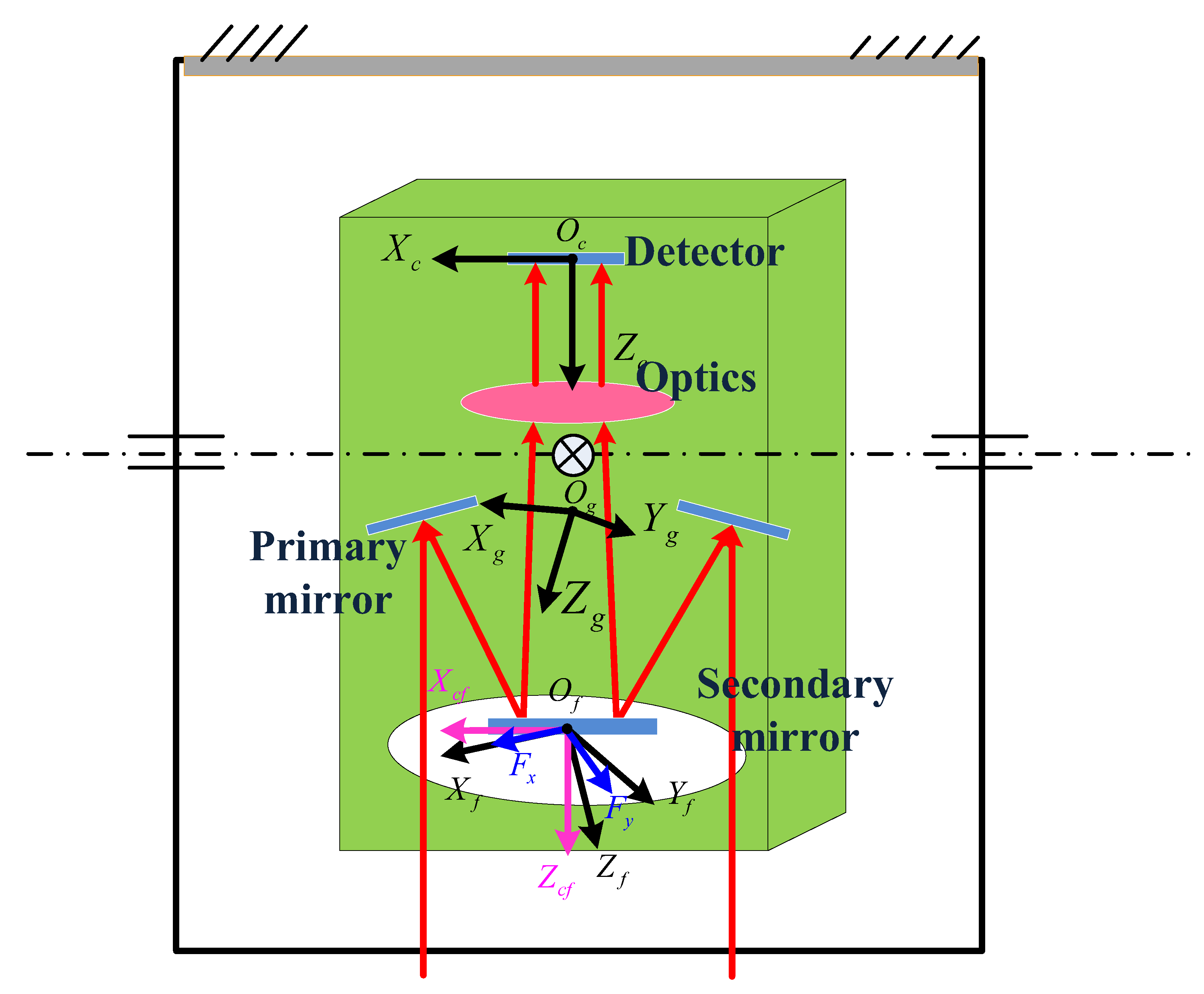
In the process of IMC, the 2D image motion is measured by a two-axis gyro, and compensated for by a secondary mirror which is driven by FSM. To accurately compensate for 2D image motion, the 2D compensating motion of the secondary mirror must be exactly consistent with the direction and magnitude of the 2D image motion. As a result, the axes of the FSM must be parallel to those of the gyro. However, after actual assembly, it is difficult to guarantee their parallel state. In addition, both the two-axis gyroscope and the FSM driver used to measure image motion have orthogonal errors, which will further increase the parallelism error between the axes of FSM and the sensitive axes of the gyro, resulting in errors in the direction of image motion and the second mirror’s compensating motion in the process of dynamic compensation which finally makes the optical coupling phenomenon. Although the secondary mirror has a high efficiency of compensation, it is also sensitive to the optical path, which will amplify the coupling effect and reduce the accuracy of the IMC. To figure out the relationship between the image motion and compensating motion, it is necessary to figure out the relationship between the directions of the FSM driving axes and those of the sensitive axes on the gyro. Since it is hard to directly establish the relationship between the FSM driving axes and the gyro’s sensitive axes, an imaging coordinate system is adopted in this paper as the medium to establish their respective relationships. Thus, the relationship between the FSM driving axes and the gyro’s sensitive axes will be obtained in an indirect way. The following coordinate systems are established.
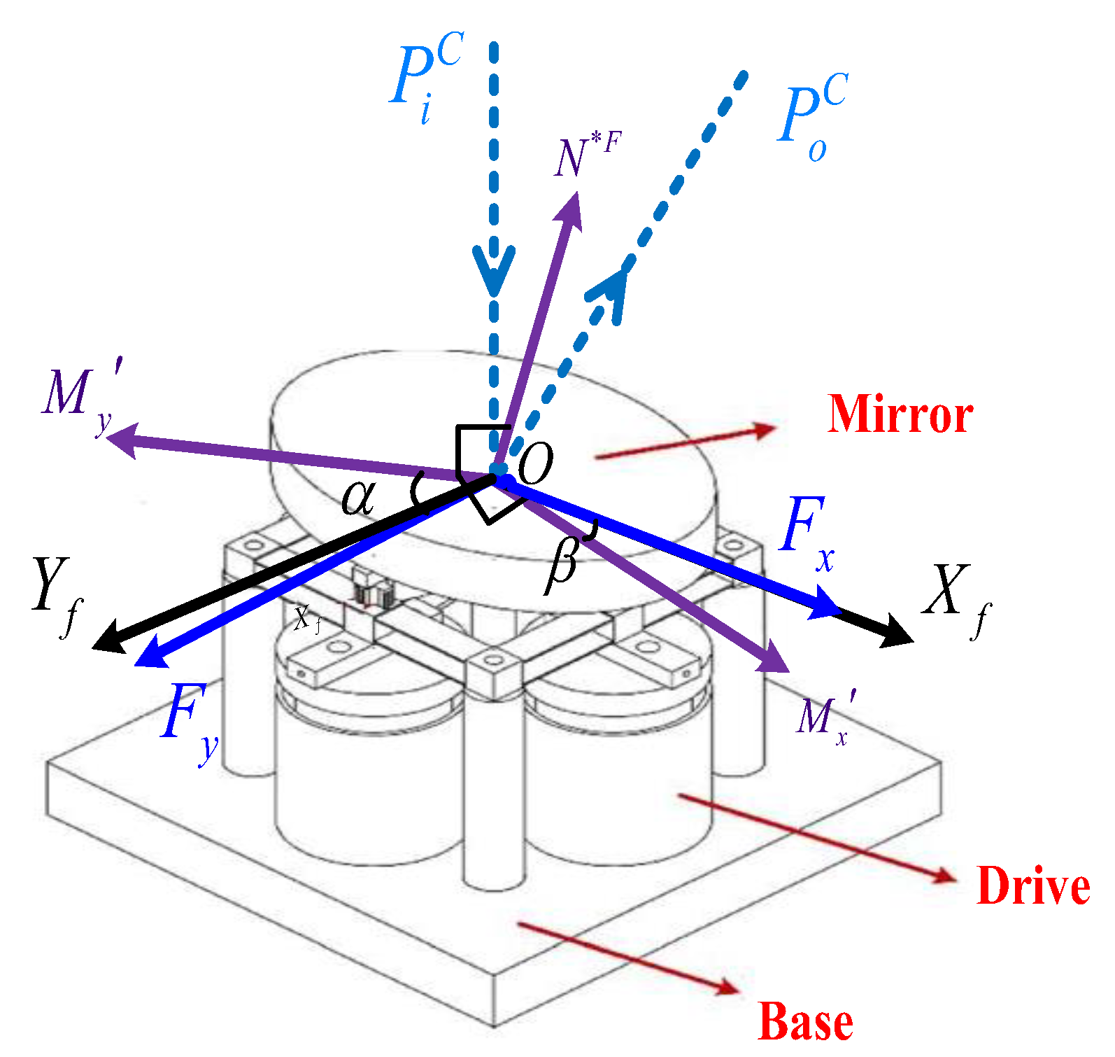
The coordinate system of the secondary mirror (the FSM coordinate system) is denoted as O f - X f Y f Z f . The origin of the coordinate system is O f , which is located at the intersection of the line of sight (LOS) and the secondary mirror. The two rotating axes of FSM, O f F x and O f F y , are located within the plane of O f - X f Y f , where the axes of O F x and O f X f coincide. Considering the orthogonal error of the two driving axes, the angle between the rotating axes O f F y and O f Y f is ξ .
The imaging coordinate system is denoted as O c - X c Y c Z c , with its origin O c located at the intersection of the LOS and the detector. The axis of the Z c lines is along the LOS, pointing to the optical window. The axis of the O c X c lines is along the axis u on the detector. The axis of the O c Y c lines is along the axis v on the detector. The Euler angle of the assembly error between the FSM coordinate system O f - X f Y f Z f and the imaging coordinate system O c - X c Y c Z c is S x , S y   , S z .
The imaging auxiliary coordinate system is denoted as O c f - X c f Y c f Z c f , with its origin O c f coinciding with O f , which is the origin of the FSM coordinate system. The corresponding axes are parallel to the axes of the imaging coordinate system.
The gyro coordinate system is denoted as O g - X g Y g Z g , with its origin O g located at the intersection between the two sensitive axes. The two sensitive axes, G x and G y , are located within the plane of O g - X g Y g , where the axis of G x and the axis of O g X g coincide. Considering the orthogonal error of the two sensitive axes, the angle between the sensitive axes G y and O g Y g is ϵ . The Euler angle of the assembly error between the gyro coordinate system and the imaging coordinate system is G x , G y   , G z . The system of the optical path is shown in Figure 3.
Firstly, the relationship between the direction of the FSM driving axes and those of the imaging coordinate system is analyzed, which is also the relationship between the compensating motion of the secondary mirror and the image motion. The relationships between the FSM rotating axes, FSM coordinate system and imaging auxiliary coordinate system is shown in Figure 4. Selecting vectors M x and M y in the plane where the FSM is located, the plane formed by O f - X f M x is perpendicular to the rotating axis F y , and the plane formed by O f - Y f M y is perpendicular to the rotating axis F x . According to the mechanism of the FSM movement, when the FSM drives the secondary mirror to rotate along axes of α , β , the coordinates of M x , M y in the FSM coordinate system are M x F , M y F , as shown as Equation (1), and its normal vector is N F , shown as Equation (2).
M x F = c o s β 0 s i n β
M y F = c o s ( α ) s i n ( ξ ) c o s ( α ) c o s ( ξ ) s i n ( α )
N F = M y F × M x F = c o s ( α ) s i n ( β ) c o s ( ξ ) cos β sin α + c o s ( α ) s i n ( β ) s i n ( ξ ) c o s ( α ) c o s ( β ) c o s ( ξ )
Since the Euler angle between the FSM coordinate system O f - X f Y f Z f and the imaging coordinate system O C - X c Y c Z c is S x ,   S y   ,   S z , the normal vector in the imaging auxiliary coordinate system is:
N C = L S S x , S y , S z N F
L S S x , S y , S z = c o s S y c o s S z c o s S y s i n S z s i n S y s i n S x s i n S y c o s S z c o s S x s i n S z c o s S x c o s S z + s i n S x s i n S y s i n S z s i n S x c o s S y c o s S x s i n S y c o s S z + s i n S x s i n S z c o s S x s i n S y s i n S z s i n S x c o s S z c o s S x c o s S y
Considering that the assembly-error angle of S x ,   S y   ,   S z is small, and that the higher order infinite minor term can be ignored, it can be simplified as L 1 .
L 1 = 1 S z S y S z 1 S x S y S x 1
N C = L 1 N F
After unifying the unit, it can be expressed as N 1 C .
N 1 C = N C / N C
The function of the secondary mirror is to compose the imaging object and reflector mirror. Based on the law of reflection, the conversion matrix of the incident ray to the emergent ray can be expressed as:
T C = I 2 N 1 C N 1 C = I 2 N C N C N C N C
The main optical ray is:
P i C = 0 0 1
After the secondary mirror motion, the emergent ray is:
P o C = T C P i C = 1 a 1 2 + a 2 2 + a 3 2 2 a 1 a 2 2 a 1 a 3 a 2 2 + a 3 2 a 1 2
where
a 1 = S x   s i n α c o s β + S x   c o s α s i n β s i n ξ + c o s α c o s β c o s ξ + S y   c o s α s i n β c o s ξ
    a 2 = S z   c o s β s i n α + S z   c o s α s i n β s i n ξ c o s α s i n β c o s ξ + S y   c o s α c o s β c o s ξ
a 3 = s i n α c o s β + c o s α s i n β s i n ξ S x   c o s α c o s β c o s ξ + S z   c o s α s i n β c o s ξ
If the angular magnification of the optical system is k , then after the FSM motion, the angle of the emergent ray rotating around the x axis and y axis of the imaging auxiliary coordinate system is σ x , σ y .
  σ x = k P o C y P o C z = k   2 a 1 a 3 a 2 2 + a 3 2 a 1 2 σ y = k P o C x P o C z =   k 2 a 1 a 2 a 2 2 + a 3 2 a 1 2
The relationship between the secondary mirror motion and the compensated image motion can be obtained as
Q x = σ y f = k f 2 a 1 a 2 a 2 2 + a 3 2 a 1 2 Q y = σ x f = k f 2 a 1 a 3 a 2 2 + a 3 2 a 1 2
Substituting Equations (12)–(14) into Equation (16), the following relation will be obtained.
Q x = k f F 1 ( α , β , ξ , S x , S y , S z ) Q y = k f F 2 ( α , β , ξ , S x , S y , S z )
where f is the focal length of the system. From Equation (17), it can be known that F 1 ( α , β , ξ , S x , S y , S z ) and F 2 ( α , β , ξ , S x , S y , S z ) are nonlinear polynomials composed of variables α , β , ξ , S x , S y , S z . It can be seen that there is a coupling relationship between α and β , which are the angles of the 2D FSM motion, and the compensated image motion in the imaging coordinate system. When the FSM rotates around a certain axis, compensated image motion will be generated on both axes, x and y, of the imaging coordinate system. Additionally, since F 1 ( α , β , ξ , S x , S y , S z ) and F 2 ( α , β , ξ , S x , S y , S z ) contain the cross term of the motion angles α , β , the relationship between the FSM rotating angle and the amount of compensated image motion of the corresponding axis in the imaging coordinate system is nonlinear.
Next, the relationship between the direction of the gyro’s sensitive axis and the imaging coordinate system will be analyzed, which is also the relationship between the angular motion sensed by the gyro and the amount of image motion, as shown in Figure 5.
The orthogonal error of the two axes of the gyro, which comprise the angular velocity ω x , ω y that the axes sense, is presented in the gyro coordinate system as ω x ,   ω y .
ω x ω y = ω x + ω y s i n ϵ ω y c o s ϵ
Since the Euler angle of the assembly error between the gyro coordinate system and the imaging coordinate system is G x ,   G y   ,   G z , the angular velocity of the imaging system is ω g x ,   ω g y ,   ω g z .
ω g x ω g y ω g z = L S G x   , G y   , G z ω x ω y 0
Then, the relation between the image motion of Q x ,   Q y and the angular rate is obtained.
Q x Q y = ω g y ω g x   f d t
The following equation can be obtained when substituting Equations (18) and (19) into Equation (20).
ω g y = s i n G x s i n G y c o s G z c o s G x s i n G z ω x + ω y s i n ϵ
+ ω y c o s ϵ c o s G x c o s G z + s i n G x s i n G y s i n G z
ω g x = c o s G y c o s G z ω x + ω y s i n ϵ + ω y c o s G y s i n G z c o s ϵ
It can be seen that there is a coupling relationship between the gyro’s sensitive angular motion, ω x and ω y , and the amount of image motion of the imaging coordinate system. When the gyro only senses the angular motion of the axis ω x , image motion has actually been generated on both axes, x and y, in the imaging coordinate system.

3.2. Modeling

In the existing IMC model, the FSM compensation motion and scanning motion have been added up to determine a synthetic LOS in order to study the stability performance [18,19], without considering the relationship between their motion and that of the image motion. In order to analyze the IMC accurately, based on the coarse–fine composite model, and considering the coupling relationship between 2D scanning motion, 2D secondary mirror compensating motion and image motion, a complete 2D image-motion model is established as shown in Figure 6, with image motion as the controlled variable. The blue box in the diagram shows the 2D coarse scanning platform model [20,21]. The green box shows the FSM model [22,23]. The orange box shows the optical coupling model, describing the relationship between 2D platform motion, FSM motion and image motion.

4. A Multilevel 2D IMC Method

In order to solve the problem of optical path coupling in the process of 2D IMC, this paper adopts the method of optical path decoupling, and designs a correction regulator of the optical path decoupling, on the basis of coarse and fine IMC. The regulator is located outside the coarse and fine control loop for decoupling correction. Since there have been many research efforts on coarse–fine inner loop control methods [24,25,26,27], this paper focuses on the design of the ODCR. This paper also presents the synthesis method, which is designed to control the instructions of the coarse–fine outer loop in the 2D IMC system.

4.1. Control of the Coarse Loop

In wide-field imaging, POS is supposed to measure the position and attitude of the base of the coarse scanning platform, including yaw angle φ , pitch angle θ , roll angle , flight velocity vector V A C / E F N and height H. The velocity V 1 along the flight direction and the velocity V 2 along the wingspan direction are calculated from the flight velocity vector V A C / E F N and the yaw attitude angle φ .
V 1 V 2 V 3 = c o s φ s i n φ 0 s i n φ c o s φ 0 0 0 1 V A C / E F N
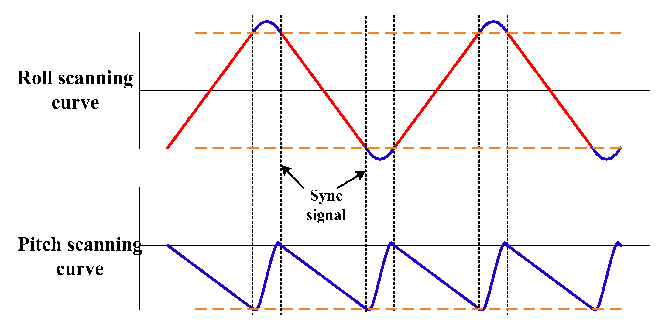
The control loop of the coarse roll scanning gimbal uses the roll angular velocity component, ω r _ f d b , which is sensed by the gyro, as the speed feedback. For each scanning strip, the way to synthesize the roll scanning speed command, ω r _ c o m , is presented as
ω r _ c o m = F O V 0.15 T + ω r 0
The ω r _ c o m is the roll scanning curve shown in Figure 7. In Equation (24), FOV is the expected scanning field-of-view angle. T is the strip scanning period, and γ h is the view angle of a single frame of the camera in the flight direction which satisfies the following condition:
T × v = H × tan γ h 2 × ( 1 o v e r l a p )
In Equation (24), ω r 0 is the image motion of the flight motion in the scanning direction, which can be described as:
ω r 0 = τ V 2 H
where τ can be denoted as
τ =   c o s (   θ + e n c o d e _ θ e n c o d e _ θ 0 )     c o s ( + e n c o d e _ e n c o d e _ 0 )
In Equation (27), e n c o d e _ and e n c o d e _ θ are the two angles measured by the roll and the pitch encoders, respectively. When the roll attitude angle and the pitch attitude angle θ of the base are both at 0°, and the LOS is perpendicular to the ground, the angular values measured by the encoder are e n c o d e _ 0 and e n c o d e _ θ 0 .
The control loop of the coarse pitch scanning gimbal uses the pitch angular velocity component, ω p _ f d b , which is sensed by the gyro, as the speed feedback. For each scanning strip, the way to synthesize the pitch scanning speed command, ω p _ c o m , is presented as Equation (28). The ω p _ c o m is the pitch scanning curve shown in Figure 7.
ω p _ c o m = τ V 1 H

4.2. Control of the Fine Loop

  • General fine FSM control
When the coarse scanning gimbal moves to a certain exposure position, the FSM fine pitch velocity ω p will be synthesized by removing the forward image motion component generated by flight from the pitch angular velocity component ω p _ f d b sensed by the gyro. The position command θ f s m _ p _ c o m will be integrated from ω p . According to this command, the FSM rotates in the opposite direction around the pitch axis to realize the forward image motion and the disturbance compensation in the pitch direction.
ω p = ω p _ f d b ω p _ c o m
θ f s m _ p _ c o m = 0 t ω p 2 k d t
The FSM fine roll velocity ω r will be synthesized by removing the image motion component generated by the flight motion in the scanning direction from the roll angular velocity component ω r _ f d b sensed by the gyro. The position command θ f s m _ r _ c o m will be integrated from ω r . According to this command, the FSM rotates in the opposite direction around the roll axis to realize the scanning IMC and the precision stability in the roll direction.
ω r = ω r _ f d b ω r 0
θ f s m _ r _ c o m = k 0 t ω r _ f d b ω r 0 2 k d t
b.
Fine control with ODCR
The conventional fine control method does not take the influence of optical coupling into consideration. In order to solve this problem, this paper defines a correction regulator of optical coupling in a fine control loop. The image motion amount of Q x ,   Q y , corresponding to the sensitive angular velocity of the two-axis gyro, is obtained by substituting Equations (21) and (22) into Equation (20). The image motion is completely compensated for by the 2D motion of the secondary mirror, so the 2D motion of the secondary mirror needs to compensate for the image motion amount Q x ,   Q y as follows.
Q x Q y = Q x Q y = ω g y ω g x   f d t
According to Equation (3), which shows the relationship between the secondary mirror motion and the compensated image motion, the coordinates of the emergent ray in the imaging auxiliary coordinate system after the 2D secondary mirror compensating motion satisfy the condition
P o C x P o C z = σ y * k = Q x /   k f P o C y P o C z = σ x * k = Q y / k f
It can then be deduced that, after FSM compensating motion, the desired emergent ray coordinates in the imaging auxiliary coordinate system are P o C .
P o C = Q x Q y k f
Since the incident ray, the emergent ray and the normal vector are coplanar, and the angle between the normal vector and the incident ray is equal to the angle between the emergent ray, the expected coordinates of the normal vector after FSM compensating motion in the imaging auxiliary system can be obtained as follows.
N * C = 1 2 P i C + Q x Q y k f / σ x * 2 + σ y * 2 + k
The expected coordinates of the normal vector in the FSM coordinate system are obtained from the relationship between the imaging auxiliary coordinate system and the FSM coordinate system.
N * F = L 1 1 N C =   1 2 Q x 2 + Q y 2 + k 2 f 2   Q x + S y Q x 2 + Q y 2 + k 2 f 2   + k   f S z Q y Q y S x Q x 2 + Q y 2 + k 2 f 2   + k   f + S z Q x k f + S x Q y S y Q x + Q x 2 + Q y 2 + k 2 f 2    
The plane where the secondary mirror is located after FSM motion can be determined according to the normal vector. Taking the voice coil FSM as an example, its typical structure diagram [28] is as follows. When taking two vectors M x and M y in the secondary mirror plane, then the plane of O f - X f M x is perpendicular to the rotating axis of F y , and the plane of O f - Y f M y is perpendicular to the rotating axis of F x . In addition, since both M x and M y are perpendicular to the normal vector N * F , it can be deducted that M x F y and M x N * F ; similarly, M y F x and M y N * F . The relationship between the FSM angle and the secondary mirror plane shown in Figure 8. Therefore, the coordinates of M x and M y after FSM motion can be deduced as follows.
M x = N * F × O F y = N * F × s i n ξ c o s ξ 0
M y = O F x × N * F = 1 0 0 × N * F
Then, the roll and pitch FSM instruction angles α and β after decoupling can be deduced as follows.
α = aco s F y M y                   M x z > 0 acos F y M y       M x z < 0
β = acos F x M x                   M x y < 0 acos F x M x       M x y > 0

5. Experiments

5.1. Calibration Tests on Optical Coupling

To figure out the relationship between the 2D image motion and the compensation motion, the calibration between the FSM driving axis and imaging coordinate system, and the calibration between the gyro’s sensitive axis and imaging coordinate system should be conducted, respectively. The calibration experiment of optical coupling is shown in Figure 9.
(a)
Calibration of the FSM driving axes and the imaging coordinate system
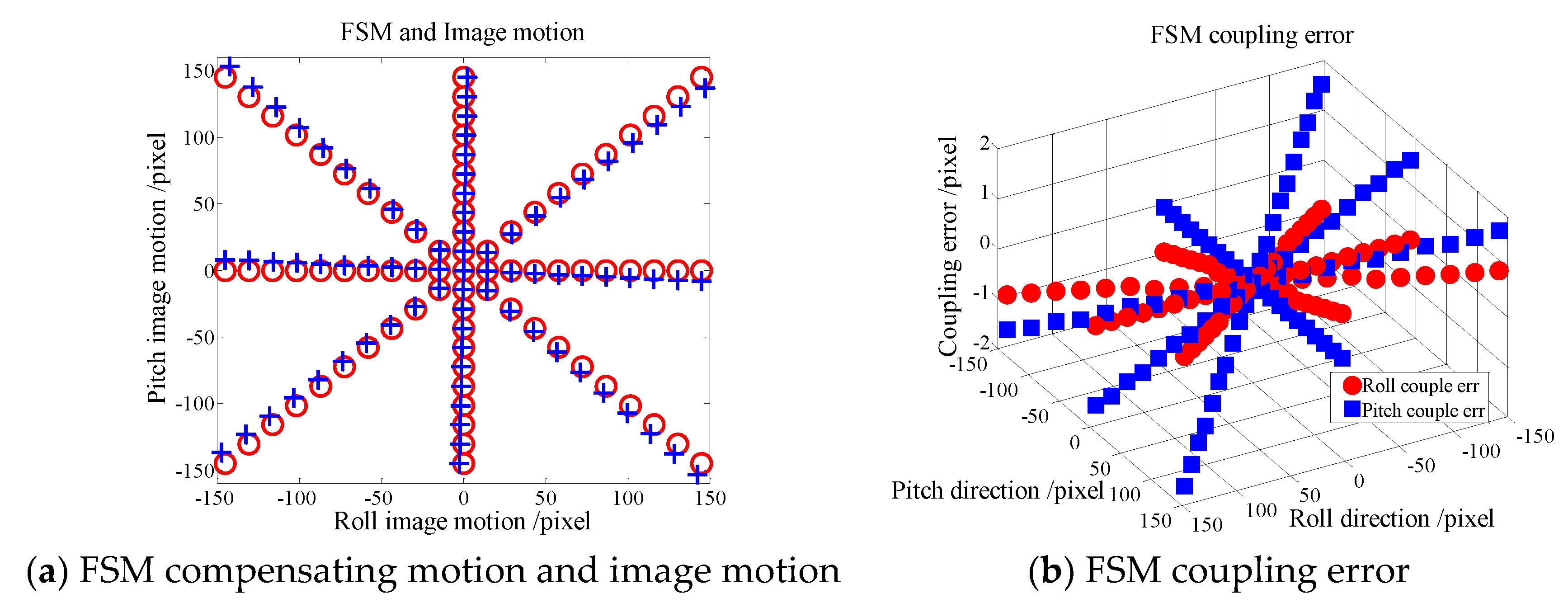
The two-axis angle of FSM is set at zero, and the pointing angle of the 2D scanning platform is adjusted so that the cross target is in the center of the image coordinate system. The 2D scanning platform is kept at this position. The two axes of the FSM are driven to move in a unit of 200 urad in the shape of “*” and within a range of ±2 mrad to compensate for the image motion. At each calibrated point, the image is stored, and the position of the cross target in the image is thereby obtained. The relationship between FSM compensating motion and image motion is shown in Figure 10a. In the figure, the red “○” represents the image motion corresponding to the FSM motion when no light paths couple in theory, which is also when the FSM axes are parallel to the imaging coordinate systems of O c X c and O c Y c . The blue “+” represents the image motion generated by the FSM motion in practice. Figure 10b shows the errors of the FSM at different calibrated points corresponding to Figure 10a, with the red ● showing the coupling error in the roll direction, while the blue ■ shows the coupling error in the pitch direction.
It can be seen that, due to the orthogonal error of the FSM and the assembly error between the FSM and the imaging detector, the moving direction of the FSM is inconsistent with the image motion direction in the imaging coordinate system. Therefore, there exists a coupling effect. When the FSM moves around one axis, coupled image motion has occurred on the other axis. The amounts of coupled image motions are different at each position. It can be seen from the coupling error that the maximum amount of the coupled image motion is 1.6 pixels when the FSM rolling motion is coupled with the pitch motion and 0.9 pixels when the FSM pitch motion is coupled with the rolling motion. At the same time, the compensated image motion amount generated by the FSM two-axis motion without assembly coupling error between FSM and imaging detector in theory is inconsistent with that found in practice. The calibrated data in Figure 10a was optimized by the least square method [29,30,31,32], and the parameters of the FSM coordinate system and imaging coordinate system are calculated in Table 1.
(b)
Calibration of the direction of gyro axes and the imaging system
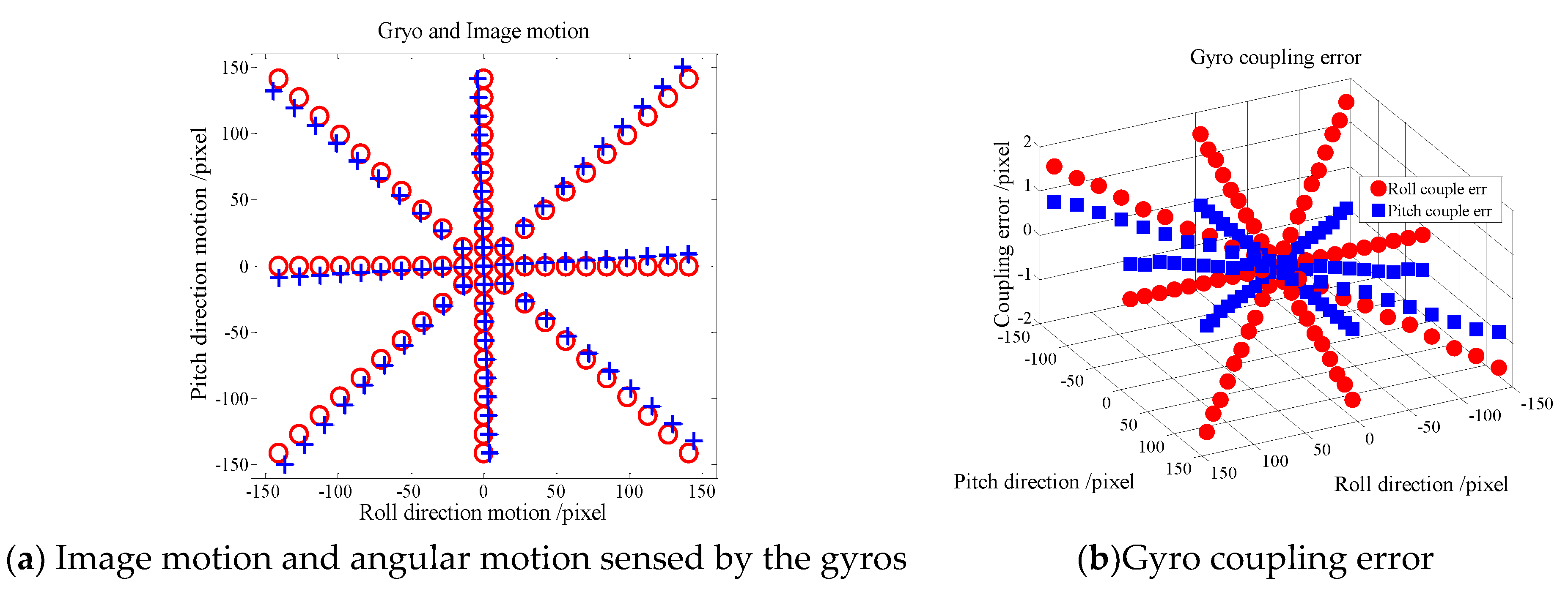
When the two-axis angle of FSM is set at zero, the pointing angle of the 2D scanning platform is adjusted so that the cross target is in the center of the image coordinate system. Starting from the current position, the 2D scanning platform is driven by the gyro as a feedback to move in a unit of 200 urad in the shape of “*” within a range of ±2 mrad. Similarly, at each calibrated point, the image is stored to obtain the position of the cross target in the image. The relationship between the angle sensed by the gyros and the image motion is shown in Figure 11a. In the figure, the red “○” represents the image motion corresponding to the angular motion sensed by the gyros when no light paths couple in theory, which is also when the two sensitive axes are parallel to the imaging coordinate systems of O c X c and O c Y c . The blue “+” represents the image motion sensed by the gyro. Figure 11b shows the errors of the gyro at different calibrated points corresponding to Figure 11a, with the red ● showing the roll coupling error while the blue ■ shows the pitch coupling error.
It can be seen that, due to the orthogonal error of the gyro and the assembly error between the gyro and the imaging detector, the directions of the gyro’s sensitive axes are inconsistent with directions O c X c and O c Y c of the imaging coordinate systems. Therefore, there exists another coupling effect. When the gyro senses motion only in the roll direction, it can be seen from the calibrated data that the image motion has occurred not only in the roll direction of the imaging coordinate system, but also in the pitch direction. It can be known from the coupling error that the maximum amount of the coupled image motion in the pitch direction is 0.8 pixels. Similarly, when the gyro senses motion only in the pitch direction, the image motion has occurred not only in the pitch direction, but also in the roll direction. The maximum amount of coupled image motion in the roll direction is 1.8 pixels. In the meantime, the amount of image motion sensed by the gyro when there is no optical coupling in theory is also inconsistent with that found in practice. Similarly, the calibration data in Figure 11a are optimized by the least square method, and the parameters of the gyro coordinate system and the imaging coordinate system are obtained, as shown in Table 2.
By substituting S x   , S y   , S z , G x   , G y   , G z , ξ , ϵ , which are the calibrated results, into Equations (37)–(41), the ODCR will be obtained.

5.2. Tests on the 2D IMC in the Laboratory

Firstly, a test on the 2D IMC is carried out in the laboratory. The pixel size of the camera detector is 6.4 um, the focal length is 451.2 mm and the exposure time is set to 2 ms. In order to quantitatively analyze the effect of the 2D IMC, a cross target is used as the target. The focal length of the collimator is 3 m, and the line-width of the target is 0.05 mm. Without considering the dispersion effect, it can be calculated that the cross of the target takes up one pixel in the image. But in fact, there exists a dispersion effect, and from the pixel enlargement, the cross target will be dispersed into three pixels. The following three conditions are tested.
(a)
The rolling speed of the 2D scanning platform is set at +60°/s, with stable inertia in the pitch direction. A 1D IMC test is conducted by simulating the scanning image motion of an actual flight, without adopting the ODCR.
(b)
The rolling speed of the 2D scanning platform is set at +60°/s, with a pitch scanning speed of 5°/s. A 2D IMC test is conducted by simulating the scanning image motion and forward image motion of an actual flight, without adopting the ODCR.
(c)
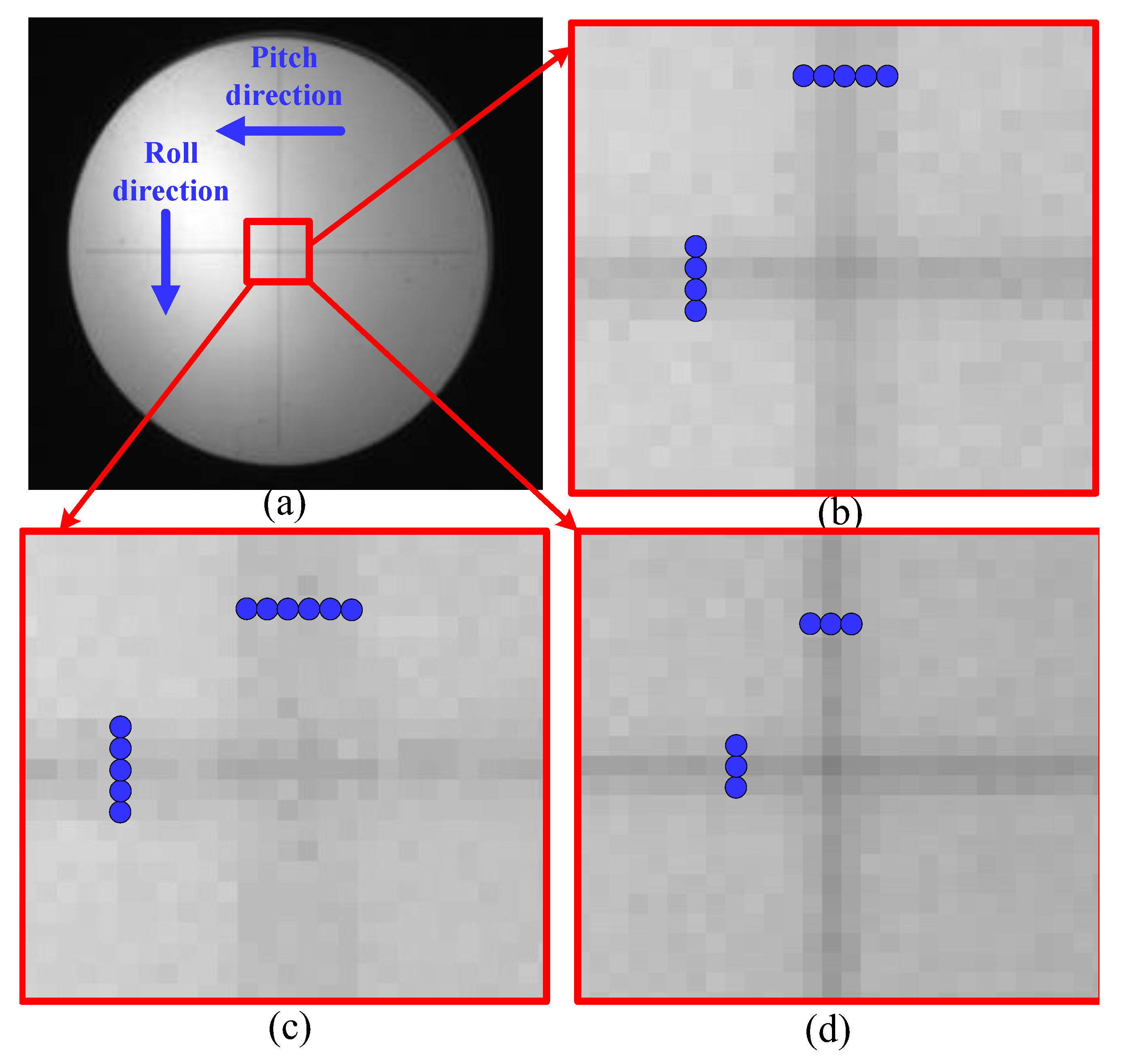
The rolling speed of the 2D scanning platform is set at +60°/s, with a pitch scanning speed of 5°/s. A 2D IMC test is conducted by simulating the scanning image motion and forward image motion of an actual flight. This time, the 2D IMC test is carried out by adopting ODCR. The results are shown in Figure 12.
The analyses of the test results are as follows. Condition (a) is a 1D IMC test. The cross-target image is enlarged after 1D IMC, as shown in Figure 12b. It can be seen from the pixel enlargement that the cross target has a dispersion of 4 pixels in the roll direction and 5 pixels in the pitch direction. If the dispersion effect on both sides of the cross target in the pixel enlargement is ignored, then the IMC error of the 1D compensation method without ODCR is nearly 2 pixels in the roll direction and 3 pixels in the pitch direction. This is because the direction of the FSM compensation motion is inconsistent with that of the image motion. In the process of the 1D compensation motion in the roll direction, there is a component in the pitch direction, so an image motion of 3 pixels is coupled in the pitch direction. In addition, due to the inconsistency between the amounts of the actual compensated image motion generated by FSM and the theoretical image motion, full compensation in the roll direction cannot be realized, resulting in a residual image motion of 2 pixels in the roll direction.
Condition (b) is a 2D IMC test without decoupling. From the enlargement of the cross target as shown in Figure 12c, it can be seen that the cross target has a dispersion of 5 pixels in the roll direction and 6 pixels in the pitch direction. Ignoring the dispersion effect on both sides of the cross target in the pixel enlargement, it can be seen that the compensation error of the conventional 2D compensation method is nearly 3 pixels in the roll direction and 4 pixels in the pitch direction. As opposed to Condition (a), compensating motion in the pitch direction is introduced in Condition (b). Since the direction of the FSM compensation motion is inconsistent with that of the image motion, the pitch motion further amplifies the coupling effect, causing the accuracy error to increase by up to 3 pixels in the roll direction. In addition, due to the inconsistency between the amounts of the actual compensated image motion generated by FSM and the theoretical image motion, full compensation in the pitch direction cannot be realized, causing the error to increase by up to 4 pixels in the pitch direction, as compared with Condition (a).
Condition (c) is a 2D IMC test with ODCR. From the enlargement of the cross target as shown in Figure 12d, it can be seen that the cross target has a dispersion of 3 pixels, both in the roll direction and the pitch direction. Ignoring the dispersion effect, it can be seen that the compensation accuracy is nearly 1 pixel in both directions. Compared with Conditions (a) and (b), the 2D IMC method proposed in this paper by adopting ODCR effectively solves the optical path coupling problem of the inconsistencies in direction and size between the FSM compensation motion and the image motion. As a result, the accuracy of the 2D IMC reaches 1 pixel.
In the cross-target test, the accuracy of the IMC can be apparently read from the pixel enlargement figure. To quantify the accuracy of the image motion, an indirect method of the modulation transfer function (MTF) [33,34,35] is adopted. For the wide-field imaging system, the MTF of   M , M s t i l l and M m o t i o n satisfies the following relationship [36,37,38] shown in Equation (42).
M = M s t i l l × M m o t i o n
In Equation (42), the M is the total MTF when the system operates in scanning–imaging mode. The M s t i l l is the MTF when the gimbal stops scanning and is still imaging. The M m o t i o n is the reduction factor caused by motion. According to [36,37,38], we can obtain the relationship between M m o t i o n and the amount of image motion.
M m o t i o n = s i n c ( ρ f ε ) = s i n ( π ρ f ε ) π ρ f ε
In Equation (43), ρ f is the spatial frequency, set as 0.1 lp/pix, and ε is the residual motion after image motion compensation, i.e., IMC error. According to Equations (42) and (43), if we can obtain M and M m o t i o n , then we can calculate the amount of image motion compensation.
Replacing the cross target in the optical collimator with the knife-edge target, the MTF of M s t i l l for the roll direction and pitch direction is measured when the scanning gimbal and the FSM are both still. Similarly, when the system scans and operates according to the above three conditions, (a), (b) and (c), we can measure the total MTF of M for the roll direction and pitch direction corresponding to the three conditions. We have conducted 20 tests in each condition to calculate the root mean square of M and M m o t i o n .
Substituting the root mean square of M and M m o t i o n under each operating condition into Equations (42) and (43), the root mean square of IMC error can be calculated as follows in Table 3.
It can be seen from Table 3 that the results for MTF measured indirectly are equivalent to the directly interpreted results of the cross target. In the 1D compensation method without ODCR, the compensation error is 1.83 pixels in the roll direction and 2.67 pixels in the pitch direction. In the 2D compensation method without ODCR, where the coupling effect of optical path is further increased, the compensation error is 2.91 pixels in the roll direction and 3.73 pixels in the pitch direction. In the 2D compensation method with ODCR presented in this paper, which effectively solves the problem of optical coupling, the compensation error is 0.46 pixels (RMS) in the roll direction, and 0.57 pixels (RMS) in the pitch direction at the scanning speed of 60°/s. This method is suitable for 2D IMC applications and can increase the scanning speed to 60°/s, while the compensation error meets the requirements for the imaging quality.

5.3. Flight Test

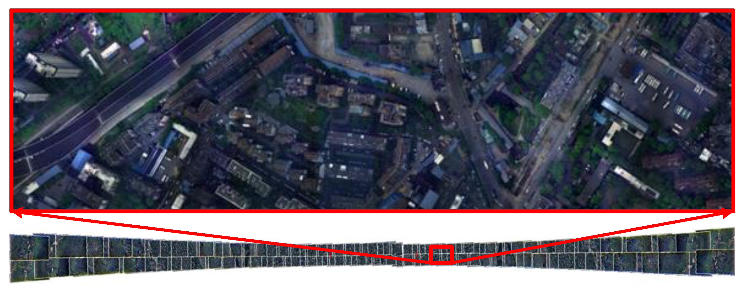
In the flight test based on the 2D compensation method without ODCR, where the flight height is 3.5 km, wide-field images are taken by two-way scanning. When the exposure time is 2 ms, the scanning speed is 60°/s, and the imaging width is 3.5 times the flight height (the scanning FOV is 120°), the scanning cycle of each strip takes only 2.5 s and a clear strip chart is shown in Figure 13.
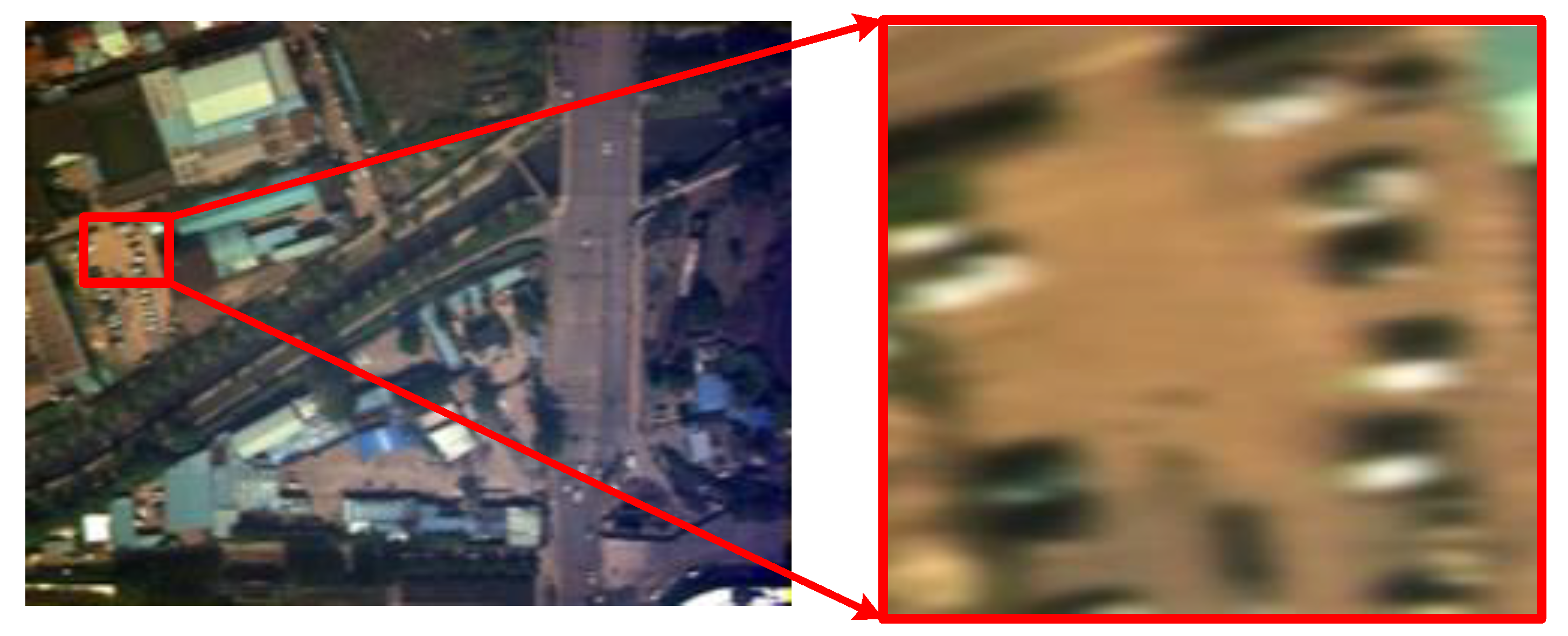
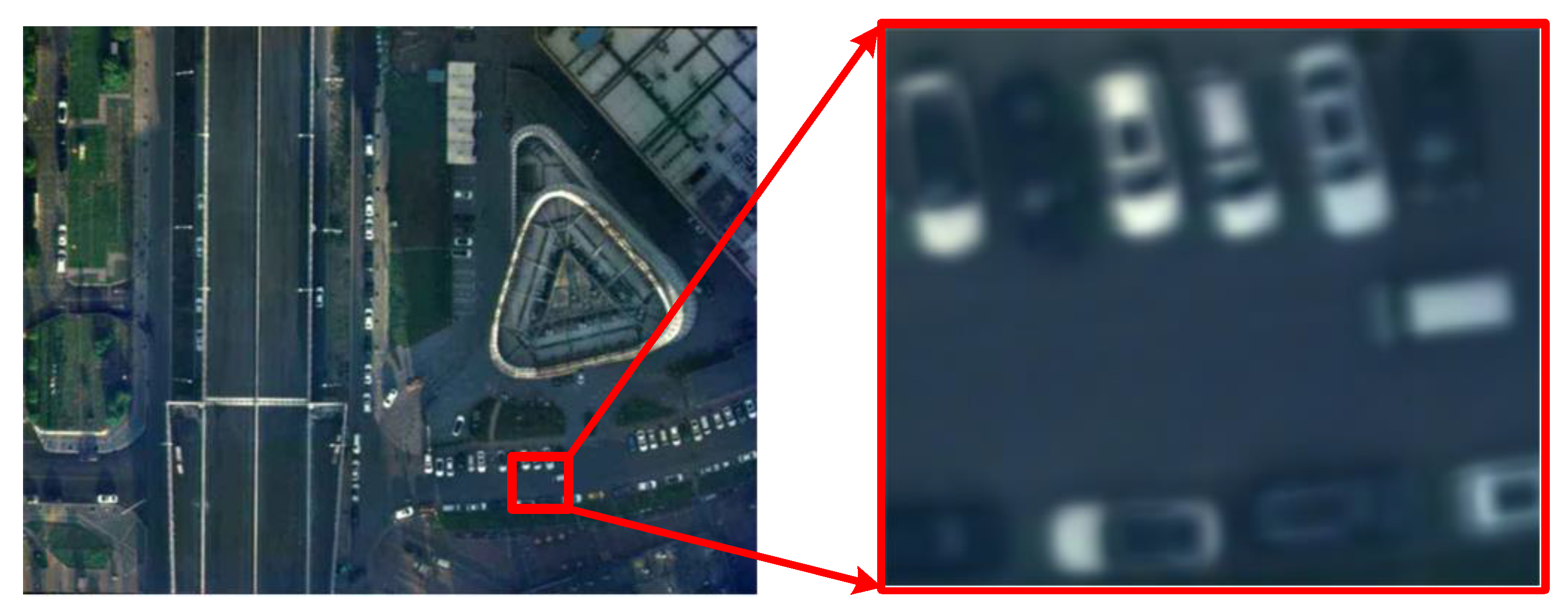
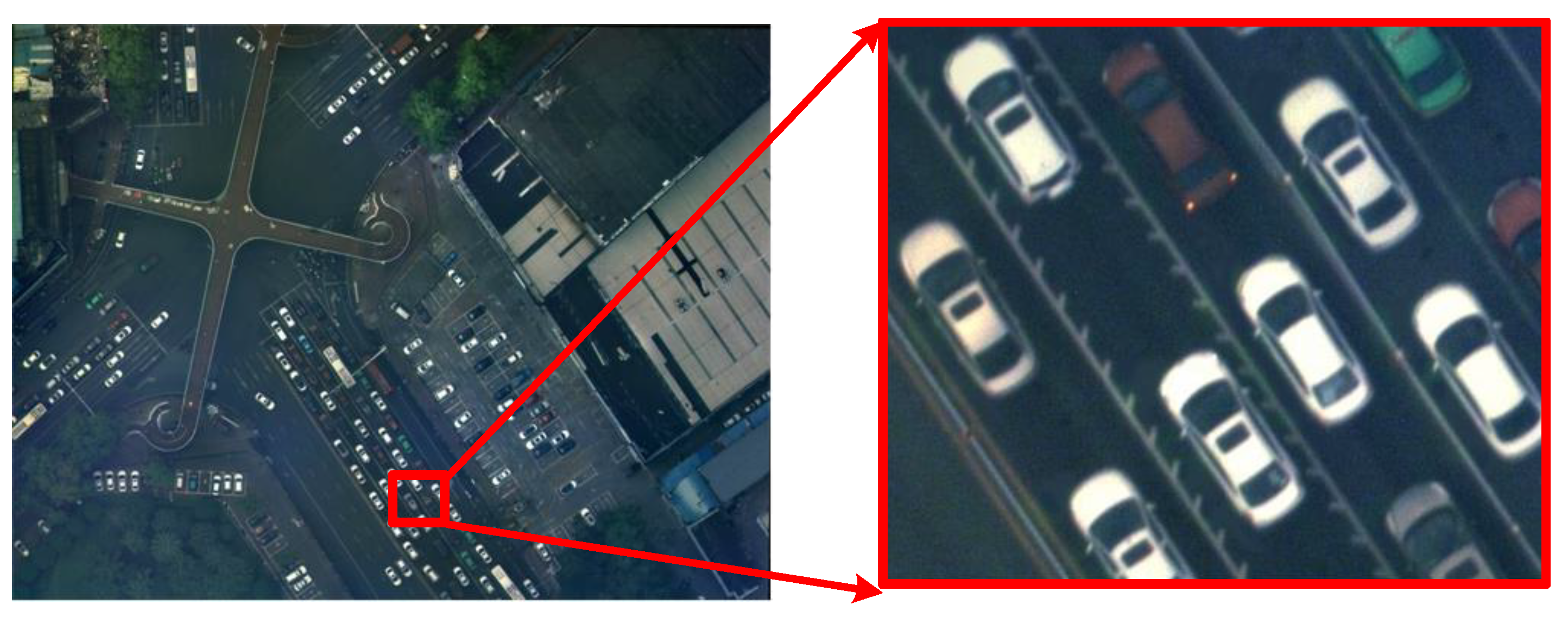
During the flight, a comparison is made between the method with the IMC turned off, the general 2D IMC method, and the method with ODCR. The results are shown in Figure 14, Figure 15 and Figure 16. It can be seen that the image taken when the IMC function is turned off is blurred, and the outline of the car cannot be distinguished. When using the conventional IMC method, the edge of the image still has a fuzzy effect, which makes it difficult to distinguish the rear-view mirror of the car. When using the IMC method presented in this paper, the rear-view mirror of the car can be clearly distinguished.

6. Conclusions

This paper presents a highly integrated 2D IMC method for the wide-field camera. To solve the optical coupling problem, the coupling relation of optical paths in a 2D IMC process is deduced and analyzed. A complete 2D IMC model is established, and a 2D IMC method including ODCR is designed. This method is verified in laboratory and field flight tests. The results show that the proposed method can effectively correct the coupling errors of the optical path and achieve high precision in IMC. When the scanning speed is 60°/s and the exposure time is 2ms, the accuracy of the 2D IMC is up to 0.46 pixels (RMS) in the roll direction and 0.57 pixels (RMS) in the pitch direction. This method is suitable for 2D IMC applications and can increase the scanning speed to 60°/s, while the compensation error meets the requirements for the imaging quality. This research can provide a reference for the research of multidimensional IMC in wide-field-measuring cameras.

Author Contributions

Conceptualization, S.C.; methodology, S.C.; software, S.C., W.C. and C.M.; validation, S.C., X.L. and W.C.; writing—original draft preparation, S.C.; writing—review and editing, S.C. and H.Z.; supervision, J.C. All authors have read and agreed to the published version of the manuscript.

Funding

This research received no external funding.

Institutional Review Board Statement

Not applicable.

Informed Consent Statement

Not applicable.

Data Availability Statement

The data presented in this study are available from the first author or the corresponding author upon reasonable request.

Conflicts of Interest

The authors declare no conflict of interest.

References

  1. Yang, J.; Schonfeld, D.; Mohamed, M. Robust video stabilization based on particle filter tracking of projected camera motion. IEEE Trans. Circuits Syst. Video Technol. 2009, 19, 945–954. [Google Scholar] [CrossRef]
  2. Sweeney, M.N.; Erdelyi, E.; Ketabchi, M.; Kent, B. Design considerations for optical pointing and scanning mechanisms. Proc. SPIE Optomech. 2003, 5176, 135–146. [Google Scholar]
  3. Gorin, B.A. Side oblique real-time orthophotography with the 9Kx9K digital framing camera. In Proceedings of the Society of Photo-Optical Instrumentation Engineers Conference on Airborne Reconnaissance, Orlando, FL, USA, 8 August 2003. [Google Scholar]
  4. Benzarti, F.; Amiri, H. Repairing and Inpainting Damaged Images using Diffusion Tensor. arXiv 2013, arXiv:1305.2221. [Google Scholar]
  5. Pratlong, J.A.; Jerrama, P.; Tsiolisa, G. TDI-CMOS Image Sensor for Earth Observation. Sens. Syst. Next-Gener. Satell. 2018. [Google Scholar] [CrossRef]
  6. Xu, J.; Shi, X.; Nie, K.; Gao, Z. A Global Shutter High Speed TDI CMOS Image Sensor with Pipelined Charge Transfer Pixel. IEEE Sens. J. 2018, 18, 2729–2736. [Google Scholar] [CrossRef]
  7. Zhang, J.; Ding, Y.; Zhang, L.; Tian, H.; Yuan, G. Precise alignment method of time-delayed integration charge-coupled device charge shifting direction in aerial panoramic camera. Opt. Eng. 2016, 55, 125101. [Google Scholar] [CrossRef]
  8. Wang, D.; Li, W.; Yao, Y.; Huang, H.; Wang, Y. A fine IMC method for the panoramic TDI CCD camera in remote sensing applications. Opt. Commun. 2013, 298–299, 79–82. [Google Scholar]
  9. Lv, T.; Ruan, P.; Jiang, K.; Jing, F. Modeling and analysis of fast steering mirror disturbance effects on the line of sight jitter for precision pointing and tracking system. Mech. Syst. Signal Process. 2023, 188, 110002. [Google Scholar] [CrossRef]
  10. Alvi, B.A.; Asif, M.; Siddiqui, F.A.; Safwan, M.; Bhatti, J.A. Fast Steering Mirror Control Using Embedded Self-Learning Fuzzy Controller for Free Space Optical Communication. Wirel. Pers. Commun. 2014, 76, 643–656. [Google Scholar] [CrossRef]
  11. Cho, M.; Corredor, A.; Dribusch, C.; Park, W.H.; Sheehan, M.; Johns, M.; Shectman, S.; Kern, J.; Hull, C.; Kim, Y.S. Performance prediction of the fast steering secondary mirror for the Giant Magellan Telescope. Proc. SPIE-Int. Soc. Opt. Eng. 2012, 8444, 24. [Google Scholar] [CrossRef]
  12. Hayakawa, T.; Watanabe, T.; Ishikawa, M. Real-time high-speed motion blur compensation system based on back-and-forth motion control of galvanometer mirror. Opt. Express 2015, 23, 31648–31661. [Google Scholar] [CrossRef] [PubMed]
  13. Yang, Y.; Yu, C.; Wang, Y.; Hua, N.; Kuang, H. Imaging attitude control and IMC residual analysis based on a three-axis inertially stabilized platform. Appl. Sci. 2021, 11, 5856. [Google Scholar] [CrossRef]
  14. Wang, L.; Liu, X.; Wang, C. Modeling and design of fast steering mirror in IMC for backscanning step and stare imaging systems. Opt. Eng. 2019, 58, 1. [Google Scholar]
  15. Xiu, J.; Huang, P.; Li, J.; Zhang, H.; Li, Y. Line of Sight and Image Motion Compensation for Step and Stare Imaging System. Appl. Sci. 2020, 10, 7119. [Google Scholar] [CrossRef]
  16. Yuquan, Z. Conceptual Design and IMC Rate Analysis of Two-Axis Fast Steering Mirror for Dynamic Scan and Stare Imaging System. Sensors 2021, 21, 6441. [Google Scholar]
  17. Chang, T.; Wang, Q.; Zhang, L.; Hao, N.; Dai, W. Battlefield dynamic scanning and staring imaging system based on fast steering mirror. J. Syst. Eng. Electron. 2019, 30, 37–56. [Google Scholar]
  18. Sun, C.S.; Ding, Y.L.; Wang, D.J.; Tian, D.P. Backscanning step and stare imaging system with high frame rate and wide coverage. Appl. Opt. 2015, 54, 4960–4965. [Google Scholar] [CrossRef]
  19. Held, K.J.; Robinson, B.H. TIER II Plus airborne EO sensor LOS control and image geolocation. IEEE Aerosp. Conf. 1997, 2, 377–405. [Google Scholar]
  20. Hilkert, J.M. Inertially stabilized platform technology. IEEE Control. Syst. Mag. 2008, 28, 26–46. [Google Scholar]
  21. Ahi, B.; Nobakhti, A. Hardware implementation of an ADRC controller on a gimbal mechanism. IEEE Trans. Control. Syst. Technol. 2018, 26, 2268–2275. [Google Scholar] [CrossRef]
  22. Csencsics, E.; Schlarp, J.; Schopf, T.; Schitter, G. Compact high performance hybrid reluctance actuated fast steering mirror system. Mechatronics 2019, 62, 102251. [Google Scholar] [CrossRef]
  23. Wang, Z.; Zhang, B.; Li, X.; Zhang, S. Study on application of model reference adaptive control in fast steering mirror system. Opt. -Int. J. Light Electron Opt. 2018, 172, 995–1002. [Google Scholar] [CrossRef]
  24. Hilkert, J.M.; Pautler, B. A reduced-order disturbance observer applied to inertially stabilized line-of-sight control. Proc. SPIE-Int. Soc. Opt. Eng. 2011, 8052, 12. [Google Scholar]
  25. Tian, D.; Xu, R.; Sariyildiz, E.; Gao, H. An Adaptive Switching-Gain Sliding-Mode-Assisted Disturbance Observer for High-Precision Servo Control. IEEE Trans. Ind. Electron. 2022, 69, 1762–1772. [Google Scholar] [CrossRef]
  26. Emre, S.; Oboe, R.; Ohnishi, K. Disturbance Observer-Based Robust Control and Its Applications: 35th Anniversary Overview. IEEE Trans. Ind. Electron. 2019, 99, 1. [Google Scholar]
  27. Ran, B.; Wen, L.; Zhu, L.; Yang, K.; Yang, P.; Du, R.; Wang, S.; Xu, B. Coupled dynamic reaction force study of a large-aperture piezoelectric fast steering mirror. Appl. Opt. 2021, 60, 3393–3402. [Google Scholar] [CrossRef] [PubMed]
  28. Chen, G.; Liu, P.; Ding, H. Structural parameter design method for a fast-steering mirror based on a closed-loop bandwidth. Front. Mech. Eng. 2020, 15, 11. [Google Scholar] [CrossRef]
  29. Yuan, D.; Ding, Y.; Yuan, G.; Li, F.; Zhang, L. Two-Step Calibration Method for Extrinsic Parameters of an Airborne Camera. Appl. Opt. 2021, 60, 1387–1398. [Google Scholar] [CrossRef]
  30. Li, J.; Liu, Z. Camera geometric calibration using dynamic single pixel illumination with deep learning networks. IEEE Trans. Circuits Syst. Video Technol. 2020, 30, 2550–2558. [Google Scholar] [CrossRef]
  31. Yin, L.; Wang, X.; Ni, Y.; Zhou, K.; Zhang, J. Extrinsic parameters calibration method of cameras with non-overlapping fields of view in airborne remote sensing. Remote Sens. 2018, 10, 1298. [Google Scholar] [CrossRef]
  32. Deng, L.; Lu, G.; Shao, Y.; Fei, M.; Hu, H. A novel camera calibration technique based on differential evolution particle swarm optimization algorithm. Neurocomputing 2016, 174, 456–465. [Google Scholar] [CrossRef]
  33. Djite, I.; Estribeau, M.; Magnan, P.; Rolland, G.; Petit, S.; Saint-Pe, O. Theoretical Models of Modulation Transfer Function, Quantum Efficiency, and Crosstalk for CCD and CMOS Image Sensors. IEEE Trans. Electron Devices 2012, 59, 729–737. [Google Scholar] [CrossRef]
  34. Bian, J.; Ma, D.M.; Sun, G.; Shao, J. MTF test technology analysis of infrared electro-optical imaging system. J. Appl. Opt. 2013, 34, 748–753. [Google Scholar]
  35. Masaoka, K.; Yamashita, T.; Nishida, Y.; Sugawara, M. Modified slanted-edge method and multidirectional modulation transfer function estimation. Opt. Express 2014, 22, 6040–6046. [Google Scholar] [CrossRef] [PubMed]
  36. Sun, C.; Qi, W.; Ding, Y.; Wang, D.; Meng, F.; Lei, Z. Modulation transfer function measurement of image motion of aerial camera based on slanted-edge method. Acta Opt. Sin. 2014, 34, 1212001. [Google Scholar]
  37. Fiete, R.D. Modeling the Imaging Chain of Digital Cameras; SPIE Press: Bellingham, WA, USA, 2010. [Google Scholar]
  38. Boreman, G.D. Modulation transfer function in optical and electro-optical systems. Russ. Chem. Rev. 2001, 71, 159–179. [Google Scholar]
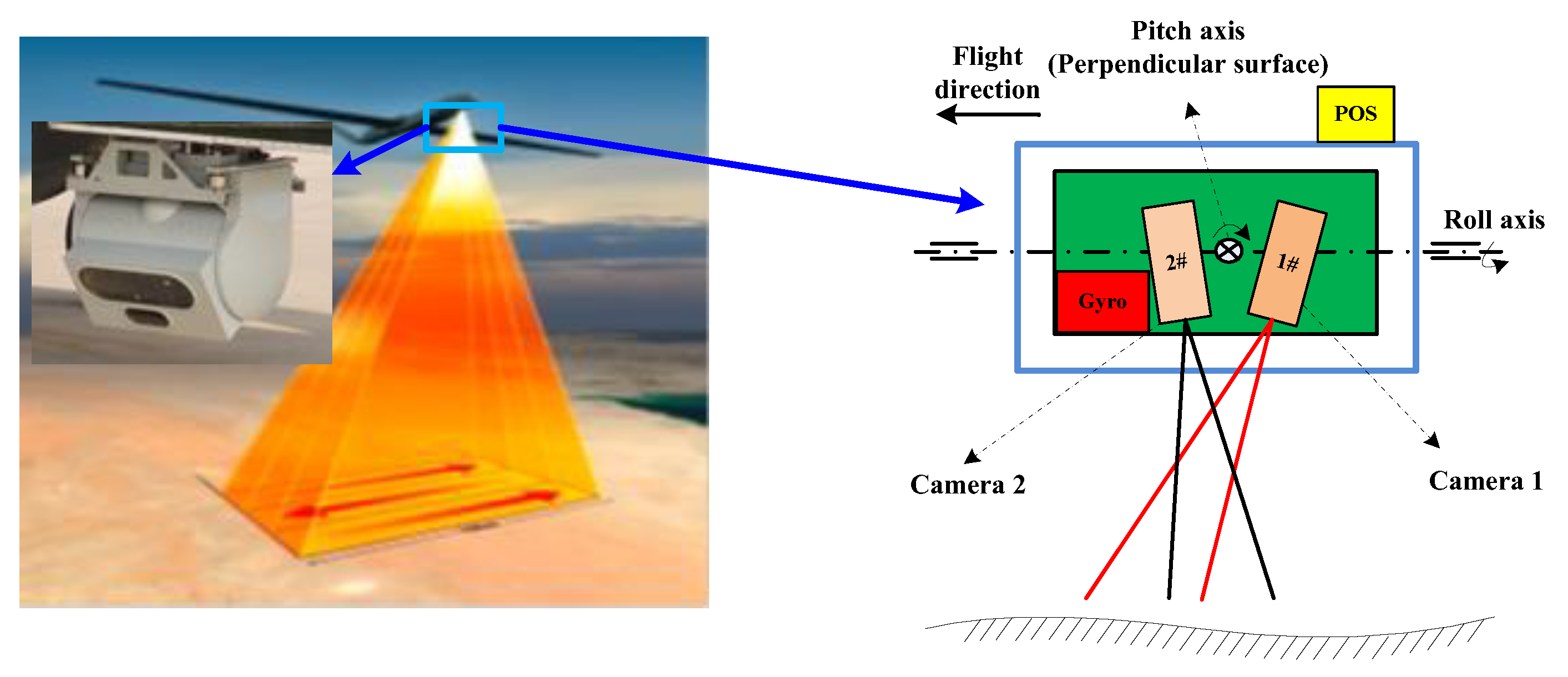
Figure 1. Structure of the multilevel 2D IMC system.
Photonics 10 01305 g001
Figure 2. The two-way wide-field scanning imaging system.
Photonics 10 01305 g002
Figure 3. The model of the optical path in the system.
Photonics 10 01305 g003
Figure 4. The relationship between the FSM coordinate system and the imaging auxiliary coordinate system.
Photonics 10 01305 g004
Figure 5. The relation between the gyro’s sensitive axis, the gyro coordinate system, and the imaging auxiliary coordinate system.
Photonics 10 01305 g005
Figure 6. A complete model of the 2D IMC system.
Photonics 10 01305 g006
Figure 7. A diagram of coarse 2D scanning commands.
Photonics 10 01305 g007
Figure 8. The relationship between the FSM angle and the secondary mirror plane.
Photonics 10 01305 g008
Figure 9. Calibration of optical coupling.
Photonics 10 01305 g009
Figure 10. The image motion coupling of FSM.
Photonics 10 01305 g010
Figure 11. The image motion coupling of the gyro.
Photonics 10 01305 g011
Figure 12. Tests on the 2D IMC. (a) Cross target image of original size; (b) Enlarged cross target image of 1D IMC; (c) Enlarged cross target image of 2D IMC without ODCR; (d) Enlarged cross target image of 2D IMC with ODCR.
Photonics 10 01305 g012
Figure 13. A clear strip chart.
Photonics 10 01305 g013
Figure 14. The results without IMC.
Photonics 10 01305 g014
Figure 15. The results with conventional IMC.
Photonics 10 01305 g015
Figure 16. The results with IMC with ODCR.
Photonics 10 01305 g016
Table 1. Calibration between FSM and the camera coordinate system.
ParameterCalibration ValueUnit
S x 0.003351032rad
S y −0.003855432rad
S z 0.006126106rad
ξ 0.005152212rad
k 0.51418/
f 451.2mm
Table 2. The calibrated results between the gyro and the camera coordinate system.
ParameterCalibration ValueUnit
G x 0.005097234rad
G y 0.003822271rad
G z −0.00757136rad
ϵ 0.005096361rad
Table 3. Calculation of image motion.
Compensation Precision.1D IMC2D IMC2D IMC with ODCR
Direction of Image Motion
M s t i l l in the roll direction0.2360.2360.236
M s t i l l in the pitch direction0.2270.2270.227
M in the roll direction (RMS)0.2260.210.235
M in the pitch direction (RMS)0.2040.1850.226
M m o t i o n in the roll direction (RMS)0.9560.890.997
M m o t i o n in the pitch direction (RMS)0.8990.8130.995
IMC error in the roll direction (RMS)1.652.620.46
IMC error in the pitch direction (RMS)2.513.470.57
The data in Table 3 are retained to three decimal places at most.
Disclaimer/Publisher’s Note: The statements, opinions and data contained in all publications are solely those of the individual author(s) and contributor(s) and not of MDPI and/or the editor(s). MDPI and/or the editor(s) disclaim responsibility for any injury to people or property resulting from any ideas, methods, instructions or products referred to in the content.