Abstract
In this paper, we propose a measurement method of micro-optical elements with parallel phase-shifting digital holographic phase imaging. This method can record four phase-shifting holograms with a phase difference of π/2 in a single shot and correct the pixel mismatch error of the polarization camera using a bilinear interpolation algorithm, thereby producing high-resolution four-step phase-shifting holograms. This method reconstructs the real phase information of the object to be measured through a four-step phase-shifting algorithm. The reproduced image eliminates the interference of zero-order images and conjugate images, overcoming the problem that traditional phase-shifting digital holography cannot be measured in real time. A simulation analysis showed that the relative error of this measurement method could reach 0.0051%. The accurate surface topography information of the object was reconstructed from an experimental measurement through a microlens array. Multiple measurements yielded a mean absolute error and a mean relative error for the vertical height of the microlens array down to 5.9500 nm and 0.0461%, respectively.
1. Introduction
With the rapid development of science and technology, micro-nano-devices such as microelectromechanical systems (MEMSs) [1] and microlens arrays have been widely used. They play a significant role in the precise measurement of the three-dimensional shapes of micro-nano-structures [2]. Based on traditional holography, digital holography technology [3] uses photoelectric sensing devices (such as charge-coupled diode (CCD) and complementary metal-oxide semiconductor (CMOS) devices) to replace traditional silver-halide dry plates, record digital holograms of a sample being tested, and store them in a computer. Then, a computer is used to simulate the diffraction wave to reconstruct the amplitude and phase images of the sample. This technology has the advantages of being fast, contactless, and free from fluorescent markers. Thus, this technology is widely used in applications such as surface topography measurements, particle field measurements [4], micro-nano-device detection [5], and combining metasurface technology [6,7] for phase modulation.
However, due to the interference of zero-order images and conjugate images, it is impossible to obtain a clear digital holographic reconstruction image. Studies have shown that phase-shifting digital holography technology, which combines phase-shifting technology [8,9] and digital holography technology, is an effective method to eliminate the interference of zero-order images and conjugate images. It offers a fast, non-destructive, and high-precision method for detecting the three-dimensional morphology and refractive index distribution of microscopic objects. At present, phase-shifting digital holography adopts digital in-line holography experimental devices with added phase-shifters. Traditional phase-shifting digital holography requires multiple holograms with different phase shifts to be recorded to eliminate zero-order images and conjugate images and reproduce aliasing-free phase/amplitude images. However, this technique faces problems such as a low phase reconstruction accuracy, low speeds, and being incapable of real-time measurement.
Many studies have attempted to solve the problem of zero-order image and conjugate image interference in digital holography technology and the problem that traditional phase-shifting digital holography technology cannot measure an object in real time. The studies can be primarily categorized into three types: the multi-CCD recording method, the pixel mask method, and the parallel beam-splitting method.
1.1. Parallel Phase-Shifting Technique Based on Multi-CCD Recording
The multi-CCD recording method is based on the separation and independence of multiple beam paths after spectroscopy. This technique utilizes multiple CCDs to simultaneously expose and individually record phase-shift interferograms with different phase shifts. In 2003, Sivakumar [10] built a parallel phase-shift interferometry device with four CCDs that could record four interferometric patterns with different phases at the same time. However, their system had a complex structure, required a large amount of space, and required a complex control system to control four CCDs at the same time to achieve parallel exposure, rendering it unsuitable for wide adoption. In 2014, Safrani and Abdulhalim [11] implemented an ultra-high-speed, real-time, high-resolution phase-shifting interferometry system based on the polarization-based Linnik interferometer. The system used three parallel CCD detectors to record interference patterns, with each CCD equipped with a precise achromatic phase mask, which could simultaneously acquire the interference pattern with a phase shift of π/2.
1.2. Parallel Phase-Shifting Technique Based on Pixel Masks
The pixel mask separation method is a technique that entails placing a custom-made mask over the CCD’s recording target surface. This mask ensures that each pixel on the CCD records a different phase shift. Afterward, the entire recorded interferogram is resampled and combined to generate multiple interferograms with distinct phase shifts. The concept behind the design of the division-of-focal-plane polarization camera employed in this study is derived from this principle. In 2004, Awatsuji et al. [12] simultaneously recorded multiple phase-shifting interferograms with one CCD by placing a special mask in front of the CCD recording target. In the same year, Millerd et al. [13] proposed to replace the phase mask with a pixel-level micro-polarization phase-shift array. The micro-polarization phase-shift array corresponded one-to-one to the pixels of the image plane. Based on this, a parallel phase shift was achieved, and the Twyman–Green dynamic interferometer was constructed. In 2005, Novak et al. [14] built a Fizeau dynamic interferometer. In 2006, Yoneyama [15] used another micro-phase delay array to achieve the phase delay corresponding to a single pixel. They also used four units as a group to change the direction of the corresponding main axis sequentially, thereby introducing the phase difference of π/2. They finally achieved the recording of four holograms in a single shot. In 2017, Tahara et al. [16] proposed a parallel phase-shifting digital holography technology using light-emitting diode (LED) incoherent light illumination based on light-wave space division multiplexing and polarization masks, and they captured incoherent holograms by using a single optical path parallel phase-shift device. In 2020, Liang et al. [17] proposed a Fresnel incoherent digital holographic imaging system [18] for recording multiple holograms and three-dimensional imaging in a single shot based on a geometric phase lens and a polarization imaging camera.
1.3. Parallel Phase-Shifting Technique Based on Parallel Beam Splitting
The parallel phase-shifting technique, based on the parallel beam-splitting method, utilizes beam-splitting elements like beam-splitting prisms, gratings, and so on, to divide the incident light beam into multiple segments. By employing the principles of polarization phase shifting or diffraction phase shifting, this technique enables the acquisition of multiple phase-shifted interferograms at various locations on the target surface of the CCD recording. Each segment of the beam undergoes a different phase shift, allowing for the generation of multiple interferograms with distinct phase shifts. In 2008, Kiire et al. [19] proposed a new type of single-exposure dual-wavelength orthogonal phase-shifting interferometer using polarizing prisms, diffraction gratings, and dual-wavelength lasers. It can acquire four phase-shifting interferograms simultaneously and measure moving objects. In 2009, Meneses-Fabian et al. [20] used the diffraction characteristics of a phase grating to record multiple phase-shifting interference patterns with a single shot and reconstructed the phase through a corresponding phase-shifting algorithm. In 2010, Chen et al. [21] built a parallel phase-shifting digital holographic imaging system using a glass plate and a beam-splitting module consisting of two polarizing beam splitters and a prism. By measuring the surface topographies of a plane mirror and a Mitutoyo precision gauge block, they verified the measurement accuracy and repeatability of their system. In 2011, Gao et al. [22,23] built an in-line recording parallel phase-shifting interference microscope based on a beam-splitting prism parallel phase-shifting module; achieved the separation of the object and reference light beams from a single beam-splitting prism, as well as the common path of the object and reference light beams from a double beam-splitting prism; and obtained two parallel phase-shifting interference patterns with a signal exposure. In 2016, Yang et al. [24] placed a two-dimensional diffraction grating on the Fourier plane of the detection optical path of a standard in-line holographic phase microscope and compared these with different overall phase-shifts for different diffraction orders. Images of the same sample were spatially separated so that four phase-shifting interferograms could be recorded simultaneously in the camera plane.
Parallel phase-shifting digital holography can obtain multiple interference patterns with different phase shifts simultaneously through a single shot, which can eliminate the interference of zero-order images and conjugate images and perform the real-time measurement of an object. Compared to off-axis digital holography, parallel phase-shifting digital holography possesses several advantages, including higher accuracy in phase measurement, improved spatial resolution, and a reduced noise level. Based on this, in this paper, we propose a measurement method of parallel phase-shifting digital holographic phase imaging.
A parallel phase-shifting digital holographic imaging system, utilizing a division-of-focal-plane polarization camera, has been designed and implemented to tackle the precise phase measurement challenge of micro-optical elements in digital holography and accurately determine their surface topography. Compared to alternative methods achieving parallel phase shifting, the designed system significantly simplifies the complexity associated with the optical path design for parallel phase-shifting digital holographic recording. The reproduced image eliminates the interference of zero-order images and conjugate images. The experimental device has the advantages of having a compact structure, being highly parallel, and having high stability.
2. Basic Principle
The parallel phase-shifting digital holographic phase imaging measurement method proposed in this paper is implemented using a polarization camera. The division-of-focal-plane polarization camera is an imaging sensor composed of polarization-sensitive pixels. Each polarization-sensitive pixel is composed of a micro-polarizer and a photodetector [25,26,27], and corresponds one-to-one to a CMOS pixel on a spatial scale, so the field of view of the CMOS can be fully utilized. The micro-polarizer array is integrated and placed on the focal plane of the photodetector surface. In addition, the transmission directions of the four adjacent polarization units of the micro-polarizer array are different by 45°. Each polarization unit consists of micro-polarizers with polarization directions of 0°, 45°, 90°, and 135°.
Based on the Mach–Zehnder interference optical path, the schematic diagram of the parallel phase-shifting digital holography experiment based on the division-of-focal-plane polarization camera is shown in Figure 1. The laser beam generated by the fiber-coupled He-Ne laser passes through a collimation system, then it passes through the linear polarizer to become linearly polarized light and is divided into P-polarized light and S-polarized light by polarization beam-splitter prism 1 (PBS1). The P-polarized light is the object beam, and the S-polarized light is the reference beam. The P-polarized light is diverted by plane reflector 1, and the light is vertically incident on the measured object through microscopic objective lens 1 to polarization beam-splitter prism 2 (PBS2). The S-polarized light is diverted by plane reflector 2 and then passes through microscopic objective lens 2 to polarization beam-splitter prism 2. The two beams are combined by polarization beam-splitter 2 (PBS2) and pass through the 1/4-wave plate (QWP). The two linearly polarized lights become left-handed circularly polarized light and right-handed circularly polarized light through the 1/4-wave plate. They then enter the polarization camera through the imaging lens. The phase shift is generated by the micro-polarizer array of the polarization camera. The digital hologram is recorded via the target surface of the polarization camera.
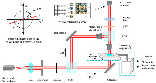
Figure 1.
Schematic diagram of the optical path of the parallel phase−shifting digital holography experiment.
The object and reference beams split by the polarization beam-splitter prism are expressed with the Jones matrix as follows:
where and represent the amplitude distribution of the object beam and the reference beam, respectively, and and represent the phase distribution of the object beam and the reference beam, respectively. Two mutually orthogonal beams, the object beam and the reference beam, pass through a 1/4-wave plate with the main axis direction of the wave plate being 45° from the polarization direction of the object beam and the reference beam. The two linearly polarized beams become mutually orthogonal circularly polarized lights, which can be expressed as follows:
where is the Jones matrix corresponding to when the axis direction of the 1/4-wave plate is 45° to the polarization direction of the object beam and the reference beam, and
Having passed through a linear P-polarizer, whose polarization direction is at an angle () to the object beam (horizontal direction), if the mutually orthogonal circularly polarized object and reference beams become linearly polarized beams with the same polarization direction, the object and reference beams can be, respectively, expressed as:
where is the Jones matrix corresponding to the angle () between the vibration transmission direction of the linear P-polarizer and the object beam (horizontal direction), and . After the object beam and the reference beam pass through the linear polarizer, the polarization directions of the two light waves become the same. At this time, interference occurs on the CCD target surface, and the intensity distribution of the interferogram recorded with the CCD target surface is expressed as
where is the phase difference between the object beam and the reference beam. It can be seen that by changing the value of , that is, by rotating the angle of the polarizer, an interferogram with different phase shifts can be obtained.
In this study, we used a polarization camera to record digital holograms. According to Equation (5), the intensity of the holograms is related to twice the angle () between the object beam wave (horizontal direction) and the polarization direction of each polarization unit. Each polarization unit in the polarization camera micro-polarizer array is composed of micro-polarizers with polarization directions of 0°, 45°, 90°, and 135°; then, the intensity distributions of the four digital holograms recorded on the target surface of the polarization camera are
Because the digital hologram recorded with the polarization camera loses spatial resolution, the resolution is only 1/4 of the resolution of the original polarization image taken with the polarization camera. To correct the pixel mismatch error, it is necessary to interpolate the four phase-shifting holograms [28]. After interpolation, the resolution of the four phase-shifting holograms with high resolution is the same as that of the original polarization image. The high-resolution four phase-shifting holograms are processed through a four-step phase-shifting algorithm to obtain the wrapped-phase information of the object, and then the phase-unwrapping process is performed to obtain the real three-dimensional shape information of the object. The relative phase distribution obtained via the four-step phase-shifting algorithm is
3. Simulation
In this study, we used MATLAB to program the interference of the object beam and the reference beam. The phase-shift amount was added to the reference beam to obtain four phase-shift holograms to implement the digital holography recording process. The four phase-shifting holograms obtained with the interference of the object beam and the reference beam only corresponded to a single phase shift. Therefore, it was necessary to extract the corresponding pixel points of the four phase-shifting holograms based on the arrangement of the micro-polarizer array and then fuse them into the real original polarization image recorded with the polarization camera. The polarization image was down-sampled to obtain four low-resolution sub-images with different polarization directions. However, the obtained sub-images lost their spatial resolution. To correct the pixel mismatch error, interpolation between them was performed again. Finally, a phase-shifting hologram with the same resolution as that of the polarized original image was obtained. The processing flow is shown in Figure 2, where an original polarized image with a resolution of 8 × 8 pixels is shown as an example.
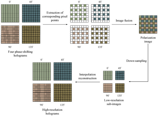
Figure 2.
Process flow of polarization phase−shift simulation.
In this paper, the simulated phase object in the form of a microlens array is taken as an example. The simulated height was 5 µm, as shown in Figure 3a. As shown in Figure 3b, four phase-shift holograms were obtained by adding the phase shift to the reference beam, which then interfered with the object beam that contained object information. The original polarized image was obtained via hologram fusion processing after the corresponding pixel points were extracted, as shown in Figure 3c. Then, four low-resolution holograms with different polarization directions were separated from the original polarization image, and the four-step phase-shifting hologram obtained at this time lost its spatial resolution, as shown in Figure 3d. The low-resolution hologram was processed via bilinear interpolation to obtain a high-resolution four-step phase-shifting hologram, as shown in Figure 3e. The four-step phase-shifting algorithm and the phase-unwrapping algorithm to obtain the real phase information were applied, and the reconstructed two-dimensional phase map and three-dimensional phase map are shown in Figure 3f. By comparing the reconstruction result with the simulated original phase, the residual distribution of the phase reconstruction was obtained, as shown in Figure 3g. The peak-to-valley (PV) and root mean square (RMS) values of the residual were 0.0470 µm and 0.0101 µm, respectively.
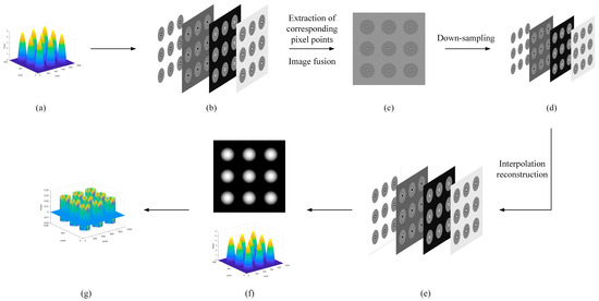
Figure 3.
Phase object simulation processing flow for microlens array shapes. (a) Original phase; (b) four phase−shifting holograms; (c) polarization image; (d) low−resolution holograms; (e) high−resolution holograms; (f) reconstruction phase; (g) residuals.
To display the simulation phase reconstruction results more intuitively, a section line was selected for a single phase object with the shape of a microlens, as shown in Figure 4. The vertical height of the actual measured single phase object was 4.9995 µm. Compared with the originally generated height of 5 µm, the relative error of the simulation result was 0.0051%.
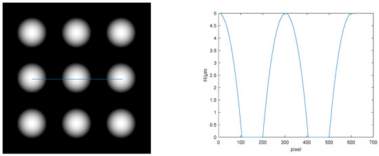
Figure 4.
Selection of phase object cross-sections of the shape of a single microlens.
Through the program simulation, the accurate three-dimensional geometry information of the object was obtained, verifying the polarization phase-shift simulation process proposed in this paper. According to the simulation processing results, the relative error of the algorithm-reconstructed microlens-shaped phase object height was only 5/100,000 of the simulated original height.
4. Experiment and Result Analysis
In the experiment, a fiber-coupled He-Ne laser with a wavelength of 632.8 nm and a 10× microscope object lens were used. A Mako G-508B POL polarization camera was equipped with a Sony IMX250MZR CMOS sensor, which used the latest four-directional polarization technology. The on-chip nanowire polarizer supported four directions (0°, 45°, 90°, and 135°). Four pixels worked together to make up a calculation unit to determine the angle of intensity and polarization for each pixel. The resolution of the polarization camera was 2464 (H) × 2056 (V). The size of a single pixel was 3.45 µm × 3.45 µm. The maximum full frame rate of the camera was 23 fps. A parallel phase-shifting digital holographic experimental device, as shown in Figure 5, was built following the schematic diagram of the experimental optical path in Figure 1.
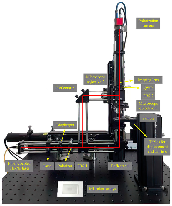
Figure 5.
Picture of the parallel phase−shifting digital holography experimental apparatus.
We first built the experimental device based on the experimental optical path and the parameters of the components. The optical path was adjusted to be in-line without adding the object under test. Next, we calibrated the 1/4-wave plate so that the direction of the main axis of the 1/4-wave plate was 45° to the polarization directions of the object and reference beams, which were orthogonal to each other, and then we added the calibrated 1/4-wave plate into the optical path. The role of the imaging lens was to image the object in equal proportions. We placed a microlens array, adjusted the angle of the polarizer to change the intensity ratio of the object beam (P-polarized light) and reference beam (S-polarized light), adjusted the distance between the microlens array and the microscope object lens, and searched for the focus position until a clear digital holographic image was displayed on the computer.
The micro-optical element measured in this study was a microlens array made of cyclo-olefin polymers (COPs). The microstructure has a bottom surface shaped like a regular hexagon, and the arrays are arranged in a regular hexagonal pattern, as shown in Figure 5. The original polarization image obtained in the experiment and the four high-resolution holograms obtained after the bilinear interpolation processing of the four-step phase-shifting hologram with a loss of spatial resolution are shown in Figure 6.

Figure 6.
Original polarization image and four−step phase−shifting holograms.
Using the four-step phase-shifting algorithm, the four phase-shifting holograms after correcting the pixel mismatch error were processed. The wrapped phase of the microlens array was obtained, as shown in Figure 7a. The unwrapped phase could be obtained by using the least squares unwrapping method based on a discrete cosine transform, as shown in Figure 7b. The real phase diagram of the microlens array obtained after phase distortion was eliminated is shown in Figure 7c,d.

Figure 7.
Phase processing results of microlens array. (a) Wrapping phase; (b) unwrapping phase; (c) 2−D phase; (d) 3−D phase.
To display the phase reconstruction result of the microlens array more intuitively, a section line was selected for a single microlens, as shown in Figure 8. The microlens array was measured with a ZYGO white light interferometer. The measured vertical height was 12.9170 µm. The lateral dimension of a single microlens was 317.6870 µm.
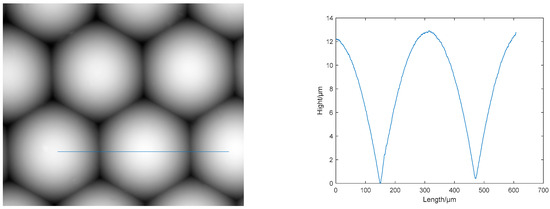
Figure 8.
Selection of section lines of a single microlens.
To remove the effects of random factors on the measurement results, the object was measured and the section line was selected multiple times. The measurement results are shown in Table 1. The mean height of the measured microlens array was 12.9230 µm. The lateral dimension of a single microlens was 322 µm. By comparing the measurement results of this method with the measurement results of the white light interferometer, it was determined that the mean absolute error of the height was 5.9500 nm, the mean relative error was 0.0461%, the absolute error of the lateral dimension of a single microlens was 4.3130 µm, and the relative error was 1.3576%. These results showed that the measurement method was highly accurate. The relative error of the experimental measurement results was nine times the relative error of the simulation results. The analysis indicated that the error was a systematic error in the experimental measurement process, such as the effect of the calibration accuracy of the 1/4-wave plate and the effect of noise introduced by the measurement environment.

Table 1.
Experimental measurement results of a microlens array.
5. Conclusions
In this paper, we propose a measurement method of parallel phase-shifting digital holographic phase imaging. A parallel phase-shifting digital holographic imaging system, utilizing a division-of-focal-plane polarization camera, has been designed and implemented to tackle the precise phase measurement challenge of micro-optical elements in digital holography and accurately determine their surface topography. The parallel phase-shifting digital holography experimental device constructed in this study could acquire four-step phase-shifting holograms in a single shot. The experimental device has the advantages of having a compact structure, being highly parallel, and having high stability. A high-resolution four-step phase-shifting hologram was obtained by performing experimental measurements on a microlens array as the phase object and correcting pixel mismatch errors using a bilinear interpolation algorithm. Then, the real phase information of the object was obtained via reconstruction using a four-step phase-shifting algorithm. The reconstructed image eliminated the interference of zero-order images and conjugate images. The mean relative error of the height of the microlens array measured in the experiment reached 0.0461%, indicating the high accuracy of this measurement method and its applicability to the field of the surface topography measurement of micro-optical elements.
Author Contributions
B.L.: conceptualization, methodology, data curation, formal analysis, writing—original draft; X.F.: methodology, validation, writing; A.T.: investigation, supervision, writing—review and editing; S.W.: methodology, data curation; R.Z.: data curation; H.W.: conceptualization, methodology; X.Z.: supervision. All authors have read and agreed to the published version of the manuscript.
Funding
This research was funded by the Basic Research (grant number JCKY2020426B009) and Shaanxi Provincial Science and Technology Department (grant numbers 2022JM-345, 2023-YBGY-006).
Institutional Review Board Statement
Not applicable.
Informed Consent Statement
Not applicable.
Data Availability Statement
Data underlying the results presented in this paper are not publicly available at this time but may be obtained from the authors upon reasonable request.
Acknowledgments
We thank the other members of the digital holography group at the Xi’an Technological University for their discussions and feedback on this work.
Conflicts of Interest
The authors declare no conflict of interest.
References
- Asundi, A.; Singh, V.R. Digital holography for MEMS application. In Proceedings of the Advances in Imaging, Vancouver, BC, Canada, 13–14 October 2018. [Google Scholar]
- Song, X.F.; Tang, Z.; Wang, H.Y. Application of digital holography in microscopic object measurement. In Proceedings of the 2009 Chinese Control and Decision Conference, Guilin, China, 17–19 June 2009; pp. 2057–2060. [Google Scholar]
- Min, J.W.; Yfao, B.L.; Ketelhut, S.; Engwer, C.; Greve, B.; Kemper, B. Simple and fast spectral domain algorithm for quantitative phase imaging of living cells with digital holographic microscopy. Opt. Lett. 2017, 42, 227–230. [Google Scholar] [CrossRef] [PubMed]
- Zeng, Y.N.; Lu, J.S.; Hu, X.D.; Chang, X.Y.; Liu, Y.; Zhang, X.; Wang, Y.Y.; Sun, Q. Axial displacement measurement with high resolution of particle movement based on compound digital holographic microscopy. Opt. Commun. 2020, 475, 126300. [Google Scholar] [CrossRef]
- Liu, B.C.; Feng, D.Q.; Feng, F.; Tian, A.L.; Liu, W.G. Maximum a posteriori-based digital holographic microscopy for high-resolution phase reconstruction of a micro-lens array. Opt. Commun. 2020, 477, 126364. [Google Scholar] [CrossRef]
- Zheng, G.; Mühlenbernd, H.; Kenney, M.; Li, G.; Zentgraf, T.; Zhang, S. Metasurface holograms reaching 80% efficiency. Nat. Nanotechnol. 2015, 10, 308–312. [Google Scholar] [CrossRef] [PubMed]
- Zhou, Y.; Kravchenko, I.I.; Wang, H.; Zheng, H.; Gu, G.; Valentine, J. Multifunctional metaoptics based on bilayer metasurfaces. Light Sci. Appl. 2019, 8, 80. [Google Scholar] [CrossRef]
- Xia, P.; Ri, S.E.; Inoue, T.; Awatsuji, Y.; Matoba, O. Dynamic phase measurement of a transparent object by parallel phase-shifting digital holography with dual polarization imaging cameras. Opt. Lasers Eng. 2021, 141, 106583. [Google Scholar] [CrossRef]
- Xia, P.; Wang, Q.H.; Ri, S.E. Random phase-shifting digital holography based on a self-calibrated system. Opt. Express 2020, 28, 19988–19996. [Google Scholar] [CrossRef]
- Sivakumar, N.R. Large surface profile measurement with instantaneous phase-shifting interferometry. Opt. Eng. 2003, 42, 367–372. [Google Scholar] [CrossRef]
- Safrani, A.; Abdulhalim, I. Real-time phase shift interference microscopy. Opt. Lett. 2014, 39, 5220–5223. [Google Scholar] [CrossRef]
- Awatsuji, Y.; Sasada, M.; Kubota, T. Parallel quasi-phase-shifting digital holography. Appl. Phys. Lett. 2004, 85, 1069–1071. [Google Scholar] [CrossRef]
- Millerd, J.E.; Brock, N.J.; Hayes, J.B.; North-Morris, M.B.; Novak, M.; Wyant, J.C. Pixelated phase-mask dynamic interferometer. In Proceedings of the SPIE 49th Annual Meeting, Denver, CO, USA, 2 August 2004; pp. 304–314. [Google Scholar]
- Novak, M.; Millerd, J.; Brock, N.; North-Morris, M.; Hayes, J.; Wyant, J. Analysis of a micropolarizer array-based simultaneous phase-shifting interferometer. Appl. Opt. 2005, 44, 6861–6868. [Google Scholar] [CrossRef] [PubMed]
- Yoneyama, S. Simultaneous observation of phase-stepped photoelastic fringes using a pixelated microretarder array. Opt. Eng. 2006, 45, 083604. [Google Scholar] [CrossRef]
- Tahara, T.; Kanno, T.; Arai, Y.; Ozawa, T. Single-shot phase-shifting incoherent digital holography. J. Opt. 2017, 19, 065705. [Google Scholar] [CrossRef]
- Liang, D.; Zhang, Q.; Wang, J.; Liu, J. Single-shot Fresnel incoherent digital holography based on geometric phase lens. J. Mod. Opt. 2020, 67, 92–98. [Google Scholar] [CrossRef]
- Choi, K.; Joo, K.-I.; Lee, T.-H.; Kim, H.-R.; Yim, J.; Do, H.; Min, S.-W. Compact self-interference incoherent digital holographic camera system with real-time operation. Opt. Express 2019, 27, 4818–4833. [Google Scholar] [CrossRef]
- Kiire, T.; Nakadate, S.; Shibuya, M. Simultaneous formation of four fringes by using a polarization quadrature phase-shifting interferometer with wave plates and a diffraction grating. Appl. Opt. 2008, 47, 4787–4792. [Google Scholar] [CrossRef]
- Meneses-Fabian, C.; Rodriguez-Zurita, G.; Encarnacion-Gutierrez, M.-d.-C.; Toto-Arellano, N.I. Phase-shifting interferometry with four interferograms using linear polarization modulation and a Ronchi grating displaced by only a small unknown amount. Opt. Commun. 2009, 282, 3063–3068. [Google Scholar] [CrossRef]
- Chen, L.C.; Yeh, S.L.; Tapilouw, A.M.; Chang, J.C. 3-D surface profilometry using simultaneous phase-shifting interferometry. Opt. Commun. 2010, 283, 3376–3382. [Google Scholar] [CrossRef]
- Gao, P.; Yao, B.L.; Min, J.W.; Guo, R.L.; Zheng, J.J.; Ye, T. Parallel two-step phase-shifting microscopic interferometry based on a cube beamsplitter. Opt. Commun. 2011, 284, 4136–4140. [Google Scholar] [CrossRef]
- Gao, P.; Yao, B.L.; Min, J.W.; Guo, R.L.; Zheng, J.J.; Ye, T.; Harder, I.; Nercissian, V.; Mantel, K. Parallel two-step phase-shifting point-diffraction interferometry for microscopy based on a pair of cube beamsplitters. Opt. Express 2011, 19, 1930–1935. [Google Scholar] [CrossRef]
- Yang, T.D.; Kim, H.J.; Lee, K.J.; Kim, B.M.; Choi, Y.W. Single-shot and phase-shifting digital holographic microscopy using a 2-D grating. Opt. Express 2016, 24, 9480–9488. [Google Scholar] [CrossRef] [PubMed]
- Li, Z.; Hong, E.; Zhang, X.; Deng, M.; Fang, X. Perovskite-Type 2D Materials for High-Performance Photodetectors. J. Phys. Chem. Lett. 2022, 13, 1215–1225. [Google Scholar] [CrossRef] [PubMed]
- Deng, M.; Li, Z.; Deng, X.; Hu, Y.; Fang, X. Wafer-scale heterogeneous integration of self-powered lead-free metal halide UV photodetectors with ultrahigh stability and homogeneity. J. Mater. Sci. Technol. 2023, 164, 150–159. [Google Scholar] [CrossRef]
- Hu, Y.; Li, Z.; Fang, X. Solution-prepared AgBi2I7 Thin Films and Their Photodetecting Properties. J. Inorg. Mater. 2023, 38, 1055–1061. [Google Scholar] [CrossRef]
- Wang, S.Q.; Liu, B.C.; Wang, H.J.; Zhu, Y.H.; Wang, K.; Ren, K.X.; Zhang, Y.W.; Tian, A.L. Improving the phase reconstruction accuracy of simultaneous phase-shifted lateral shearing interferometry using a polarization redundant sub-region interpolation method. Opt. Express 2022, 30, 34297–34313. [Google Scholar] [CrossRef] [PubMed]
Disclaimer/Publisher’s Note: The statements, opinions and data contained in all publications are solely those of the individual author(s) and contributor(s) and not of MDPI and/or the editor(s). MDPI and/or the editor(s) disclaim responsibility for any injury to people or property resulting from any ideas, methods, instructions or products referred to in the content. |
© 2023 by the authors. Licensee MDPI, Basel, Switzerland. This article is an open access article distributed under the terms and conditions of the Creative Commons Attribution (CC BY) license (https://creativecommons.org/licenses/by/4.0/).