Article

Removal Mechanisms and Microstructure Characteristics of Laser Paint Stripping on Aircraft Skin Surface

1
School of Materials Science and Engineering, Harbin Institute of Technology, Shenzhen, Shenzhen 518055, China
2
State Key Laboratory of Advanced Welding and Joining, Harbin Institute of Technology, Harbin 150001, China
*
Authors to whom correspondence should be addressed.
Photonics 2023, 10(1), 96; https://doi.org/10.3390/photonics10010096
Submission received: 14 December 2022 / Revised: 9 January 2023 / Accepted: 12 January 2023 / Published: 16 January 2023
(This article belongs to the Special Issue Ultrafast Laser Irradiation in Surface Engineering and Tribology)

Abstract

:
As a non-contact and non-destructive technology, laser cleaning provides an alternative method for the paint stripping of aircraft skins. Herein, the particular multi-layer paint on the aluminum alloy aircraft skin surface was stripped by adjusting laser parameters. Beyond expectation, multi-layer paint led to a highly complex surface as opposed to the ordinary single-layer paint after laser cleaning. The surface morphology, chemical compositions, and surface functional groups of the samples were analyzed, and the successful depaint parameters were found in this experiment with damage free of the aluminum substrate, i.e., laser energy density of 5.09 J/cm2 and scanning speed of 700 mm/s. More importantly, this paper revealed that the mechanisms of laser paint stripping from Al alloy aircraft skin are thermal decomposition, evaporation, and spallation. After laser cleaning, the surface nanoindentation hardness with paint completely stripped and undamaged was increased by 3.587% relative to that of the conventional mechanical lapping sample. The improvement of nanoindentation hardness was also confirmed by the microstructure characterized with electron backscatter diffraction (EBSD) in which plastic deformation led to strain hardening of the substrate surface. This study lays a solid foundation for large-scale, high-efficiency, and low-pollution removal of more complex paint layers on aircraft surfaces in the future.

1. Introduction

The function of aircraft skin is to maintain the shape of the aircraft, increase the reflection of sun light, and make it have good aerodynamic characteristics [1,2]. The aircraft skin is directly exposed to a high-pressure and low-temperature environment, which makes the shin of an aircraft extremely important. During the service of an aircraft, mechanical scratches, electromagnetic radiation, and complex service environments with temperature and humidity differences may cause paint cracking, aging, peeling, and damage to parts of fuselage, requiring regular maintenance of the aircraft [3,4,5,6]. In the process of aircraft overhaul, the paints need to be completely removed so the substrate can be checked for defects [7,8]. The paint-stripping method of aircraft skin mainly includes mechanical treatment and chemical methods at present, which are not only costly, low efficiency, and cause serious environmental pollution, but also likely cause certain damages to the substrate of the skin and other parts [9,10,11,12]. Moreover, these methods are likely to cause physical injury to the on-site operators. Therefore, an alternative efficient, non-contact, non-destructive, highly motived, and environmentally friendly cleaning technology is needed.
Laser cleaning utilizes the interaction mechanism of laser and materials to selectively remove the attachments on the substrate with damage free or controllable damage to the substrate [13,14,15,16,17]. During the cleaning process, the attachments on the surface to be treated absorb the laser energy, destroy the binding force between the removed object and the substrate, and make the attachments peel off through ablation, vibration, and other action processes. It has the outstanding advantages of non-contact, selective cleaning, good cleaning effect, potentially highly automated, and high precision [18,19,20,21,22]. In 1965, Schawlow [23] first proposed the “laser eraser”, which used laser pulses to remove ink on the paper without damaging the paper. Subsequently, in 1969, Bedair and Smith [24] used a Q-switched laser to remove contaminants on the silicon surface without damaging the substrate, and raised the concept of “laser cleaning”. With the advancement of lasers, laser-cleaning technology has developed rapidly in recent years, which has significant advantages in the preservation of cultural relics, paint striping, rusting cleaning, and oxide film removal in diverse industrial applications [25,26,27,28,29]. Palomar [30] evaluated the effect of laser cleaning for pure silver artifacts by laser with different wavelengths and considered that a laser with a wavelength of 532 nm was the most suitable. Yoo [31] studied the alteration of the microstructure and mechanical properties of SS304L after corrosion removal via the laser surface cleaning, and suggested a relatively low-energy-input process with multiple repetitions to minimize the alterations. Li [32] achieved liquid-assisted pulsed laser cleaning of TA15 titanium alloy oxide film and investigated the laser-cleaning effect, surface structure, and cleaning mechanism. Tian [33] innovatively carried out laser cleaning on the natural marine micro-biofoulings on the surface of aluminum alloy used in ships and proved the effectiveness of laser cleaning based on the analysis of surface morphology and surface properties, which provided the possibility of anti-fouling in subsequent use. Laser-cleaning technology can remove a wide range of types and scope, and has gradually developed into an alternative technology to other cleaning methods.
The laser-cleaning technology has gradually matured; the research on the laser paint stripping of aircraft skin has given increasing attention, and its market potential is vast. Tsunemi [34] used a high-power pulsed TEA CO2 laser to strip the paints on the surface of aircraft skin with Al alloy and fiber-reinforced composite materials, while the substrates were not damaged. Arthur [35] installed a continuous fiber laser on a mobile robot to selectively remove paint on small and medium-sized military aircraft, which can adjust the laser beam according to the shape of the fuselage to automatically and accurately control the paint removal trajectory. Wang [36] utilized a 30 W pulsed laser to remove the paint with a thickness of 31.5 μm on the aircraft skin surface, which mildly damaged the oxide film without damaging the metal substrate. Zhu [37] fully stripped paint with a thickness of 130 μm on the surface of aircraft Al alloy skin under the action of a medium-power pulsed laser, and verified that there was no reduction in friction and wear performance, micro-hardness, and corrosion resistance, but a certain plastic deformation was produced. Of particular note, it has important application value in the depainting of aircraft skin surface. However, the coating on the surface of aircraft skin is mostly thick multi-layer paint, and local warping may occur at the joints of different paint layers during the cleaning process, resulting in complex changes in surface roughness and cleaning mechanisms. Laser paint stripping is the result of a combination of mechanisms, and most of the current research conclusions are inferred from the observed phenomena [9,38,39,40]. What has been overlooked is that the dominant effect of laser removal differs when it acts on different areas of the material surface, and more research is needed to complete the mechanisms of laser paint stripping. Additionally, a large amount of relevant literature shows that the research of laser paint stripping on Al alloy surface is concerned with wrought Al alloy, and the research on casting Al alloy is rare. The microstructure of wrought Al alloy and casting Al alloy are significantly different, and the changes in the microstructure of casting Al alloys during laser cleaning still need to be studied. At present, laser-cleaning technology is still far from meeting the demand for efficient and high-quality maintenance, and the research on the influence of lasers on the substrate is still in the basic research stage, which is a serious challenge for the flight safety of aircrafts.
At present, the removal of paint on the surface of aircraft skin still relies on traditional stripping technology, which can pay more attention to the environment-friendly laser-cleaning technology. This paper demonstrated that laser cleaning effectively removes the multi-layer on the aircraft skin surface while avoiding damage to the casting Al alloy substrate or the damage is acceptable, and takes note of the change of the substrate surface property after laser cleaning. A nanosecond pulsed fiber laser was used to clean the coating on the skin surface of Boeing series aircraft, and samples at different laser fluence and scanning speed were obtained. The surface morphology, chemical compositions, and surface functional groups of the samples were analyzed to evaluate the cleaning quality and characterize the surface property. Then, the grain dislocation mechanism subjected to laser of the substrate was identified, which revealed the underlying nanoindentation hardness enhancement after laser cleaning. Furthermore, we studied the influence of laser-cleaning process on the surface roughness and stripping thickness to better select process parameters, and preliminarily revealed and discussed the laser paint stripping mechanisms from two aspects: the action of small laser energy on the paint and the action of large laser energy on the substrate, which can be helpful to the application of laser cleaning in aircraft skin paint removal.

2. Experimental Procedure
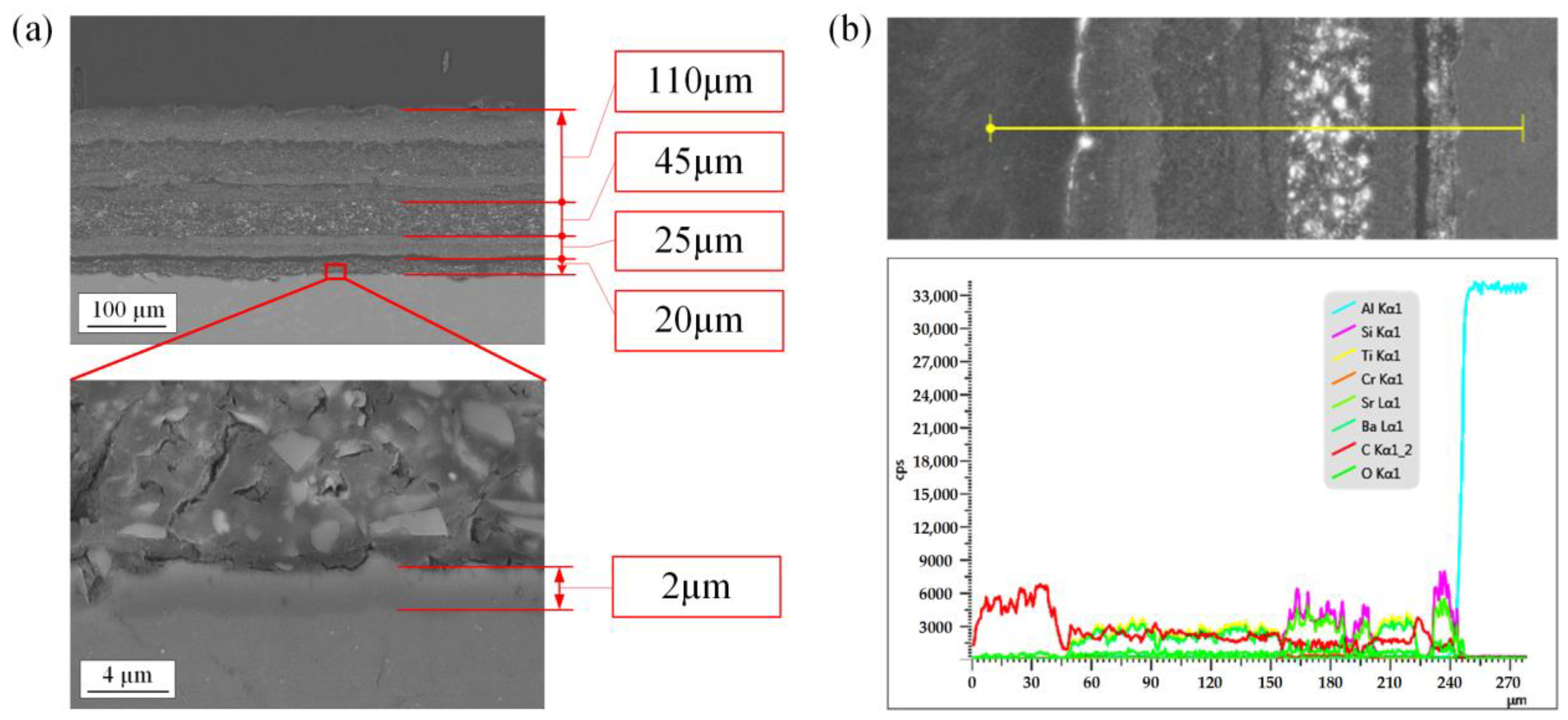
2.1. Materials

The experimental materials were Boeing 737 aircraft skins with coatings. As shown in Figure 1, a field emission scanning electron microscope (FE-SEM, ZEISS SUPRA® 55, ZEISS, Germany) with energy dispersive spectroscopy (EDS) attachment was used for cross-section observation and energy spectrum analysis of the original sample. As presented in Figure 1a, there are four layers of paint on the aluminum substrate, with a total thickness of about 200 μm, which are coated alternately by polyurethane paint and epoxy paint. The substrate is A357 Al alloy, and there is a uniform anodic oxide film about 2 μm thick between the paint and the aluminum substrate. It can be seen from the energy spectrum results in Figure 1b that all elements content of different paint is obviously differentiated, according to which the paint can be clearly layered.

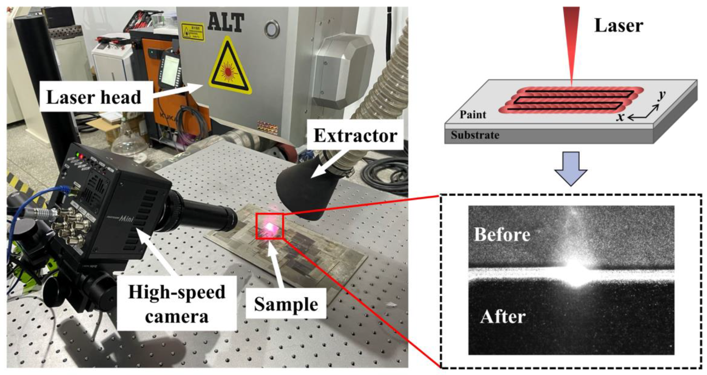
2.2. Laser-Cleaning Experiment

The nanosecond fiber laser (YLPN-100-30x100-1000, IPG, Oxford, MA, USA) was used to remove the paint on the skin surface in an ambient atmosphere; the cleaning system and laser scanning strategy are shown in Figure 2. The laser beam was output from the optical resonator and transmitted to the laser head through an optical fiber. The laser beam was collimated with a f75mm collimated lens, and transmitted to a two-axis scanning galvo scanner system. The laser was then focused to the sample surface with a flat field lens. Since the laser is a multi-mode laser, the focused laser beam distribution is a near flat top. The focused spot size is 1 mm in diameter to provide the best energy density. The cleaning process was observed by a high-speed camera (Fastcam Mini UX100, Photron, Tokyo, Japan). The main parameters of the laser are presented in Table 1. Since the coating on the aircraft skin surface is the multi-layer paint, different laser fluences and scanning speeds lead to more complex surface topography compared with the single-layer paint, which affects the surface roughness Ra and stripping thickness H. Thus, a general full factorial experiment with two factors, i.e., laser fluence F and scanning speed v, each containing six levels, was designed to observe the cleaning effect within a large process window and to analyze the trends of roughness and stripping thickness under different cleaning effects. The experimental factors and their levels are listed in Table 2. We set the laser power to be 200–700 W, the repetition rate to be 10 kHz, so the max pulsed energy can reach up to 70 mJ/pulse, the laser pulse duration to 100 ns, the line spacing (hatch) of the laser scanning path to 0.2 mm, and the scanning time to once. The laser fluence was calculated as follows:
F = P / f · S
where F is the laser fluence, P is the laser power, f is the repetition rate, and S is the laser spot area.

2.3. Surface Characterization

The macro morphology and micromorphology of the sample surfaces were analyzed by optical microscope (OM, GX71, OLYMPUS, Tokyo, Japan) and FE-SEM, respectively. The Fourier transform infrared spectroscopy of the samples were collected using the ATR mode of Fourier transform microscopic infrared spectrometer (FTIR, Thermo Nicolet iS50 Continuum, Thermo Fisher, Waltham, MA, USA). The microhardness was obtained by a nanomechanical tester (iMicro, KLA, Milpitas, CA, USA). Five points were measured for each sample and the average value was taken. A digital microscope (VH-ZST, KEYENCE, Osaka, Japan) was used to measure the surface roughness and stripping thickness of the uncleaned surface and the laser-cleaned surface, which were measured three times and then averaged, where the Ra of the uncleaned surface was 3.595 µm. Electron backscatter diffraction (EBSD, ZEISS SUPRA® 55, ZEISS, Oberkochen, Germany) was used to observe the grain structure.

3. Results

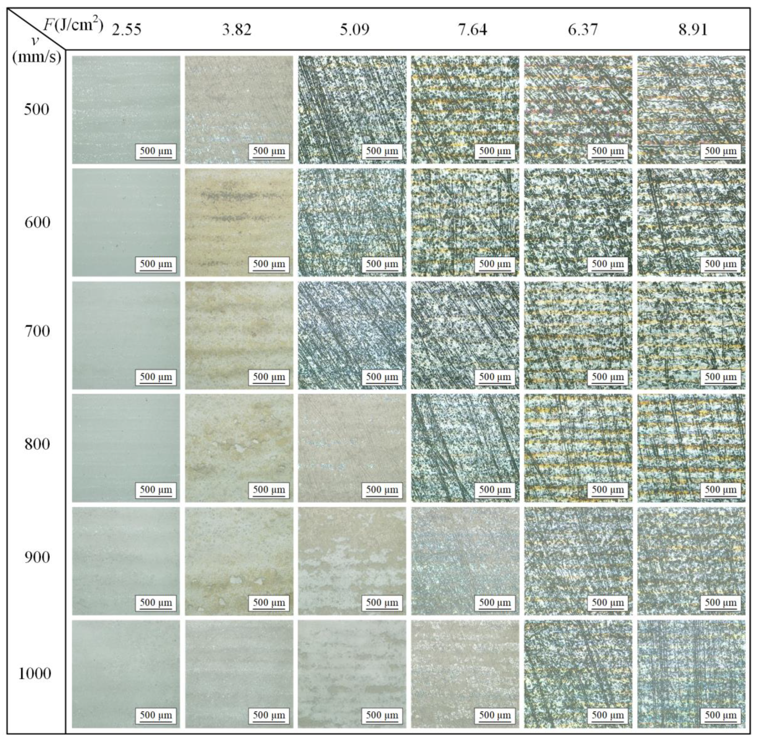
3.1. Macroscopic Observation

Figure 3 characterizes the macro morphological changes of the aircraft skin surfaces after laser cleaning at laser fluences of 2.55–8.91 J/cm2 and scanning speeds of 500–1000 mm/s. The paint on the skin surface decreased with the increase of laser fluence and the decrease in scanning speed. When the scanning speeds were 500–700 mm/s, the cleaned surfaces with laser fluences of 2.55 J/cm2 and 3.82 J/cm2 were covered with a large amount of residual paint, accompanied by obvious traces of laser action, while the paint was completely removed when the laser fluence increased to 5.09 J/cm2 and above. The surfaces from which the paint had been completely removed had both the texture of mechanical lapping Al alloy substrate and the traces of ablation to varying degrees. When the scanning speed was 800 mm/s, the surface with laser fluence of 5.09 J/cm2 began to expose the substrate, and the surface paint with laser fluences of 6.37–8.91 J/cm2 was completely cleaned. When the scanning speed was increased to 900–1000 mm/s, the Al alloy substrate began to expose with laser fluence of 6.37 J/cm2, and the surface paint with laser fluences of 7.64 J/cm2 and 8.91 J/cm2 was completely removed. It can be seen intuitively from the Figure 3 that the texture of mechanical lapping is clear at the initial stage of all paint peeling. Along with the further increase of laser fluence and the further decrease of scanning speed, the texture of substrate gradually disappeared, while the ablative crater formed by the recoil pressure of the metal vapor and the multiple yellow oxidized stripes caused by heat accumulation appeared on the surface during the laser cleaning [41,42].

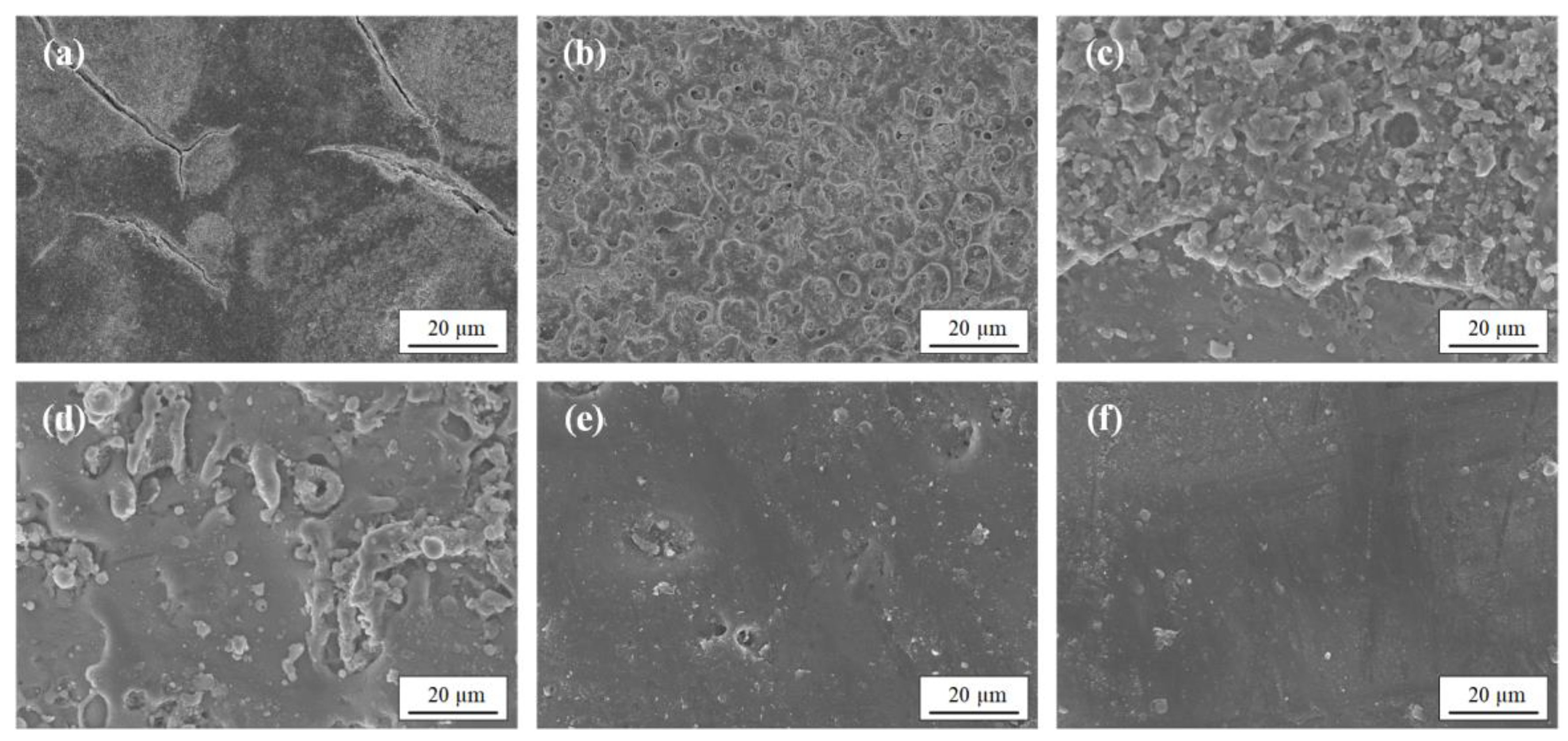
3.2. Microscopic Characterization

According to the abovementioned research results, five representative samples were selected for further comparative analysis with the original sample. The process parameters used for cleaning the samples are listed in Table 3. Figure 4 shows the micromorphology of the uncleaned and laser-cleaned aircraft skin surface obtained by SEM. It can be seen from Figure 4a that white areas were distributed on the untreated surface of sample 1, and fine cracks appeared in and around the white areas, which is due to the damage of the paint in the harsh environment during the service of the aircraft skin. After laser cleaning, the paint on the surface of sample 2 in Figure 4b still covered the entire substrate surface, and dense ablative pits appeared on the surface. With the increase of laser energy, a small part of substrate was exposed on the surface of sample 3 in Figure 4c. As the paint kept thinning under the action of the laser, the texture of the metal substrate began to appear on the surface, and it can be seen that there was an obvious demarcation line between the paint and the substrate. Figure 4d displays that almost of the paint on the surface of sample 4 was removed and exposed a large area of the substrate, with a smattering paint and oxide film remaining on the surface that were closely attached to the substrate. The paint on the surface of sample 5 was completely removed, while the texture on the surface of the substrate was clear and densely distributed (Figure 3). At the micro-scale, the paint on the surface of sample 5 in Figure 4e was absent, and the surface became flat. When the laser energy density further increased, there were obvious oxidation streaks on the surface of sample 6, and the substrate texture became sparse and shallow (Figure 3). Meanwhile, the observation area of sample 6 in Figure 4f is flatter than that of sample 5 in Figure 4e, indicating that the substrate of sample 6 was remelted under the action of the high-energy laser. In conclusion, it can be judged that within the research scope of this article, the cleaning effect of sample 5 was the best, and the corresponding process parameters were optimal.

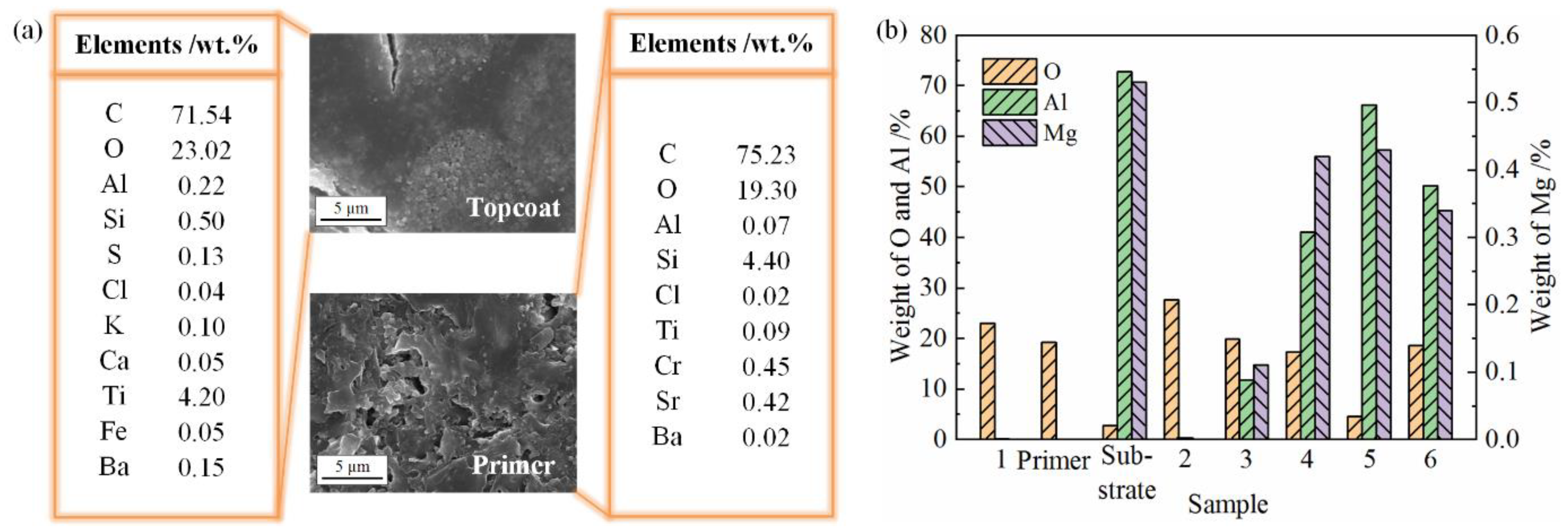
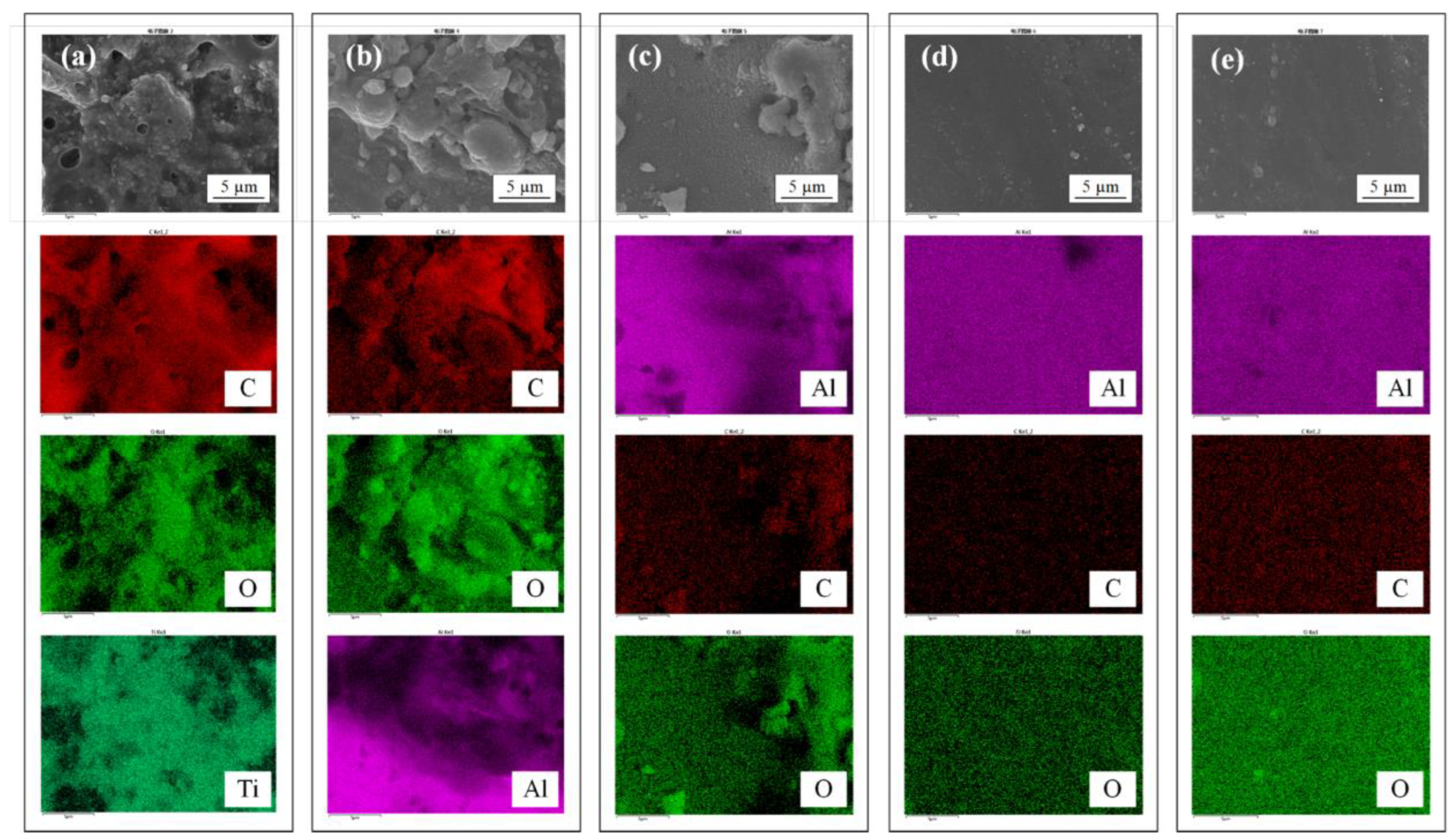
3.3. Energy Spectroscopy Analysis

The effect of laser cleaning varied greatly under different process parameters. EDS was used to analyze the elemental composition of the sample surfaces, and the measurement results are exhibited in Figure 5. For comparison with the changes of elements on the sample surfaces after laser cleaning, Figure 5a displays the chemical composition of the topcoat and primer. The main characteristic chemical components of the analyzed samples are shown in Figure 5b, where the Al alloy was acquired by mechanical rubbing of the original sample. Figure 6 presents the distribution diagrams of the first three elements with a large atomic percentage. The exposed paint of sample 2 was topcoat. Comparing the EDS results of sample 1 and sample 2 in Figure 5b, it can be found that there was little difference in weight of the elements. Through the morphology observation, the residual substances on the surface of sample 3 were primer and oxide film. Upon comparison with the EDS results of the primer, the changes were a significant increase in the content of Al to 11.76% and the presence of Mg elements at 0.11%. Furthermore, in Figure 6b, the content of Al element was greater, which was distributed in the lower left of sample 3 surface, which proves that the lower-left area of the surface was Al alloy substrate. The substances remaining on the surface of sample 4 were the primer and oxide film as those on sample 3. Compared with sample 3, the content of Al and Mg increased greatly, indicating that the Al alloy substrate accounted for a larger proportion in the surface-measurement area and less primer remained on the surface. From the Al element distribution diagram, the Al element was mainly distributed in the left half of the surface (Figure 6c). The EDS results of sample 5 suggest that the elements of the paint almost disappeared (Figure 5a), but a very small amount of paint splashed during the cleaning process and remained on the surface. The Al content of sample 5 increased significantly relative to that of sample 4 (Figure 5b) and was evenly distributed on the entire surface (Figure 6d), revealing that the paint had been completely removed and the substrate was fully exposed. The EDS comparison results between sample 5 and Al alloy substrate displayed that the content of O in sample 5 increased by 1.79%, while the content of Al and Mg elements decreased by 6.65% and 0.1%, respectively. It can be concluded that the surface of sample 5 was inevitably affected by laser heat accumulation, resulting in slight oxidation. In Figure 6e, the elements of Al and O were uniformly distributed on the surface of sample 6, indicating that the paint was thoroughly stripped. Nevertheless, according to the EDS results of sample 6, compared with sample 5, the content of O was further increased to 18.54%, while the elements of Al and Mg both decreased slightly, which proves that the thermal oxidation degree was higher. The above results can demonstrate that the cleaning effect of sample 5 was optimum, which is consistent with the results obtained from the microscopic characterization.

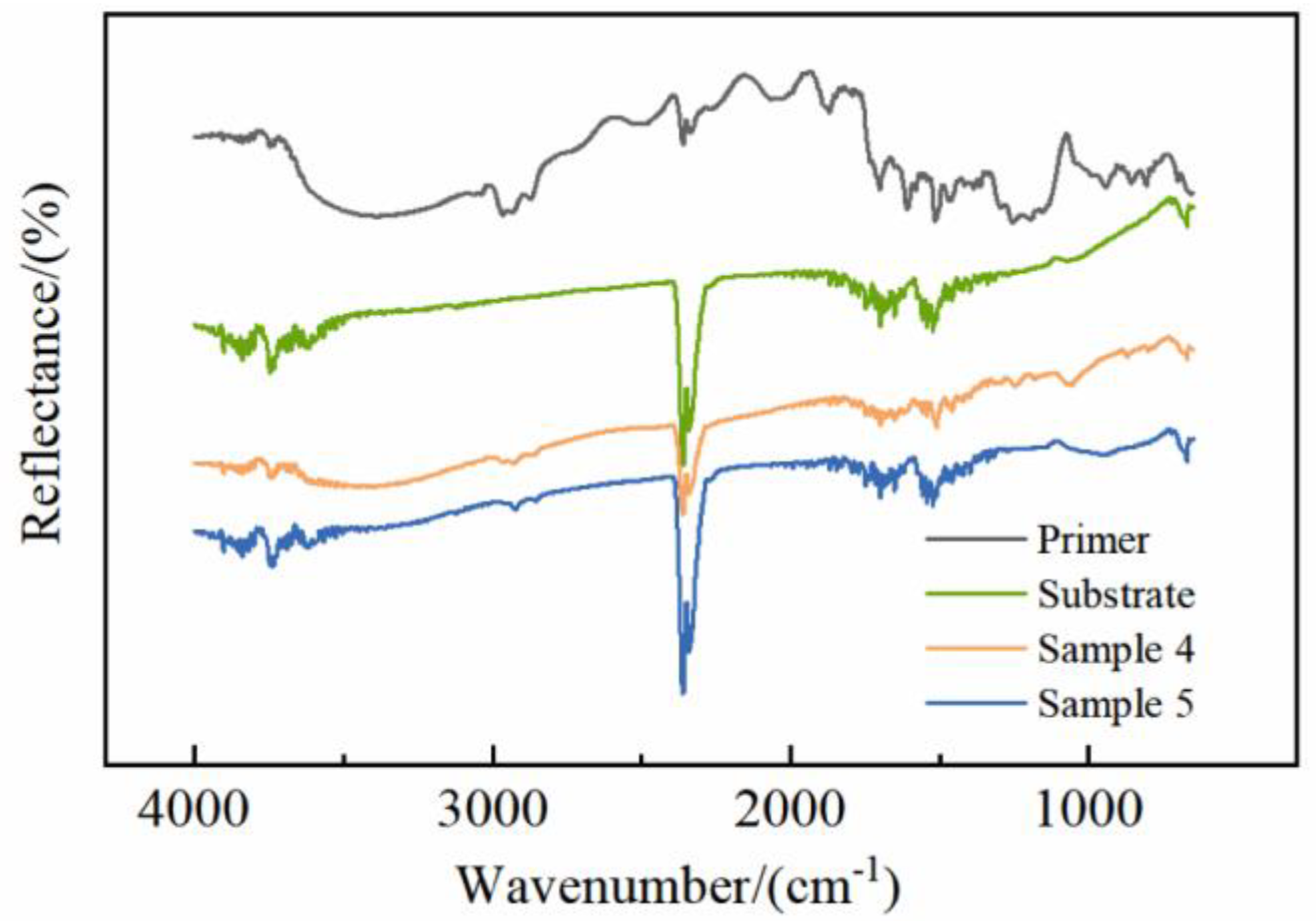
3.4. Fourier Transform Infrared Spectroscopy Analysis

Figure 7 collects the FTIR spectroscopy of the primer, the substrate treated by mechanical lapping, sample 4 with a small amount of adhesion on the surface, and sample 5 with the paint completely removed. The FTIR spectroscopy of the samples changed significantly with the paint-stripping degree. The broadband of the primer spectrum at 3600–3100 cm−1 corresponds to the O-H stretching vibration from hydroxyl group in the epoxy resin. After laser cleaning, the broadband intensity of sample 4 spectrum was significantly reduced, while the broadband of sample 5 spectrum disappeared. The peak of the primer at 3057 cm−1 was assigned to the C-H stretching vibration from the oxirane group, which did not exist in the spectrums of sample 4 and sample 5. The peaks induced by C-H stretching vibration of CH2 and CH aromatic and aliphatic at 2965 cm−1 and 2930 cm−1 became extremely weak after laser cleaning. Meanwhile, the peaks at 1608 cm−1, 1040 cm−1, 915 cm−1, 857 cm−1, and 770 cm−1 were induced by C=C stretching of aromatic rings, C-O-C stretching of ethers, C-O stretching and C-O-C stretching of the oxirane group, and CH2 rocking vibration, respectively, also disappeared completely after laser cleaning. Nevertheless, a few paint particles splashed on the surface during cleaning may result in faint characteristic peaks at certain wavenumbers. The spectrum of sample 5 tended to be consistent with that of substrate, indicating that the paint on the surface of sample 5 was completely removed after laser cleaning, which further verifies the conclusion of morphology and EDS. Accordingly, laser cleaning has the ability to non-selectively break the chemical bonds of the paint for removal.

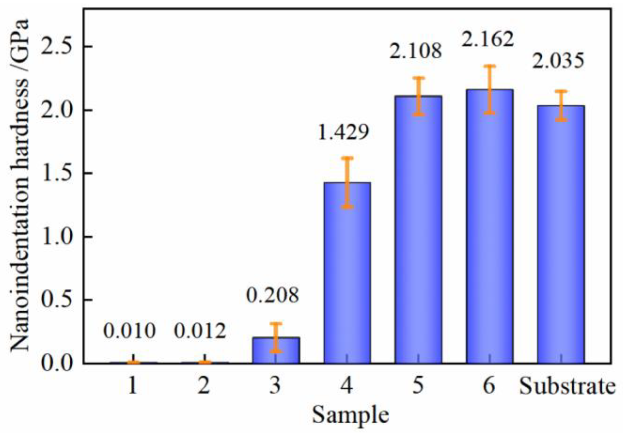
3.5. Nanoindentation Hardness Analysis

The change of surface microstructure caused by laser interaction with the sample may have an impact on the mechanical properties of Al alloy substrate [43,44,45], which needs further study. The nanoindentation hardness of laser-cleaned samples and Al alloy substrate obtained by mechanical lapping is shown in Figure 8. The paint exposed on the surfaces of sample 1 and sample 2 is both topcoat and fully covered the substrate, so the difference in hardness between the two samples was minimal, and the hardness values were very small. For sample 3, the paint adhered to majority of the Al alloy substrate, and the exposure of a small portion of the substrate resulted in an increase in hardness relative to sample 1 and sample 2. The hardness of Al alloy was greater than that of primer, so the hardness of sample 4, which exposes most of the substrate, greatly increased concerning that of sample 3. It should be noted that the uneven distribution of paint on the surfaces of sample 3 and sample 4 led to different microhardnesses at different positions, thereby resulting in a larger standard deviation of the microhardness. The paint of sample 5 and sample 6 was entirely stripped, and the hardness increased by 0.679 GPa and 0.733 GPa, respectively, compared with that of sample 4. The hardness of samples 5 and 6 increased by 3.587% and 6.241%, respectively, with respect to the substrate, indicating the formation of a hardened layer on the sample surface after laser cleaning.

4. Discussion

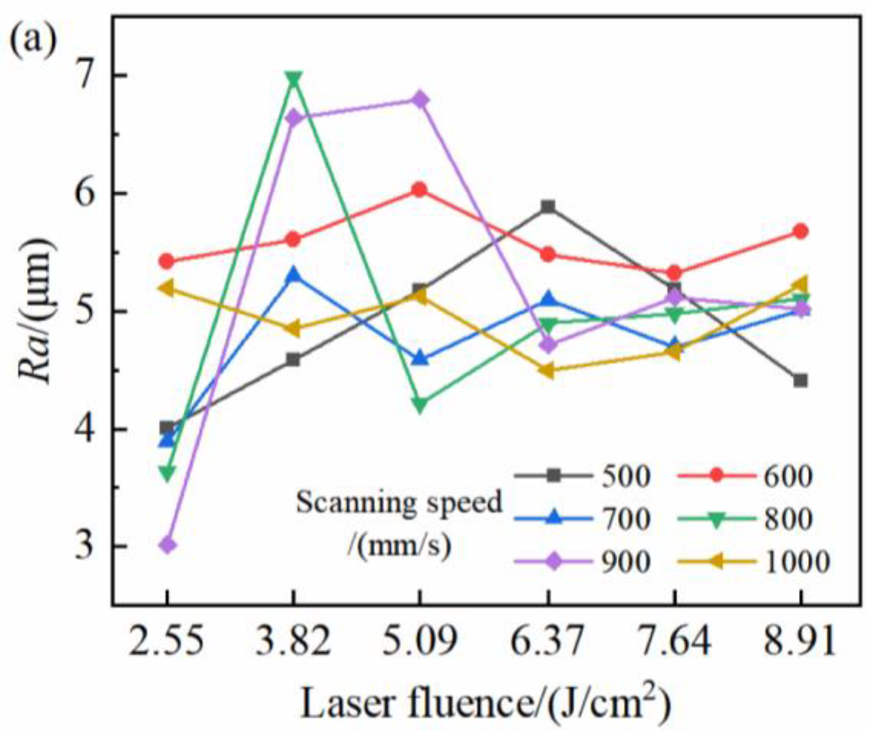
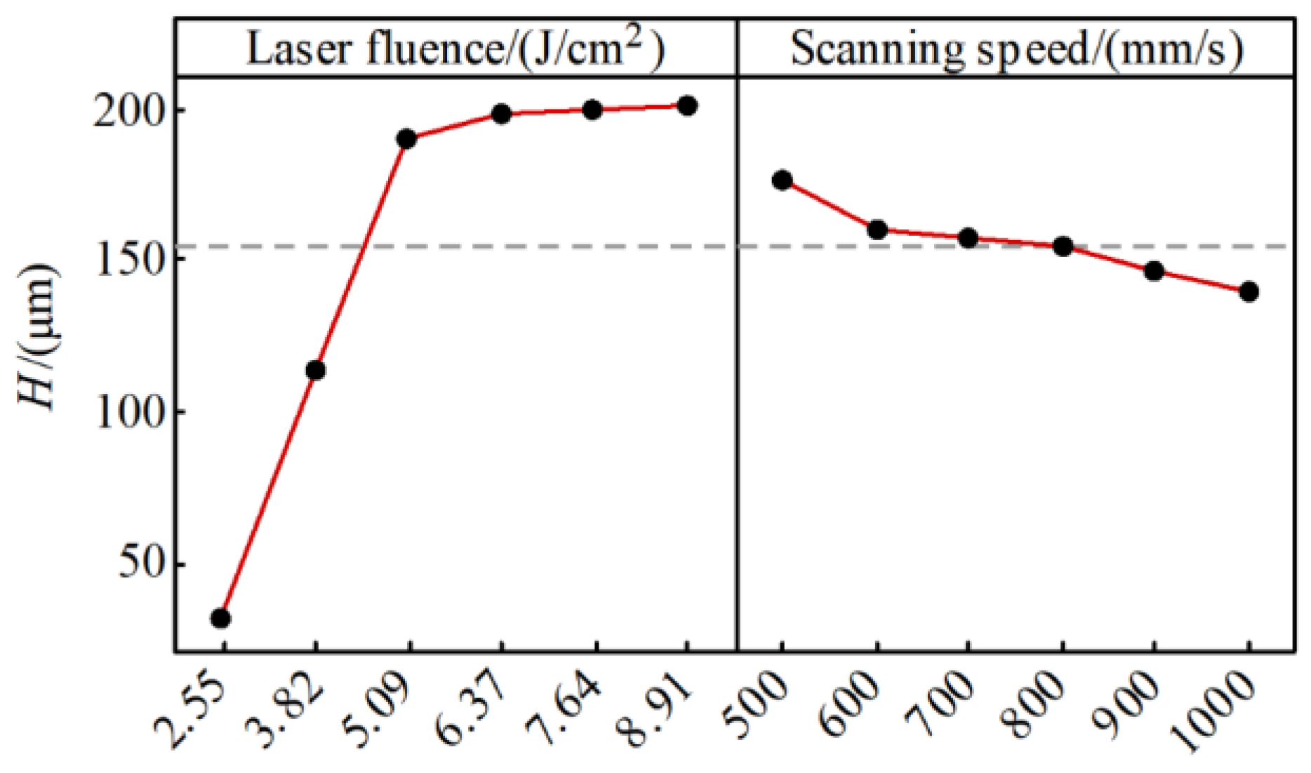
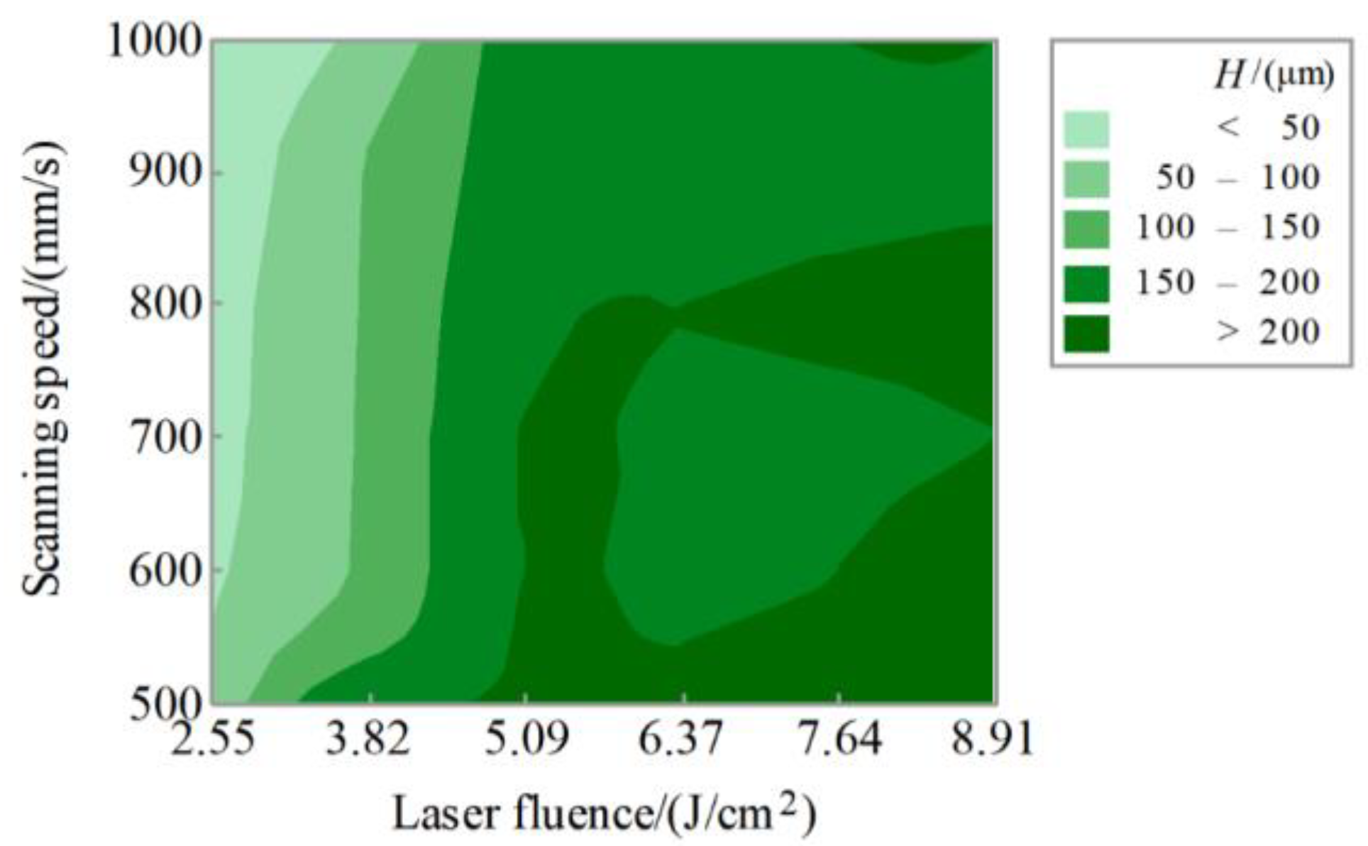
4.1. Influence of the Process Parameters on the Cleaning Effect

Ra is a considerable performance index of the quality of the machined surface, which reflects the micro-geometric error of the part surface, and greatly affects the working accuracy, corrosion resistance, and wear resistance of the parts [46,47,48]. H can directly represent the degree of laser cleaning. The Ra and H of the aircraft skin surface after laser cleaning at different process parameters are described in Figure 9 and analyzed in combination with Figure 3. When the laser fluence was 2.55 J/cm2, the laser energy was not great enough to peel off the thick topcoat at all scanning speeds within the range of research parameters, and H was small; thus, the exposed paint on the surfaces of the cleaned samples was still the topcoat that completely covered the samples. When the laser fluence increased to 3.82 J/cm2, the energy acting on the surface of the sample increased, and multiple layers of paints were exposed on the surface at the same time, resulting in a corresponding increase of Ra and H relative to that of the sample with the laser fluence of 2.55 J/cm2. When the laser fluences were 5.09–6.37 J/cm2, the paint of some samples was completely removed, the substrate texture was obvious, and the variation of the surface profile changed more greatly compared with that of the laser fluence of 2.55 J/cm2, so Ra increased and H reached the maximum. As the laser fluence continued to increase, the substrate texture of some samples became shallow or even disappeared. At this time, the surfaces were remelted and relatively flat, but the laser action time was so short that H did not change significantly. Form the whole, the surfaces of the samples that had not completely removed the paint and oxide film exposed a variety of objects to be cleaned at the same time, which were unevenly distributed on the substrate, and the edge of the residual paint layer on some surfaces was tilted. The surface morphology is complex, and the contour fluctuated greatly, so Ra changed in a large range. The surface morphology of the samples with the substrate completely exposed was affected by the substrate texture and laser ablation traces; Ra fluctuated slightly within a certain range. The change of H was relatively regular, which increased with the increase of laser fluence and the decrease of scanning speed. When the paint and oxide film were completely stripped, the changes of process parameters within the studied range did not cause a significant change in H. It is appropriate to evaluate the cleaning effect in consideration of the variation in Ra and H.
Analysis of variance was used to test the significance of the process parameters to the response [49,50]. Table 4 shows the results of the analysis of variance, and the p-value represents the degree of significance. For Ra, the p-value of the laser fluence was less than 0.05, and the p-value of the scanning speed was greater than 0.05, indicating that within the parameters of this study, laser fluence had a significant effect on Ra, while scanning speed had no significant effect on Ra. For H, the p-values of laser fluence and the scanning speed were both less than 0.05, signifying that the two process parameters had significant effects on H. To compare the degree of influence of laser fluence and scanning speed on H, the main effects analysis of H was carried out [51], and the results are shown in Figure 10. The lines drawn by the mean value of H at different levels of process parameters were not parallel to the X-axis, meaning that different levels of process parameters had different effects on H, and the fluctuation of laser fluence was significantly greater than that of scanning speed, so the influence of laser fluence on H was greater than that of scanning speed. Figure 11 draws the contour plot of H, which can intuitively observe the relationship between the response and the process parameters. Due to the thickness error during the painting process, the H of paint and the completely removed oxide film samples fluctuated around 200~202 µm. Within the parameters studied in this paper, the H of the samples with the substances completely removed from the substrate surface was mainly concentrated in the medium and high values of the laser fluence and the medium and low values of the scanning speed, but excessive laser fluence or too-small scanning speeds may cause serious oxidation of the substrate. Therefore, it is recommended to choose parameters in the middle region of laser fluence and scanning speed for laser paint stripping within the studied parameters.

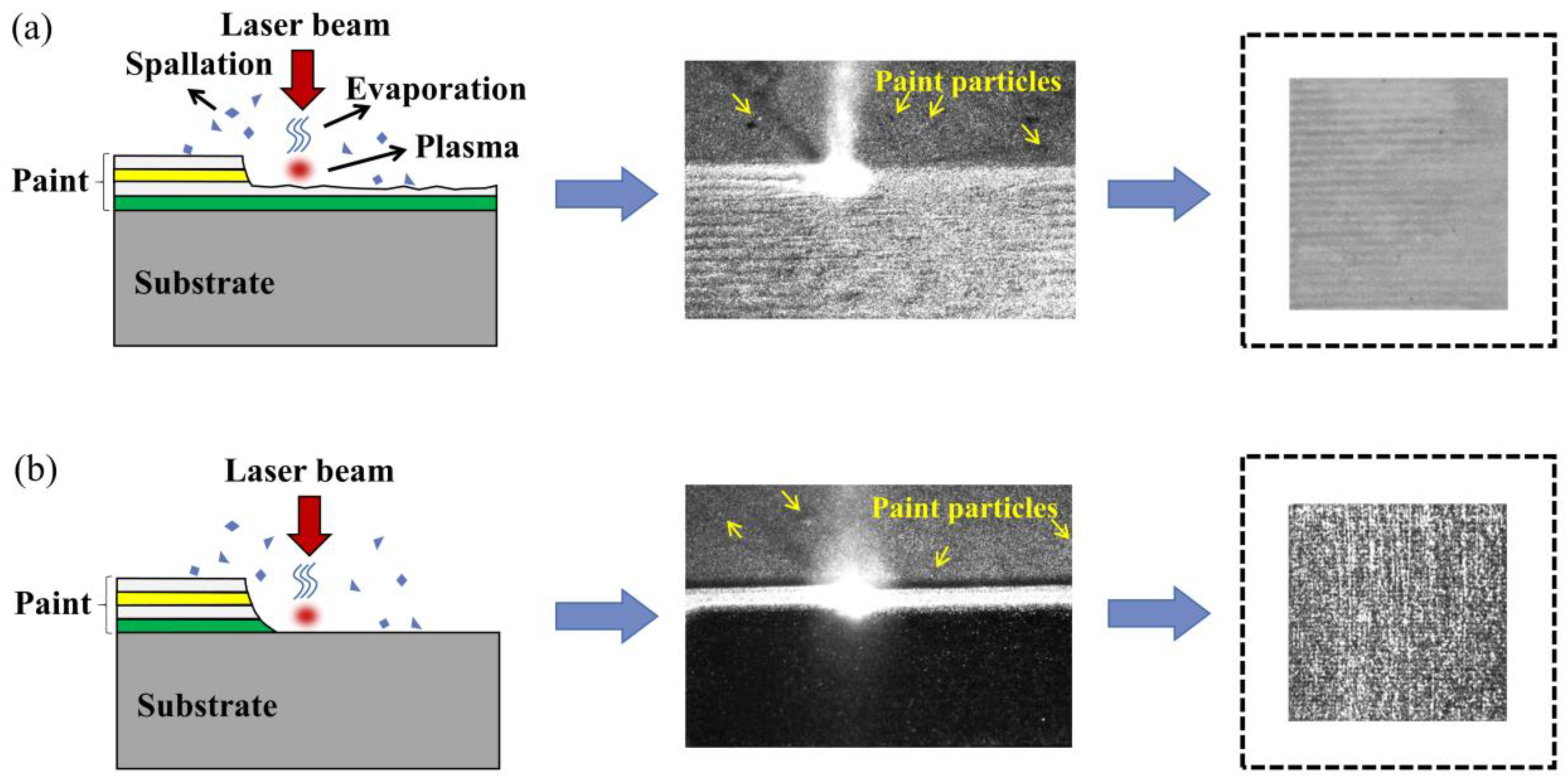
4.2. Mechanisms of Laser Paint Stripping from Aircraft Al Alloy Skin

Laser-cleaning technology is able to remove different substances from the surface of a variety of substrates and has become an environmentally friendly and advanced cleaning technology. Laser-cleaning processes are complex and varied. The bond or bonding force between the removed material and the substrate is destroyed through the action of light or heat, and the contaminants on the surface of substrate are removed by the physical and chemical reactions such as vaporization, thermal decomposition, vibration, and phase explosion [9,52,53]. For laser paint stripping, after the laser irradiates the paint surface, the paint absorbs the laser energy, then the temperature of the surface rises instantly, and the paint is thermally decomposed. When the temperature reaches and exceeds the boiling point of the paint, the paint will be vaporized. In the meantime, plasma is generated on the surface at a high temperature, and the plasma shock wave breaks the paint into pieces and ejects them into the air. Figure 12 describes the main schematic diagram of the laser paint-stripping mechanisms. The combined effect of multiple mechanisms eventually caused the paint layer to break away from the substrate. As shown in Figure 12a, the laser energy was low, part of the paint acted with the laser, and the ablation flame was obvious. As can be seen from Figure 12b, all the paint was affected by the laser under the action of high laser energy, the plasma cloud became larger, and the plasma-shock effect was notable. Furthermore, the tiny paint particles spattered were captured by the high-speed camera. The results showed that the cleaning mechanisms involved in laser paint stripping mainly included thermal decomposition, vaporization, and spallation.

4.3. Enhancement Mechanism of Microhardness Induced by Laser

EBSD analysis for the cross-sections of samples after mechanical lapping and laser cleaning were performed to observe the changes in the substrate grains. Figure 13 expresses the inverse pole figure (IPF) mappings and local misorientation (LM) mappings of the samples after mechanical lapping and laser cleaning. Comparing the IPF maps of the two samples in Figure 13a,b, grain refinement was not detected on the laser-cleaned surface, but an obvious color variation within the grains was observed on the near-surface after laser cleaning, indicating that the laser caused in the deformation of the grains. The LM maps of Figure 13c,d calculate the average dislocation between the target point and all its neighbors, characterizing the internal microstructure evolution. The LM of the laser-cleaned near-surface was significantly greater than that after mechanical treatment, and the LM distribution inside the grains of the samples after laser cleaning was evident, which further proves that laser cleaning induced obvious plastic deformation, thereby increasing the LM density. The surface microhardness of the sample with the paint completely removed by laser cleaning was higher than that of the sample with the paint completely removed by mechanical lapping, which can be attributed to the plastic deformation of the near-surface of the substrate caused by the shock wave generated during the laser paint stripping, resulting in strain hardening [37,54,55].

5. Conclusions

In this work, nanosecond-pulsed laser equipment was used to directly remove the multi-layer paint on the aluminum alloy skin of a Boeing series aircraft. The cleaning effect at different laser fluences and scanning speeds was studied, the surface morphology and chemical composition of uncleaned and cleaned samples were analyzed, and the nanoindentation hardness was discussed to explore the effect of laser on the substrate, which can contribute to the application of laser cleaning in aircraft maintenance. The main results are as follows.
(1) Nanosecond-pulsed lasers can effectively clean the multi-layer paint on the aircraft skin. When the laser fluence and scanning speed were 5.09 J/cm2 and 700 mm/s, respectively, the substrate texture was clear and the FTIR spectrum could not detect the vibration-induced peaks of the groups contained in the paint, but the content of the O element on the surface of the sample increased by 1.790% relative to the mechanically treated aluminum alloy, which proves that the samples cleaned at this parameters have the best cleaning effect and avoid causing damage to the aluminum alloy substrate, but inevitably suffer from a slight laser thermal influence.
(2) After the laser acts on the aircraft skin, a large number of dislocations were generated within the grains on the near-surface, which means that the surface underwent plastic deformation, producing a strain hardening layer on the substrate, and the surface with paint completely stripped and undamaged had a 3.587% increase in nanoindentation hardness compared with the traditional mechanical lapping sample.
(3) Nanosecond-pulsed lasers can effectively strip the paint on the surface of aircraft Al alloy skin, and the mechanisms mainly include thermal decomposition, evaporation, and spallation.
(4) The variety of paint layers led to intricate surface morphology after laser stripping, resulting in complex changes in Ra and H. The combined analysis of Ra and H can be used to evaluate the cleaning effect and also provides guidance for the selection of parameters for laser cleaning. The successful removal of paint on aircraft skin by laser is of great significance for the application of laser cleaning in aircraft maintenance.

Author Contributions

Conceptualization, J.X. and B.G.; Data curation, W.L. and X.S.; Formal analysis, W.L. and J.G.; Funding acquisition, J.X. and B.G.; Investigation, W.L., X.S. and Y.J.; Methodology, W.L., X.S. and J.G.; Project administration, Y.J., J.X. and B.G.; Resources, J.X. and B.G.; Software, W.L. and X.S.; Supervision, Y.J., J.X. and B.G.; Visualization, J.G.; Writing—original draft, W.L.; Writing—review & editing, W.L. and X.S. All authors have read and agreed to the published version of the manuscript.

Funding

This research was funded by the Guangdong Province Key Area R&D Program under Grant No. 2018B090905003, and the National Natural Science Foundation of China under Grant No. U19A2077.

Institutional Review Board Statement

Not applicable.

Informed Consent Statement

Not applicable.

Data Availability Statement

Not applicable.

Conflicts of Interest

The authors declare no conflict of interest.

References

  1. Starke, E.A.; Staley, J.T. Application of Modern Aluminum Alloys to Aircraft. Prog. Aerosp. Sci. 1996, 32, 131–172. [Google Scholar] [CrossRef]
  2. Molina-Viedma, Á.; López-Alba, E.; Felipe-Sesé, L.; Díaz, F. Full-Field Operational Modal Analysis of an Aircraft Composite Panel from the Dynamic Response in Multi-Impact Test. Sensors 2021, 21, 1602. [Google Scholar] [CrossRef] [PubMed]
  3. Moupfouma, F. Aircraft Structure Paint Thickness and Lightning Swept Stroke Damages. SAE Int. J. Aerosp. 2013, 6, 392–398. [Google Scholar] [CrossRef]
  4. Merati, A.; Yanishevsky, M.; Despinic, T.; Lo, P. The Effect of Atmospheric Plasma Paint Stripping on the Fatigue Crack Growth Properties of Aluminium Substrates. JMMCE 2017, 5, 161–173. [Google Scholar] [CrossRef] [Green Version]
  5. Merati, A.; Yanishevsky, M.; Despinic, T.; Lo, P.; Pankov, V. Alternate Environmentally Friendly De-Painting Process for Aircraft Structures-Atmospheric Plasma. JMMCE 2017, 5, 223–235. [Google Scholar] [CrossRef] [Green Version]
  6. Yanishevsky, M.; Merati, A.; Bombardier, Y. Effect of Atmospheric Plasma Paint Removal on the Fatigue Performance of 2024-T3 Aluminium Alloy Sheet. J. Miner. Mater. Charact. Eng. 2017, 6, 15–24. [Google Scholar] [CrossRef] [Green Version]
  7. Shan, T.; Yin, F.; Wang, S.; Qiao, Y.; Liu, P. Surface Integrity Control of Laser Cleaning of an Aluminum Alloy Surface Paint Layer. Appl. Opt. 2020, 59, 9313–9319. [Google Scholar] [CrossRef]
  8. Morelli, U.; Dalla Vedova, M.D.L.; Maggiore, P. Automatic Painting and Paint Removal System: A Preliminary Design for Aircraft Applications. In Proceedings of the Advances in Service and Industrial Robotics, Patras, Greece, 19–21 June 2018; Springer: Cham, Switzerland, 2019; pp. 640–650. [Google Scholar]
  9. Li, X.; Wang, H.; Yu, W.; Wang, L.; Wang, D.; Cheng, H.; Wang, L. Laser Paint Stripping Strategy in Engineering Application: A Systematic Review. Optik 2021, 241, 167036. [Google Scholar] [CrossRef]
  10. Uang, S.-N.; Shih, T.-S.; Chang, C.-H.; Chang, S.-M.; Tsai, C.-J.; Deshpande, C.G. Exposure Assessment of Organic Solvents for Aircraft Paint Stripping and Spraying Workers. Sci. Total Environ. 2006, 356, 38–44. [Google Scholar] [CrossRef]
  11. Yang, W.; Qian, Z.; Cao, Y.; Wei, Y.; Fu, C.; Li, T.; Lin, D.; Li, S. LIBS Monitoring and Analysis of Laser-Based Layered Controlled Paint Removal from Aircraft Skin. J. Spectrosc. 2021, 2021, 1–12. [Google Scholar] [CrossRef]
  12. Sun, X.; Yu, Q.; Bai, X.; Jin, G.; Cai, J.; Yuan, B. Substrate Cleaning Threshold for Various Coated Al Alloys Using a Continuous-Wave Laser. Photonics 2021, 8, 395. [Google Scholar] [CrossRef]
  13. Tam, A.C.; Leung, W.P.; Zapka, W.; Ziemlich, W. Laser-cleaning Techniques for Removal of Surface Particulates. J. Appl. Phys. 1992, 71, 3515–3523. [Google Scholar] [CrossRef]
  14. Steen, W.M. Laser Material Processing—An Overview. J. Opt. A Pure Appl. Opt. 2003, 5, S3. [Google Scholar] [CrossRef]
  15. Kane, D.M. Laser Cleaning II; World Scientific: Singapore, 2007; ISBN 978-981-270-372-9. [Google Scholar]
  16. Steen, W.M.; Mazumder, J. Laser Material Processing; Springer: London, UK, 2010; ISBN 978-1-84996-061-8. [Google Scholar]
  17. Bertasa, M.; Korenberg, C. Successes and Challenges in Laser Cleaning Metal Artefacts: A Review. J. Cult. Herit. 2022, 53, 100–117. [Google Scholar] [CrossRef]
  18. Zhu, G.; Xu, Z.; Jin, Y.; Chen, X.; Yang, L.; Xu, J.; Shan, D.; Chen, Y.; Guo, B. Mechanism and Application of Laser Cleaning: A Review. Opt. Lasers Eng. 2022, 157, 107130. [Google Scholar] [CrossRef]
  19. Genna, S.; Lambiase, F.; Leone, C. Effect of Laser Cleaning in Laser Assisted Joining of CFRP and PC Sheets. Compos. Part B Eng. 2018, 145, 206–214. [Google Scholar] [CrossRef]
  20. Lu, Y.; Ding, Y.; Wang, M.; Yang, L.; Wang, Y. An Environmentally Friendly Laser Cleaning Method to Remove Oceanic Micro-Biofoulings from AH36 Steel Substrate and Corrosion Protection. J. Clean. Prod. 2021, 314, 127961. [Google Scholar] [CrossRef]
  21. Zhang, D.; Wu, L.-C.; Ueki, M.; Ito, Y.; Sugioka, K. Femtosecond Laser Shockwave Peening Ablation in Liquids for Hierarchical Micro/Nanostructuring of Brittle Silicon and Its Biological Application. Int. J. Extrem. Manuf. 2020, 2, 045001. [Google Scholar] [CrossRef]
  22. Zhang, D.; Ranjan, B.; Tanaka, T.; Sugioka, K. Underwater Persistent Bubble-Assisted Femtosecond Laser Ablation for Hierarchical Micro/Nanostructuring. Int. J. Extrem. Manuf. 2020, 2, 015001. [Google Scholar] [CrossRef]
  23. Schaiwlow, A.L. Lasers. Science 1965, 149, 13–22. [Google Scholar] [CrossRef]
  24. Bedair, S.M.; Smith, H.P. Atomically Clean Surfaces by Pulsed Laser Bombardment. J. Appl. Phys. 1969, 40, 4776–4781. [Google Scholar] [CrossRef]
  25. Pozo-Antonio, J.S.; Ramil, A.; Rivas, T.; López, A.J.; Fiorucci, M.P. Effectiveness of Chemical, Mechanical and Laser Cleaning Methods of Sulphated Black Crusts Developed on Granite. Constr. Build. Mater. 2016, 112, 682–690. [Google Scholar] [CrossRef]
  26. Yang, J.; Zhou, J.; Sun, Q.; Meng, X.; Guo, Z.; Zhu, M. Digital Analysis and Prediction of the Topography after Pulsed Laser Paint Stripping. J. Manuf. Process. 2021, 62, 685–694. [Google Scholar] [CrossRef]
  27. Ouyang, J.; Mativenga, P.T.; Liu, Z.; Li, L. Energy Consumption and Process Characteristics of Picosecond Laser De-Coating of Cutting Tools. J. Clean. Prod. 2021, 290, 125815. [Google Scholar] [CrossRef]
  28. Zhuang, S.; Kainuma, S.; Yang, M.; Haraguchi, M.; Asano, T. Characterizing Corrosion Properties of Carbon Steel Affected by High-Power Laser Cleaning. Constr. Build. Mater. 2021, 274, 122085. [Google Scholar] [CrossRef]
  29. Kumar, A.; Biswas, D.J. Particulate Size and Shape Effects in Laser Cleaning of Heavy Metal Oxide Loose Contamination off Clad Surface. Opt. Laser Technol. 2018, 106, 286–293. [Google Scholar] [CrossRef]
  30. Palomar, T.; Oujja, M.; Llorente, I.; Ramírez Barat, B.; Cañamares, M.V.; Cano, E.; Castillejo, M. Evaluation of Laser Cleaning for the Restoration of Tarnished Silver Artifacts. Appl. Surf. Sci. 2016, 387, 118–127. [Google Scholar] [CrossRef] [Green Version]
  31. Yoo, H.J.; Baek, S.; Kim, J.H.; Choi, J.; Kim, Y.-J.; Park, C. Effect of Laser Surface Cleaning of Corroded 304L Stainless Steel on Microstructure and Mechanical Properties. J. Mater. Res. Technol. 2022, 16, 373–385. [Google Scholar] [CrossRef]
  32. Li, Z.; Chen, X.; Yang, S.; Zhang, D.; Xu, J.; Ma, R.; Shan, D.; Guo, B. Removal Mechanism of Liquid-Assisted Nanosecond Pulsed Laser Cleaning TA15 Titanium Alloy Oxide Film. J. Mater. Res. Technol. 2022, 19, 4986–4997. [Google Scholar] [CrossRef]
  33. Tian, Z.; Lei, Z.; Chen, X.; Chen, Y.; Zhang, L.-C.; Bi, J.; Liang, J. Nanosecond Pulsed Fiber Laser Cleaning of Natural Marine Micro-Biofoulings from the Surface of Aluminum Alloy. J. Clean. Prod. 2020, 244, 118724. [Google Scholar] [CrossRef]
  34. Tsunemi, A.; Endo, A.; Ichishima, D. Paint Removal from Aluminum and Composite Substrate of Aircraft by Laser Ablation Using TEA CO2 Lasers; Proc. SPIE, High-Power Laser Ablation, Santa Fe, NM, United States, 26–30 April 1998; Phipps, C.R., Ed.; SPIE: Bellingham, WA, USA, 1998; pp. 1018–1022. [Google Scholar]
  35. Arthur, J. Robotic Laser System to Strip Paint from Aircraft. Adv. Coat. Surf. Technol. 2013, 26, 2–3. [Google Scholar]
  36. Wang, F.; Wang, Q.; Huang, H.; Cheng, Y.; Wang, L.; Ai, S.; Cai, C.; Chen, H. Effects of Laser Paint Stripping on Oxide Film Damage of 2024 Aluminium Alloy Aircraft Skin. Opt. Express OE 2021, 29, 35516–35531. [Google Scholar] [CrossRef] [PubMed]
  37. Zhu, G.; Wang, S.; Cheng, W.; Ren, Y.; Wen, D. Corrosion and Wear Performance of Aircraft Skin after Laser Cleaning. Opt. Laser Technol. 2020, 132, 106475. [Google Scholar] [CrossRef]
  38. Dutta Majumdar, J.; Manna, I. Laser Material Processing. Int. Mater. Rev. 2011, 56, 341–388. [Google Scholar] [CrossRef]
  39. Razab, M.K.A.A.; Mohamed Noor, A.; Suhaimi Jaafar, M.; Abdullah, N.H.; Suhaimi, F.M.; Mohamed, M.; Adam, N.; Auli Nik Yusuf, N.A. A Review of Incorporating Nd: YAG Laser Cleaning Principal in Automotive Industry. J. Radiat. Res. Appl. Sci. 2018, 11, 393–402. [Google Scholar] [CrossRef] [Green Version]
  40. Kuang, Z.; Guo, W.; Li, J.; Jin, Y.; Qian, D.; Ouyang, J.; Fu, L.; Fearon, E.; Hardacre, R.; Liu, Z.; et al. Nanosecond Fibre Laser Paint Stripping with Suppression of Flames and Sparks. J. Mater. Process. Technol. 2019, 266, 474–483. [Google Scholar] [CrossRef]
  41. Shi, T.; Wang, C.; Mi, G.; Yan, F. A Study of Microstructure and Mechanical Properties of Aluminum Alloy Using Laser Cleaning. J. Manuf. Process. 2019, 42, 60–66. [Google Scholar] [CrossRef]
  42. Wang, Z.; Zeng, X.; Huang, W. Parameters and Surface Performance of Laser Removal of Rust Layer on A3 Steel. Surf. Coat. Technol. 2003, 166, 10–16. [Google Scholar] [CrossRef]
  43. Zhu, G.; Wang, S.; Cheng, W.; Wang, G.; Liu, W.; Ren, Y. Investigation on the Surface Properties of 5A12 Aluminum Alloy after Nd: YAG Laser Cleaning. Coatings 2019, 9, 578. [Google Scholar] [CrossRef] [Green Version]
  44. Mahanty, S. Gouthama Surface Modification of Al–Si Alloy by Excimer Laser Pulse Processing. Mater. Chem. Phys. 2016, 173, 192–199. [Google Scholar] [CrossRef]
  45. Saklakoglu, N.; Gencalp Irizalp, S.; Akman, E.; Demir, A. Near Surface Modification of Aluminum Alloy Induced by Laser Shock Processing. Opt. Laser Technol. 2014, 64, 235–241. [Google Scholar] [CrossRef]
  46. Ge, J.; Liu, H.; Yang, S.; Lan, J. Laser Cleaning Surface Roughness Estimation Using Enhanced GLCM Feature and IPSO-SVR. Photonics 2022, 9, 510. [Google Scholar] [CrossRef]
  47. Khorasani, A.M.; Yazdi, M.R.S.; Safizadeh, M.S. Analysis of Machining Parameters Effects on Surface Roughness: A Review. IJCMSSE 2012, 5, 68. [Google Scholar] [CrossRef]
  48. Li, Z.; Xu, J.; Zhang, D.; Xu, Z.; Su, X.; Jin, Y.; Shan, D.; Chen, Y.; Guo, B. Nanosecond Pulsed Laser Cleaning of Titanium Alloy Oxide Films: Modeling and Experiments. J. Manuf. Process. 2022, 82, 665–677. [Google Scholar] [CrossRef]
  49. Larson, M.G. Analysis of Variance. Circulation 2008, 117, 115–121. [Google Scholar] [CrossRef] [Green Version]
  50. Gelman, A. Analysis of Variance—Why It Is More Important than Ever. Ann. Stat. 2005, 33, 1–53. [Google Scholar] [CrossRef] [Green Version]
  51. Finney, D.J. Main Effects and Interactions. J. Am. Stat. Assoc. 1948, 43, 566–571. [Google Scholar] [CrossRef]
  52. Zhang, D.; Xu, J.; Li, Z.; Li, K.; Wang, C.; Shan, D.; Guo, B. Removal Mechanism of Blue Paint on Aluminum Alloy Substrate during Surface Cleaning Using Nanosecond Pulsed Laser. Opt. Laser Technol. 2022, 149, 107882. [Google Scholar] [CrossRef]
  53. Zhang, D.; Xu, J.; Li, Z.; Jin, Y.; Su, X.; Shan, D.; Guo, B. Removal Mechanisms of Nanosecond Pulsed Laser Cleaning of Blue and Red Polyurethane Paint. Appl. Phys. A 2022, 128, 170. [Google Scholar] [CrossRef]
  54. Liu, K.K.; Hill, M.R. The Effects of Laser Peening and Shot Peening on Fretting Fatigue in Ti–6Al–4V Coupons. Tribol. Int. 2009, 42, 1250–1262. [Google Scholar] [CrossRef]
  55. Jing, Y.; Fang, X.; Xi, N.; Feng, X.; Huang, K. Investigation of Microstructure and Mechanical Properties Evolution in 7050 Aluminum Alloy and 316L Stainless Steel Treated by Laser Shock Peening. Mater. Charact. 2021, 182, 111571. [Google Scholar] [CrossRef]
Figure 1. Structure of Boeing aircraft skin: (a) cross-section observation of the skin, (b) EDS analysis of the skin cross-section.
Photonics 10 00096 g001
Figure 2. Schematic of laser-cleaning system and laser-cleaning scanning path.
Photonics 10 00096 g002
Figure 3. Macro morphology of aircraft skin surfaces after laser cleaning with different laser fluences and scanning speeds.
Photonics 10 00096 g003
Figure 4. Micromorphology of aircraft skin surfaces before and after laser cleaning: (a) untreated sample 1 and laser-cleaned (b) sample 2, (c) sample 3, (d) sample 4, (e) sample 5, and (f) sample 6.
Photonics 10 00096 g004
Figure 5. Chemical composition measurement results of sample surfaces obtained by EDS: (a) measurement results of chemical elements for topcoat and primer, (b) main characteristic chemical components of the observed samples.
Photonics 10 00096 g005
Figure 6. Distribution diagrams of the first three elements with the largest proportion on the laser-cleaned sample surface: (a) sample 2, (b) sample 3, (c) sample 4, (d) sample 5, (e) sample 6.
Photonics 10 00096 g006
Figure 7. FTIR spectroscopy of primer, substrate, and laser-cleaned sample 4 and sample 5.
Photonics 10 00096 g007
Figure 8. Comparison of the nanoindentation hardness of the laser-cleaned samples and substrate.
Photonics 10 00096 g008
Figure 9. Cleaning effect of the samples after laser cleaning at different process parameters: (a) surface roughness, (b) stripping thickness.
Photonics 10 00096 g009aPhotonics 10 00096 g009b
Figure 10. Main effects plot for stripping thickness.
Photonics 10 00096 g010
Figure 11. Contour plot of stripping thickness.
Photonics 10 00096 g011
Figure 12. Schematic diagram of laser paint-stripping mechanisms: (a) mechanisms for incompletely removing paint, (b) mechanisms for completely removing paint.
Photonics 10 00096 g012
Figure 13. IPF mappings for cross-sections of the (a) mechanical lapping sample and (b) laser-cleaned sample, and LM mappings for the cross-sections of the (c) mechanical lapping sample and (d) laser-cleaned sample.
Photonics 10 00096 g013
Table 1. Main parameters of the laser.
ParameterSymbolValueUnit
Wavelengthλ1064nm
Maximum average powerP1000W
Pulse durationτ30, 40, 60, 100ns
Repetition ratef2–50kHz
Laser spot diameterD1mm
Maximum scanning speedv10,000mm/s
Table 2. Design scheme of the experimental factors and levels.
LevelF (J/cm2)v (mm/s)
12.55500
23.82600
35.09700
46.37800
57.64900
68.911000
Table 3. The design scheme of the experimental factors and levels.
Sample NumberF (J/cm2)v (mm/s)
100
22.55500
35.09800
46.37900
55.09700
68.91700
Table 4. Analysis of variance for surface roughness and stripping thickness.
ResponseSourceDFAdj SSAdj MSp-Value
RaF57.1091.42180.046
Rav52.7250.54500.425
HF5145,15829,031.5<0.001
Hv54717943.30.019
Disclaimer/Publisher’s Note: The statements, opinions and data contained in all publications are solely those of the individual author(s) and contributor(s) and not of MDPI and/or the editor(s). MDPI and/or the editor(s) disclaim responsibility for any injury to people or property resulting from any ideas, methods, instructions or products referred to in the content.

