Article

Energy Management and Power Distribution for Battery/Ultracapacitor Hybrid Energy Storage System in Electric Vehicles with Regenerative Braking Control

by
Abdelsalam A. Ahmed
1,*,
Young Il Lee
2,
Saleh Al Dawsari
3,4,*,
Ahmed A. Zaki Diab
5,* and
Abdelsalam A. Ezzat
6
1
Electrical Power and Machines Engineering Department, Faculty of Engineering, Tanta University, Tanta 31527, Egypt
2
Electrical and Information Engineering, Seoul National University of Science and Technology, Seoul 01811, Republic of Korea
3
Electrical Engineering Department, College of Engineering, Najran University, Najran 1988, Saudi Arabia
4
Department of Electrical Engineering, College of Engineering, Northern Border University, Arar 73213, Saudi Arabia
5
Electrical Engineering Department, Faculty of Engineering, Minia University, Minia 61111, Egypt
6
El-Minia High Institute of Engineering and Technology, New Minya, Minia 61111, Egypt
*
Authors to whom correspondence should be addressed.
Math. Comput. Appl. 2025, 30(4), 82; https://doi.org/10.3390/mca30040082 (registering DOI)
Submission received: 14 April 2025 / Revised: 22 July 2025 / Accepted: 31 July 2025 / Published: 3 August 2025
(This article belongs to the Special Issue Applied Optimization in Automatic Control and Systems Engineering)

Abstract

This paper presents an advanced energy management system (EMS) for optimizing power distribution in a battery/ultracapacitor (UC) hybrid energy storage system (HESS) for electric vehicles (EVs). The proposed EMS accounts for all energy flow scenarios within a practical driving cycle. A regenerative braking control strategy is developed to maximize kinetic energy recovery using an induction motor, efficiently distributing the recovered energy between the UC and battery. Additionally, a power flow management approach is introduced for both motoring (discharge) and braking (charge) operations via bidirectional buck–boost DC-DC converters. In discharge mode, an optimal distribution factor is dynamically adjusted to balance power delivery between the battery and UC, maximizing efficiency. During charging, a DC link voltage control mechanism prioritizes UC charging over the battery, reducing stress and enhancing energy recovery efficiency. The proposed EMS is validated through simulations and experiments, demonstrating significant improvements in vehicle acceleration, energy efficiency, and battery lifespan.

1. Introduction

1.1. Related Works

Lithium-ion (Li-ion) batteries are the predominant energy storage solution for portable electronic devices and electric vehicles (EVs). Modern Li-ion battery technology focuses on balancing high cell voltage with other performance parameters, such as rate capability and cycle life [1]. However, Li-ion batteries alone face challenges in handling high-peak-power demands efficiently. Supercapacitors (SCs), also known as ultracapacitors (UCs), exhibit superior charge/discharge rate capability, making them suitable for compensating transient high-power demands when battery power is insufficient.
The combination of a battery and UC in a hybrid energy storage system (HESS) leverages the complementary advantages of both storage technologies. In such a configuration, UCs absorb rapid power fluctuations, thereby reducing stress on the battery and prolonging its operational lifespan. When integrated into EVs, the HESS facilitates effective storage of regenerative braking energy (RBE), which can be reused to enhance vehicle acceleration. Additionally, a well-optimized HESS improves overall vehicle performance by offering high energy density, long cycle life [2], and a significant reduction in system weight compared to a battery-only energy storage system.
In EV and hybrid electric vehicle (HEV) applications, a battery pack (BP) combined with an UC as a HESS provides superior power management and control flexibility compared to conventional stand-alone battery designs [3]. Various studies have explored different control methodologies for HESSs. For instance, a characterization method for UCs was presented in [4], where a control strategy for DC-bus voltage and current regulation in a BP/UC HESS was implemented using two buck–boost converters. An alternative approach employing a UC-only energy storage system (ESS) was proposed in [5], where a DC-DC converter was used to regulate power flow. Additionally, load-sharing strategies between the battery and UC have been explored in [3,4,5,6,7]. However, achieving maximum discharge efficiency in HESSs remains an area that has received limited research attention.
The economic viability of HESSs is particularly evident in municipal transportation systems, such as city transit buses, where regenerative braking plays a crucial role in improving energy efficiency [2,8,9]. Regenerative braking (RB) enables EVs and HEVs to recover kinetic energy by employing an electric traction motor to generate negative torque, converting kinetic energy into electrical energy that recharges the ESS [10]. However, conventional battery technologies impose limitations on RB due to their relatively low power density and charge acceptance rate. UCs, with their high specific power and extended cycle life, offer a promising solution for efficiently storing and utilizing RBE [11].
Several studies have proposed advanced control algorithms for optimizing regenerative breaking. In [12,13,14], the braking process was categorized into dissipative and regenerative modes. A slip speed control mechanism for induction motors (IMs) was introduced in [13,14] to maximize energy recovery by operating the motor in the negative slip region. Additionally, non-monotonic energy consumption behavior during battery discharge was examined in [15], where SCs were utilized to compensate for rapid energy fluctuations. Recent advancements in model predictive control (MPC) techniques have further improved HESS performance. The authors in [16] proposed an MPC-based control strategy for three-level bidirectional DC-DC converters in a DC microgrid, ensuring voltage regulation and minimizing system current ripple. In [17], an MPC-based approach was also introduced to optimize energy distribution in a HESS for EVs. A two-loop control framework was implemented, consisting of an inner predictive current controller and an outer voltage control loop, which efficiently allocated low-frequency power variations to the battery while managing high-frequency power fluctuations using SCs.
Moreover, other recent studies emphasize the increasing complexity of distributed energy systems, driven by the rise in residential PVs, electric vehicles (EVs), and the demand for grid flexibility [18,19,20,21]. Additionally, in [22], an optimal distributed RES sizing strategy is presented for hybrid low-voltage networks with EV integration. The work highlights critical issues such as mismatched generation–demand profiles, space constraints, and the high cost of energy storage systems (ESSs). By employing fuzzy cognitive maps (FCMs), the authors design a data-driven graph structure that correlates household demand, EV charging behavior, and RES capacity. This approach enables a tailored PV sizing strategy per household, achieving up to 40% energy cost reduction without the need for grid expansion. In [23], autonomous PV-powered reverse osmosis (RO) desalination systems are examined for island applications. The authors evaluate multiple configurations using FCM-based energy management, showing that systems combining PV, limited battery storage, and water tanks offer a cost-effective and technically viable solution. The methodology optimizes lifetime system performance while minimizing operational and capital costs under autonomous operation, demonstrating that FCM-enabled EMSs lead to the lowest power losses and overall cost.
On the other hand, Ref. [24] focuses on EV charging management in islanded low-voltage microgrids. The proposed decentralized energy management system (EMS) is built using a multi-agent framework integrating fuzzy logic and FCMs. This configuration significantly improves system performance by reducing peak load by 17%, lowering load variance by 29%, and increasing the mean number of chargeable EVs by 31%. The total microgrid investment cost is reduced by 8.8% over 20 years, indicating the economic viability of advanced EMS strategies. For EV propulsion systems, [25] offers a multi-criteria analysis comparing brushless, induction, and synchronous reluctance motors in the context of hybrid energy storage systems (HESSs). The analysis confirms that permanent magnet and induction motors provide the best overall performance. However, synchronous reluctance motors outperform in scenarios emphasizing HESS integration, regenerative braking efficiency, and system response to varying load demands. Authors in Ref. [26] present a case study on the energy consumption of an autonomous electric cargo robot under field conditions. This contributes to the broader understanding of EV energy dynamics in non-urban, application-specific contexts.
The reported studies support the growing need for intelligent and integrated energy management strategies in electric vehicle (EV) systems, particularly those incorporating hybrid energy storage systems (HESSs) with batteries and ultracapacitors. Prior research has explored optimal renewable energy sizing, decentralized EV charging control, and motor drive performance, but there remains a gap in managing real-time energy flow during dynamic driving conditions. This work addresses that gap by developing an advanced energy management system (EMS) tailored for battery/ultracapacitor HESS in EVs. Unlike conventional strategies, the proposed EMS coordinates all energy flow scenarios, including regenerative braking, motoring, and bidirectional power exchange through DC-DC converters. By focusing on real-world driving cycles, this approach enhances energy recovery, optimizes power distribution, and improves battery lifespan—offering a practical, efficient solution for next-generation EVs.

1.2. Research Gap and Contribution

This study presents an advanced energy management system (EMS) for efficiently integrating battery packs with ultracapacitors in electric vehicle (EV) applications. Previously, in [18], the authors made initial efforts to control the IM during braking instances. Additionally, the negative power generated during braking was analyzed for its potential use in charging both the battery and the ultracapacitor. However, further research and improvements were necessary for realization. The key contributions of this paper are:
  • Updating the state of the art and related works concerning the research topic.
  • Providing a more detailed analysis of power flow operational modes between the BP, UC, and load.
  • Expanding experimental studies on IM braking at different speeds.
  • Experimentally integrating the BP and UC with a 4 kW static load.
  • Analyzing the performance of the hybrid energy storage system under different operational modes using experimental results.
  • Presenting detailed calculations of energy efficiency across various operational modes.
In this paper, the proposed EMS accounts for various energy flow scenarios encountered during practical EV driving cycles.
1.
Regenerative Braking Control:
  • A control strategy is developed for an induction motor to maximize kinetic energy recovery during regenerative braking.
  • The braking energy is strategically distributed between the UC and battery to enhance overall system efficiency.
2.
Power Flow Management in HESS:
  • During motoring (discharge mode), an optimal power distribution strategy is implemented, balancing power delivery between the battery and UC using a distribution factor.
  • The distribution factor is dynamically adjusted to maximize system efficiency, with UC discharge current actively controlled.
  • During braking (charge mode), a DC link voltage control mechanism prioritizes UC charging over the battery, improving energy recovery efficiency.
3.
Theoretical, Simulation-based, and Experimental-based Validation:
The proposed EMS and control strategies are validated through simulations and experiments to demonstrate improvements in vehicle performance, energy efficiency, and battery lifespan. Experiments and simulations have been performed to prove the regenerative braking control and power distribution between battery and UC.
The remainder of this paper is organized as follows: Section 2 provides a detailed description of the system architecture and its various operational modes. Section 3 introduces the proposed control strategy for the hybrid energy storage system, including the estimation of the optimal power distribution factor between the battery and ultracapacitor, as well as the regenerative braking control of the induction motor. Section 4 presents the simulation results and experimental validation. Finally, Section 5 concludes the paper by summarizing the key contributions and findings.

2. System Description and Operational Modes

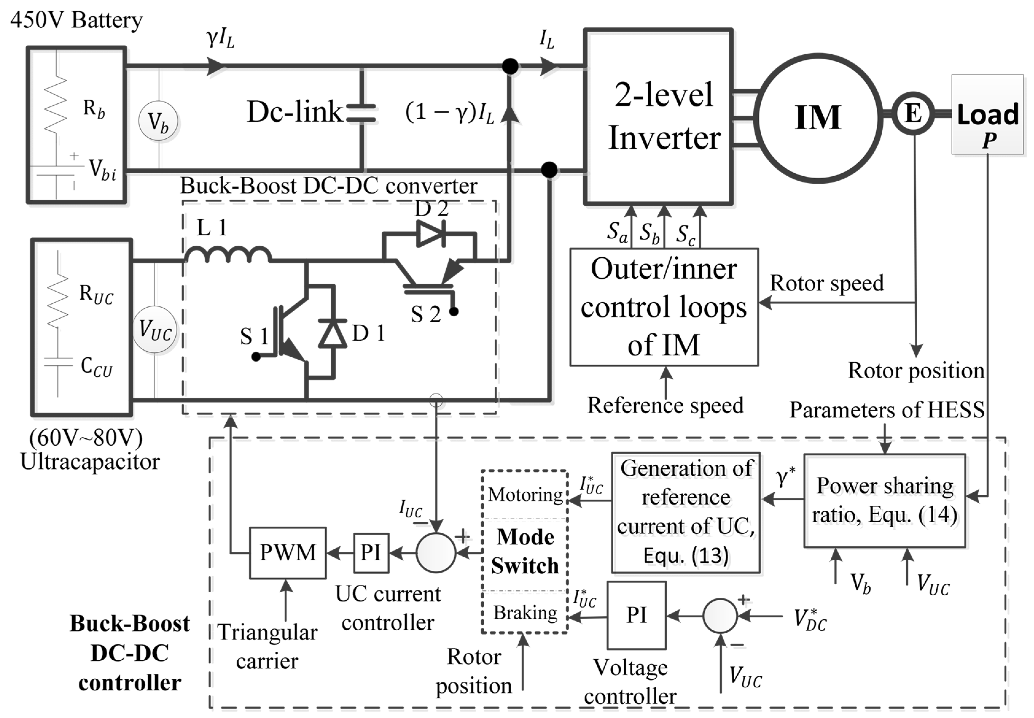
The adopted system consists of a three-phase induction motor, a two-level three-phase inverter, an ultracapacitor, a battery pack, and a DC link regulated by a DC-DC chopper, as illustrated in Figure 1. The IM operates in both motoring and generating modes; however, this paper focuses exclusively on the regenerative operation during braking periods. The DC-DC chopper functions in both buck and boost modes, depending on the vehicle’s driving cycle. The ultracapacitor and battery pack are connected to the DC bus through a buck–boost converter, which facilitates energy exchange with the load. The DC-DC converter, responsible for regulating current flow in the HESS, operates in two modes—buck and boost—depending on load conditions and the direction of power flow, as illustrated in Figure 1.
The operational modes discussed in this paper are as follows:
  • Mode 1: Charging the UC from the battery at light loads (Path E1): During this mode, the load is powered by the BP (Path E3), while the UC is charged. The chopper operates in buck mode, with switch S2 turned ON.
  • Mode 2: Charging the UC from the load during regenerative braking (Path E2): In this mode, the chopper remains in buck mode, with switch S2 ON, to store recovered energy in the UC.
  • Mode 3: Simultaneous charging of the UC from both the BP and the load (Paths E1 and E2). In Mode 3, the ultracapacitor is charged simultaneously from the regenerative braking system and the battery pack. This mode is enabled only when the energy recovered from braking is insufficient to meet the UC charging demand. A dedicated DC-DC converter allows supplementary power from the battery under controlled conditions. The energy management system monitors braking intensity, battery state-of-charge, and UC voltage to ensure safe operation, prevent overcharging, and optimize power flow efficiency.
  • Mode 4: Power sharing at heavy loads: The load current is drawn from both the battery (Path E3) and the UC (Path E4) through diode D2, following a load power sharing strategy, which will be explained in the next section.
In this system, the internal resistance of the BP is higher than that of UC. Therefore power loss of the BP path is higher. Therefore, with no load or/and light loads, the UC is charged by low current from the battery. At high load, the load current is drawn from both the BP and UC using the gamma distribution technique.

3. Control Strategy for Hybrid Energy Storage System

The battery pack is integrated with the ultracapacitor via a DC-DC chopper, enabling efficient energy exchange between the two storage components. The control methods of the chopper are illustrated in Figure 2. The chopper’s control signals are generated based on two primary modes of operation, buck mode and boost mode, which are selected according to the system’s operational requirements and load conditions. In buck mode, voltage control is applied to regulate the charging process of the UC, ensuring stable energy transfer. In contrast, boost mode employs current control to efficiently discharge energy from the UC to support the load. As shown in Figure 2, the appropriate control mode is selected by a mode switch based on the rotor position and its directional movement, optimizing energy utilization.
The system operates in two distinct modes:
Motoring Operation—The system functions in boost mode, utilizing current control to manage energy discharge from the UC, supplementing the battery to power the load efficiently.
Braking Operation—The system operates in buck mode, using voltage control to regulate energy recovery during regenerative braking, prioritizing UC charging to enhance system efficiency and prolong battery lifespan.

3.1. Motoring Operation (Boost Mode, Current Control, Discharge Mode)

During vehicle acceleration or cruising, the drive system operates in motoring mode. In this state, the ultracapacitor voltage is boosted to match the threshold DC link voltage, and both the UC and battery pack discharge to supply power to the load (mode 4). As shown in Figure 2, when the load power demand and UC parameters are known, the optimal power distribution ratio can be determined. Based on this ratio, the reference current for the UC is estimated. The reference current is then directly compared with the measured UC current using a proportional–integral (PI) controller, which generates the duty cycle for the UC’s unidirectional DC-DC converter.
The control signals for the DC-DC converter are generated through a pulse-width modulation (PWM) modulator. The boost mode of the DC-DC converter (i.e., discharging mode) is activated under high-load conditions, where the load current is supplied by both the BP and UC according to a predefined distribution factor, γ . To maximize discharge efficiency, the optimal distribution factor is first derived. Given that the output power of the induction motor is defined as P , the distribution factor is constrained within the range 0 γ 1 .
For a gamma distribution factor γ and consumed load power P , the power that is supplied from the battery to the load (E3 in Figure 1) is estimated as follows:
P b = γ P η i   η m = V b I b = V b R b I b I b ,
where V b is the no-load battery voltage, R b is the internal resistance of the BP, I b is the load current drawn from the BP, and η i and η m are efficiencies of the inverter and motor. The current of the battery is positive for discharge and negative for charging. For a given output–input power of the BP, the current and terminal voltage are easily determined by solving quadratic equation of (1).
For charging, the solution is as follows:
I b = V b V b 2 4 R b γ ( P η i   η m ) 2 R b
For discharge, the solution is as follows:
I b = V b V b 2 4 R b γ   ( P η i   η m ) 2 R b  
where V b , I b , and R b are the no-load voltage of battery, battery current, internal resistance of the battery, respectively; and η i and η m are the efficiencies of the inverter and IM, respectively.
By the same way, the power exerted from UC to the load can be calculated as follows:
P u c = 1 γ   ( P η i   η m ) = V u c   I u c = η c h ( V u c R u c I u c ) I u c
Then, UC current is expressed as follows:
I u c = 1 2 R u c   η c h . η c h V u c η c h 2   V u c 2 4 R u c η c h 1 γ ( P η i   η m ) ,
where V u c , I u c , and R u c are open-circuit voltage, current, and an internal resistance of the UC, respectively; and η c h is the efficiency of DC-DC converter.
The overall efficiency of the system at discharge mode could be given as follows:
η = P P b + P u c = P V b I b + V u c   I u c
Optimal distribution factor γ * , at which the maximum discharge efficiency could be achieved, is determined when η γ = 0 . It yields the following:
γ * = 4 R u c η c h ( P η i   η m ) + G V b 2 η c h 2 V u c 2 4 R b G + R u c η c h ( P η i   η m )
where G = R u c 4 V u c 2 R b 4 V b 2 . After obtaining γ * using (7), the reference current of the UC is obtained using (5). Then, the actual current is compared to the reference value of the UC and the error is treated by a PI current controller to obtain the control signal of the chopper via a PWM technique. This work focuses on optimizing instantaneous power distribution between energy sources during motoring operation. The control scheme maximizes discharge efficiency using a real-time distribution factor and current control. Although power balancing is the primary goal, the control transitions implicitly reflect time-dependent energy flow. However, cumulative energy effects—such as SoC behavior over extended cycles—are not explicitly modeled. Future work will address this by integrating energy-based constraints and long-term SoC management strategies.

3.2. Braking Operation (Buck Mode, Voltage Control, Charging Operation)

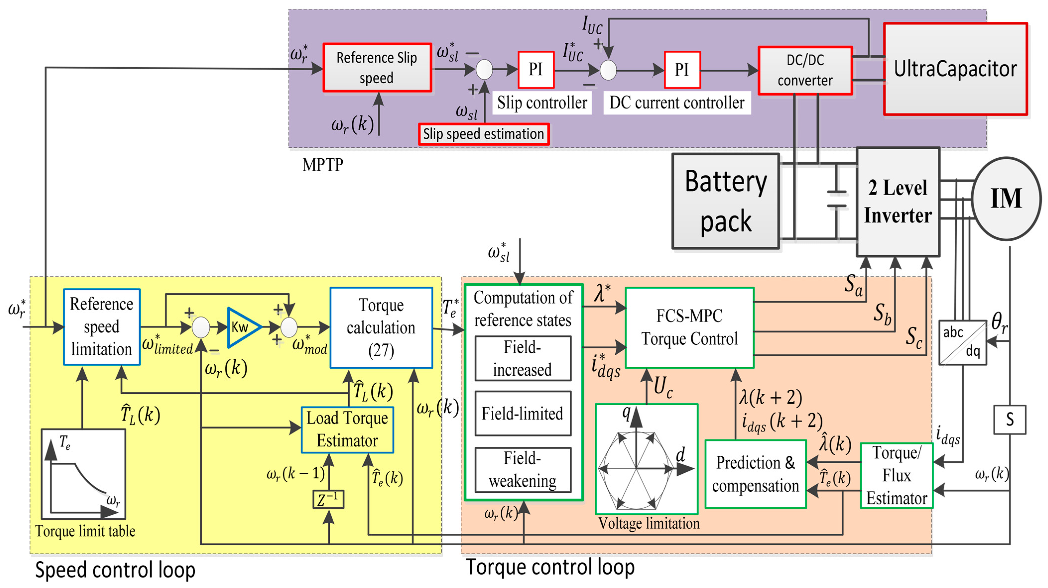
The buck mode is utilized for the regenerative braking operation of the IM. As shown in Figure 3, when the mode switch is set to braking mode the control system transitions accordingly. In this mode, a proportional–integral (PI) controller regulates the DC link voltage by generating the reference current for the UC. Once the reference current is determined, the same control sequence as in the previous mode is followed, including the generation of control signals via the modulator. Maximum power transfer point methodology is used to determine the optimal reference current of the UC at braking time (i.e., ω r * < ω r ). This subsection describes the dynamic behavior of the regenerative braking system. A slip speed control technique is employed to adjust the synchronous speed, enabling the IM to operate as a generator during braking.
The speed control strategy consists of two cascaded control loops:
  • Inner loop: Designed for torque control, implemented using a finite control set model predictive control (FCS-MPC) approach with an optimal duration technique, as previously adopted in [19,20].
  • Outer loop: Responsible for speed control, relying on an individual MPC cost function.
The speed and torque control loops are illustrated in Figure 3. In the following section, an MPC-based method is applied to control the IM during braking events.

Generation of Reference Torque T e * for IM

The dynamic relationship linking the inner and outer control loops is expressed as follows:
ω ˙ =   1 J B ω r + p T e p T L
where p , J , and B , are pole pairs, inertia, and the friction coefficient, respectively. The state form in the time domain of the dynamic system is as follows:
ω r k + 1 = ( 1 B T s w J ) ω r k + p   T s w J T e k p   T s w J T L k
where ω r k is the electrical speed and T s w is the sampling time of the speed loop. Due to the discrete nature of digital control platforms, (9) is discretized by Euler approximation. The discrete mechanical state space can be described as follows:
x m k + 1 =   A m x m k + B m u m k + E m d m [ k ]
where x m k = ω r [ k ] is the state variable, u m k is the input control variable, and the disturbance term d m represents the load torque T L [ k ] , assumed to be constant during the speed sampling time. The matrices A m , B m , and E m are defined as follows:
A m   = 1 B   T s w J ,   B m   = p   T s w J ,   E m   = p   T s w J .
When the IM works as a motor, the reference torque T e * , in this paper, is generated by a separate MPC presented in [19,20] in terms of state error x m * x m , which refers to speed error as follows:
T e * =   J p   T s w 1 + K m s x m * x m k + 1 k +   B m   T s w J x m k + 1 | k + p   T s w J T ^ L [ k ]
The steady-state error in speed is compensated by an integrator with a gain of K m s . In this method, the load torque is estimated T ^ L using a Kalman filter [19]. The inner loop for current control is implemented at the sampling time of T s whereas the outer loop is performed at the sampling time of speed loop T s w . The time T s w is taken as five times T s .
When the IM is controlled to stop or to decrease, a regenerative braking technique is employed. In this case, the reference state x m * decreases, i.e., it becomes lower than the current state x m . Given that T ^ L k represents a passive load torque, while friction torque acts as an active load, the reference torque T e * during complete motor stop ( x m * = 0 ) is given by the following:
T e * =   J p   T s w 1 + K m s x m k + 1 k +   B m   T s w J x m k + 1 | k p   T s w J T ^ L [ k ]
The negative reference torque T e * < 0 from Equation (12) can also be directly generated through the braking pedal, which provides a negative torque signal to initiate regenerative braking.

Reference Slip Speed ω s l *

In general, with the FOC of IM, the slip speed can be obtained as ω s l = 1 τ r i q s i d s . At braking ( ω r * < ω r ), the reference slip speed ω s l * = ( ω e * ω r ) becomes negative. Maximum torque per ampere control could be achieved when i d s * = i q s * . In this case, the slip speed is set to ω s l * = 1 / τ r , where τ r is the rotor time constant (=   R r / L r ). This means that the synchronous speed is controlled to be below the rotor speed when the IM is braked. Thus, the supply frequency is decreased in such a manner so as to operate the IM in the generating region to achieve regeneration.

Reference Rotor Flux λ *

As a result of decreasing the rotor speed, from the principle of the FOC of IM, the reference rotor flux linkage λ * can be determined by the following:
λ * = 2 3 2 P L r / τ r   T e * ω s l * = k λ   T e * ω s l * ,
where k λ = 2 3 2 P L r / τ r . The rotor flux linkage becomes a positive value because both T e * and ω s l * have same sign.

Reference Current Components i d q s *

The reference stator current components could be calculated in terms of reference flux and torque as follows:
i d s * = 1 L m λ * ,   i q s * = 2 3 2 P L r L m 1 λ * k T e *
The reference torque of (12) is carried out in the outer loop whereas the slip speed ω s l * , reference rotor flux λ * (13), and the reference stator current components i d q s * (14) are implemented in the inner loop. When the slip speed increases, the IM works as a generator to increase the voltage of the DC link above the normal value. The normal value of the DC link voltage is 450 Vdc, which represents the rated operating level during steady motoring. Values above this threshold indicate regenerative operation or overvoltage conditions that trigger appropriate control responses. Then, referring to Figure 3, the voltage error into the PI voltage controller becomes negative. This results in reversing the direction of the UC current, i.e., from discharging into charging mode.

4. Results and Analysis

4.1. Integration of Battery–Ultracapacitor HESS

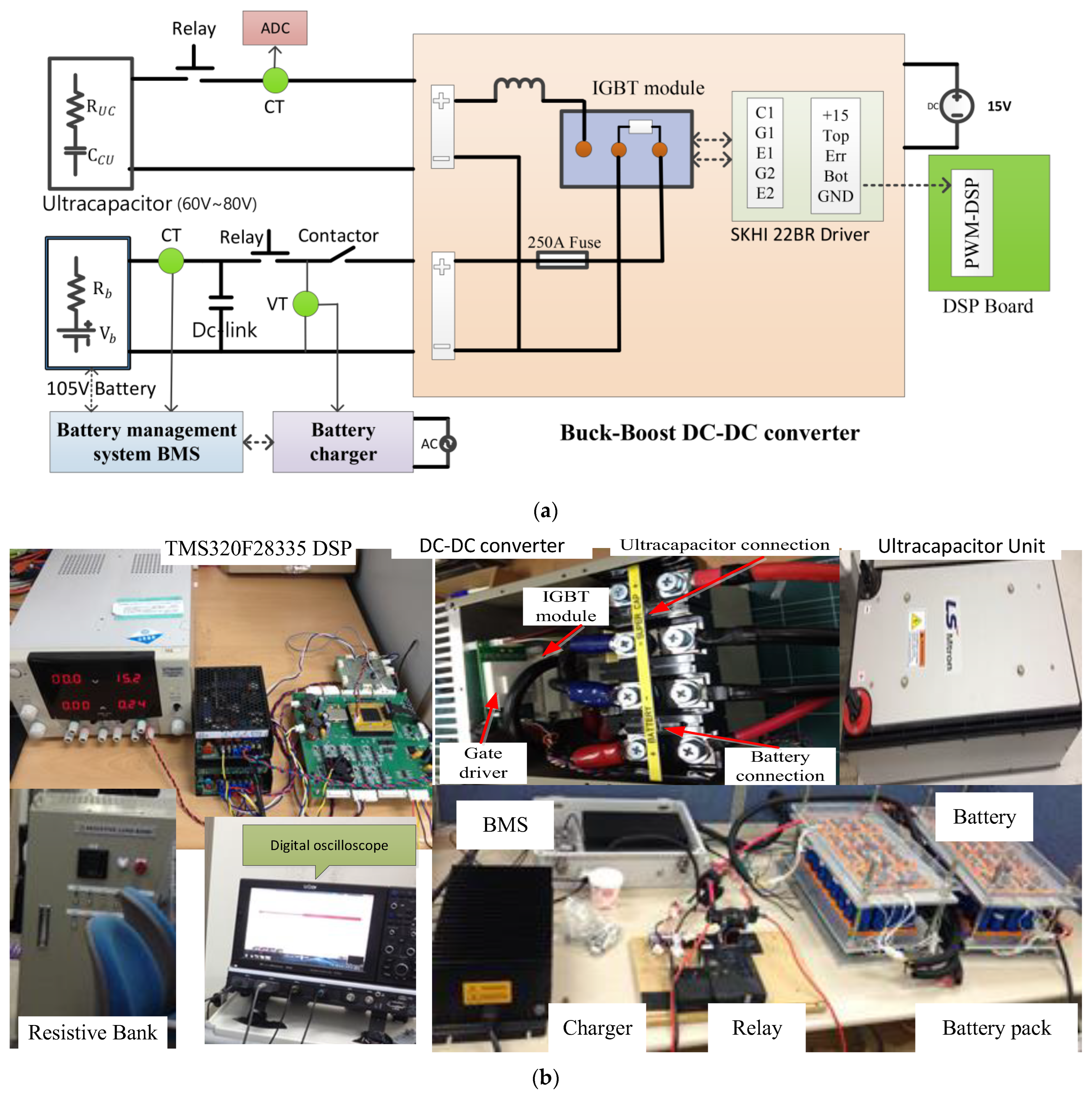
This section presents a preliminary stage in the development and control of the UC/battery HESS before integrating the UC in parallel with the battery within an electric vehicle. At this stage, the UC is connected in parallel with the battery via a buck–boost DC-DC converter to regulate power flow. The control strategy is designed to maximize energy transfer efficiency and is first validated through laboratory implementation with a static load. An experimental test bench was established to validate the proposed strategy outlined in Section 5. The schematic diagram of the test setup and photos of all of the equipment are illustrated in Figure 4. It consists of a lithium BP with its BMS and automatic charger, a specified UC module, a buck–boost DC-DC converter, and a static resistive load bank.
In the experimental setup, the UC, serving as an auxiliary energy storage unit, is integrated into the inverter’s DC link through a DC-DC converter. The ultracapacitor model “LS Mtron LSUM 086R4C 0093F EA” [21] is employed to support energy sharing with the load. The UC module is tested under both charging and discharging conditions, ensuring optimal power distribution. The detailed specifications of the UC module are listed in Table 1. The UC and lithium BP are coupled to the DC bus via a buck–boost converter, facilitating bidirectional energy exchange between the UC, BP, and load to enhance system performance.

4.2. Relationship Between Distribution Factor, Efficiency, and Load Power

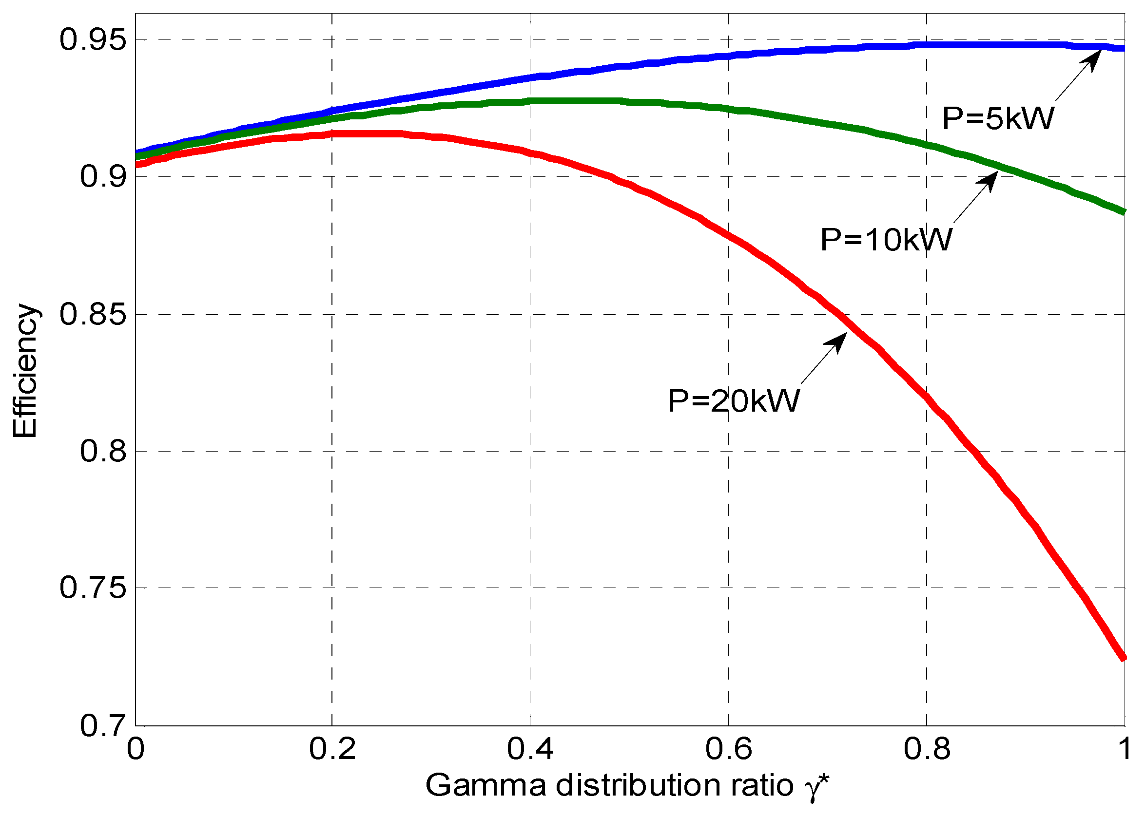
This section analyzes the relationship between overall discharge efficiency, the gamma distribution factor (γ), and load power (P). As derived in (7), the optimal duty that maximizes efficiency is dependent on the load power. Simulation results, illustrated in Figure 5, depict the variation of γ * at different power levels. The maximum efficiency is achieved at γ * = 0.85 , 0.45 ,   a n d   0.25 for load power values of 5 kW, 10 kW, and 20 kW, respectively. It is evident that γ * decreases as P increases. These findings suggest that, for higher loads, the ultracapacitor should play a more significant role in power distribution to optimize efficiency and enhance system performance.

4.3. Experimental Validation of Slip Control of IM for Regenerative Braking

In this stage, the proposed regenerative braking technique for the induction motor is experimentally validated. The experimental setup consists of a three-phase IM, a three-phase voltage source inverter, and an associated control system implemented on a TMS320F28335 Digital Signal Processor (DSP). The regenerative braking control strategy is executed using a slip speed control technique based on finite control set model predictive control. This approach enables precise control of the IM during braking, ensuring optimal energy recovery and system efficiency. Experimental tests were conducted to validate the slip control strategy of the IM and to quantify the amount of energy recovered during braking. The IM parameters used in the experiments are listed in Table 2.
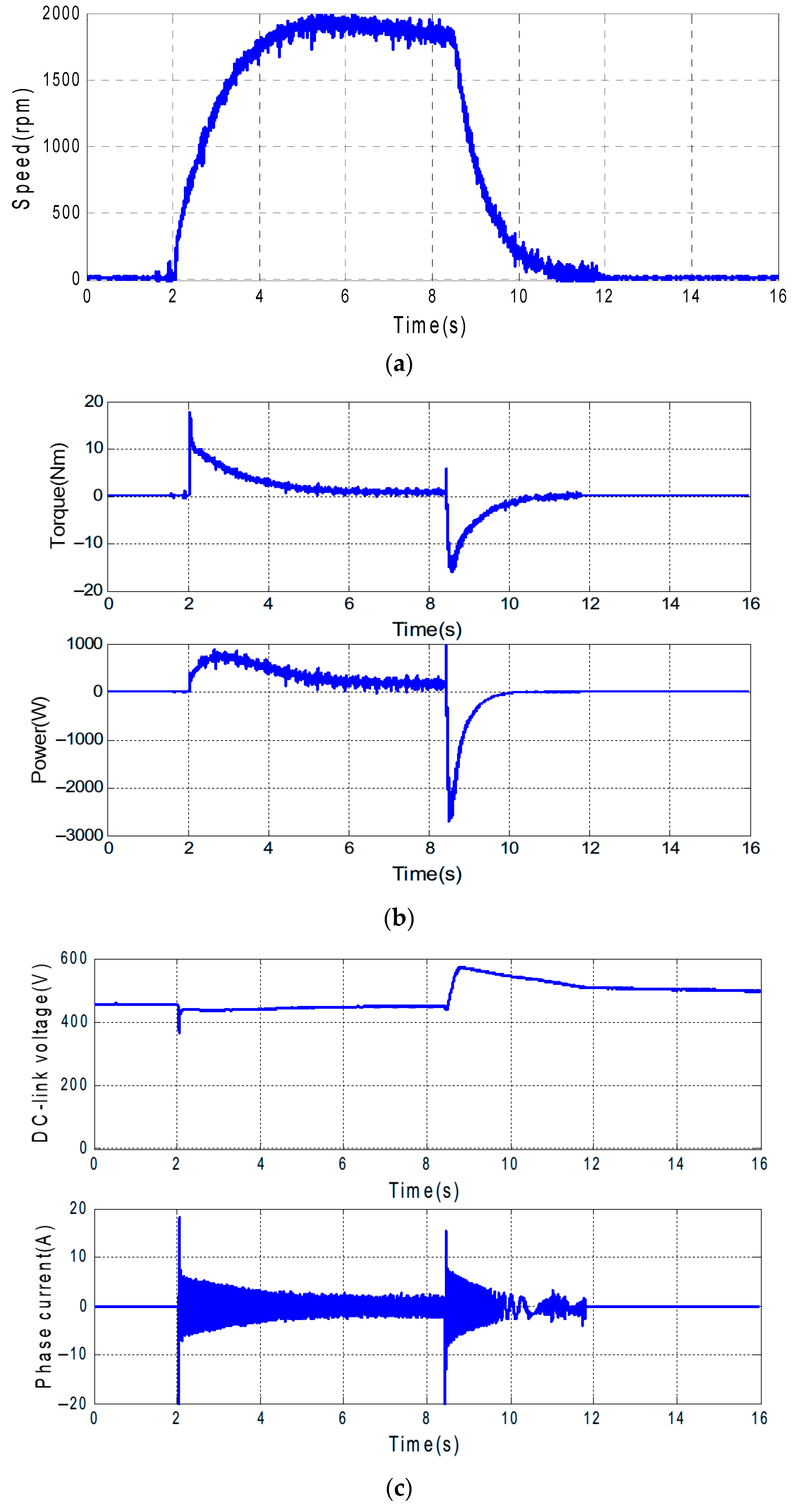
Initially, the motor operates at no load and runs at its rated speed of 1740 rpm to assess the effectiveness of the braking control. At time t = 0, the speed reference is set to zero, as depicted in Figure 6. During this transition, the motor speed decreases rapidly, while the phase-current increases, generating a reverse magnetomotive force that enables operation in generation mode. As a result, the developed torque becomes negative, leading to negative generated power. Additionally, the DC-bus voltage rises above 450 V, indicating surplus energy available for storage. This excess energy can be efficiently utilized to charge the ultracapacitor through the proposed control technique.
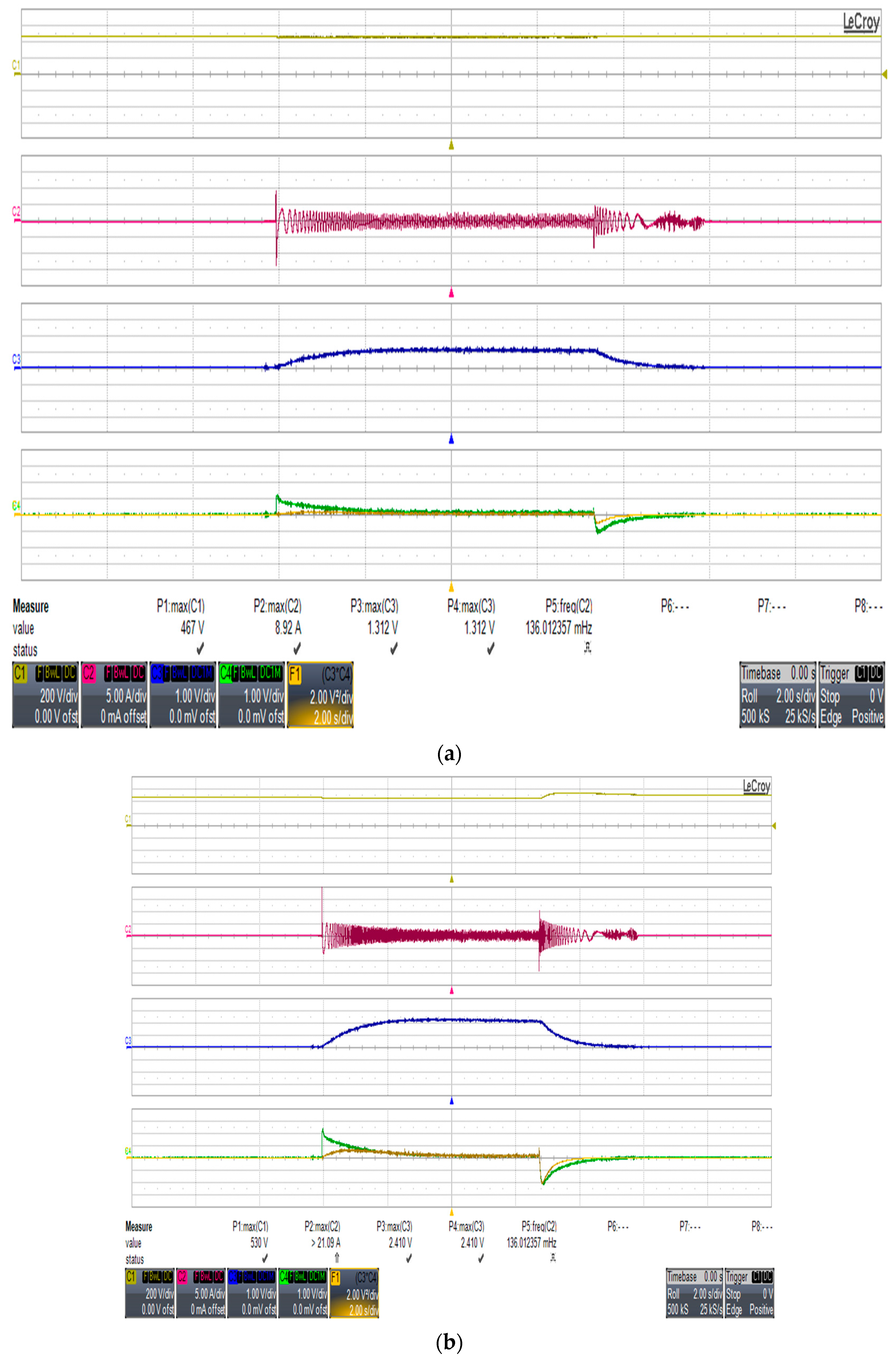
The experimental results in Figure 7 illustrate the performance of the IM operating in motoring mode at speeds of 600 rpm and 1200 rpm, respectively. After reaching a steady state, the IM transitions to the braking control mode. The results demonstrate the amount of energy that can be recovered and returned to the supply.
In this particular experiment a braking resistor is used to dissipate the regenerated energy. However, in the subsequent simulation results, we demonstrate how this recovered energy can be harnessed for fast charging the ultracapacitor instead of the battery pack, enhancing overall system efficiency.
The capacity of each component was determined based on a combination of laboratory testing, manufacturer specifications, and practical performance requirements related to the electric motor and drive system. The detailed process is as follows:
1.
Induction Motor (IM):
The capacity of the induction motor was selected based on its compatibility with experimental speed and torque control studies. The motor parameters are listed in Table 2.
2.
Battery Pack (BP):
The battery capacity was selected to ensure continuous operation of the motor under load and during regeneration.
The battery pack was assembled using a 32s4p LiFePO4 cell configuration, providing a total voltage of 100 V and a capacity of 40 Ah, as listed in Table 3. The system supports a maximum charge current of 18 A via the onboard charger.
This configuration was determined based on motor energy requirements, braking regeneration energy, and average power demands during acceleration and cruising, as evaluated in practical experiments.
3.
Ultracapacitor (UC) Module:
The UC was added to support the battery under high transient loads and regenerative braking. The sizing has been determined to provide fast charge/discharge capability while maintaining voltage stability at the DC link. The specifications of the selected UC have been listed in Table 4.
This module was selected to match the power demands of high dynamic events (e.g., quick acceleration or braking), based on simulation and experimental validations of the energy/power balance.
4.
DC Link Capacitor:
A 4700 μF capacitor was used at the DC link to buffer the voltage variations during power transitions between the motor, UC, and BP. This value was chosen based on typical practice and transient simulation results ensuring minimal voltage ripple at 450 Vdc.
5.
Power Electronics (DC-DC Converters):
Bidirectional buck–boost DC-DC converters were designed to interface the UC and BP with the 450 V DC link. The design specifications were based on the maximum power transfer expected during load/generation cycles.
In summary, the sizing process combined practical testing in the lab, matching load requirements of the IM, energy and power characteristics of the BP and UC, and ensuring voltage compatibility at the DC link. Where applicable, manufacturer datasheets and EV application best practices were also used.

4.4. Performance Assessment of HESS with a Static Load

Efficiency of Charge/Discharge in HESS

In the first experimental setup, the UC is connected in parallel with the BP via a DC/DC converter to supply a static load, as depicted in Figure 4. A 4 kW resistive load is used to evaluate the charge and discharge efficiency of the HESS. The energy flow efficiency is experimentally measured for both the battery and UC under different operating conditions. When the battery alone is used to power the load, the overall efficiency is observed to be 0.95 at low currents and 0.80 at very high currents. The efficiency reduction at high currents is attributed to internal resistance losses within the battery. With the integration of the UC, the efficiency of charging from the battery and discharging to the load is determined as 2 × (0.96 × 0.95) × 100 = 83%. This result demonstrates that at high current flow, the UC significantly enhances the energy transfer efficiency by mitigating the internal resistance effects of the battery.

Charging of Ultracapacitor from Battery (Path E1)

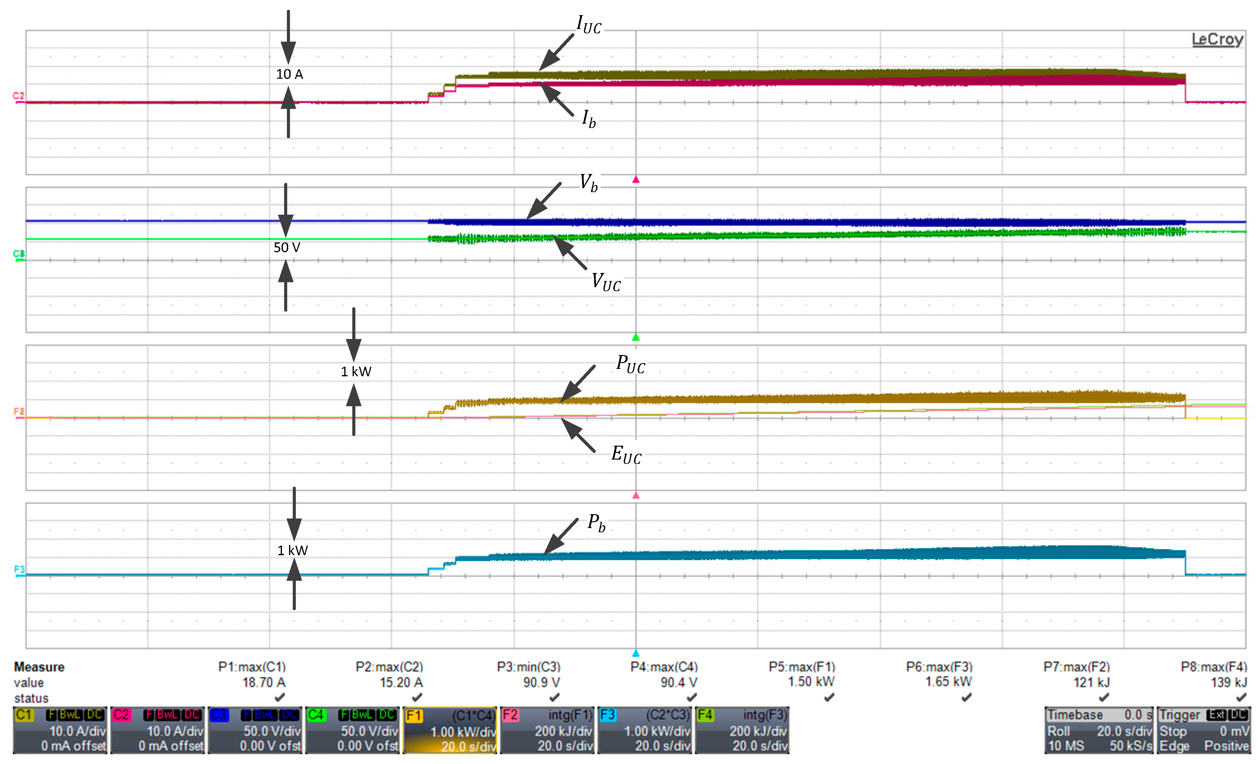
The experimental results for ultracapacitor charging from the battery pack are shown in Figure 8. In this operating mode, the BP supplies 10 A at 100 V, delivering 1 kW to charge the UC. Initially, the UC draws a high current, which gradually decreases to a steady-state current of 10 A, while the UC voltage increases progressively to 60 V. The total energy exported from the battery is measured as 139 kJ, while the energy stored in the UC through the DC-DC converter (path E1 in Figure 1) is found to be 121 kJ. The total energy extracted from the battery, including losses, is 142.359 kJ, with a battery power loss of 3.359 kJ. Thus, the efficiency of the DC-DC converter during UC charging is calculated as η c h = 121 139 = 0.87 . This result confirms that the DC-DC converter operates with an 87% efficiency during UC charging, highlighting its effectiveness in energy transfer.

Discharging of Battery to Load (Path 3)

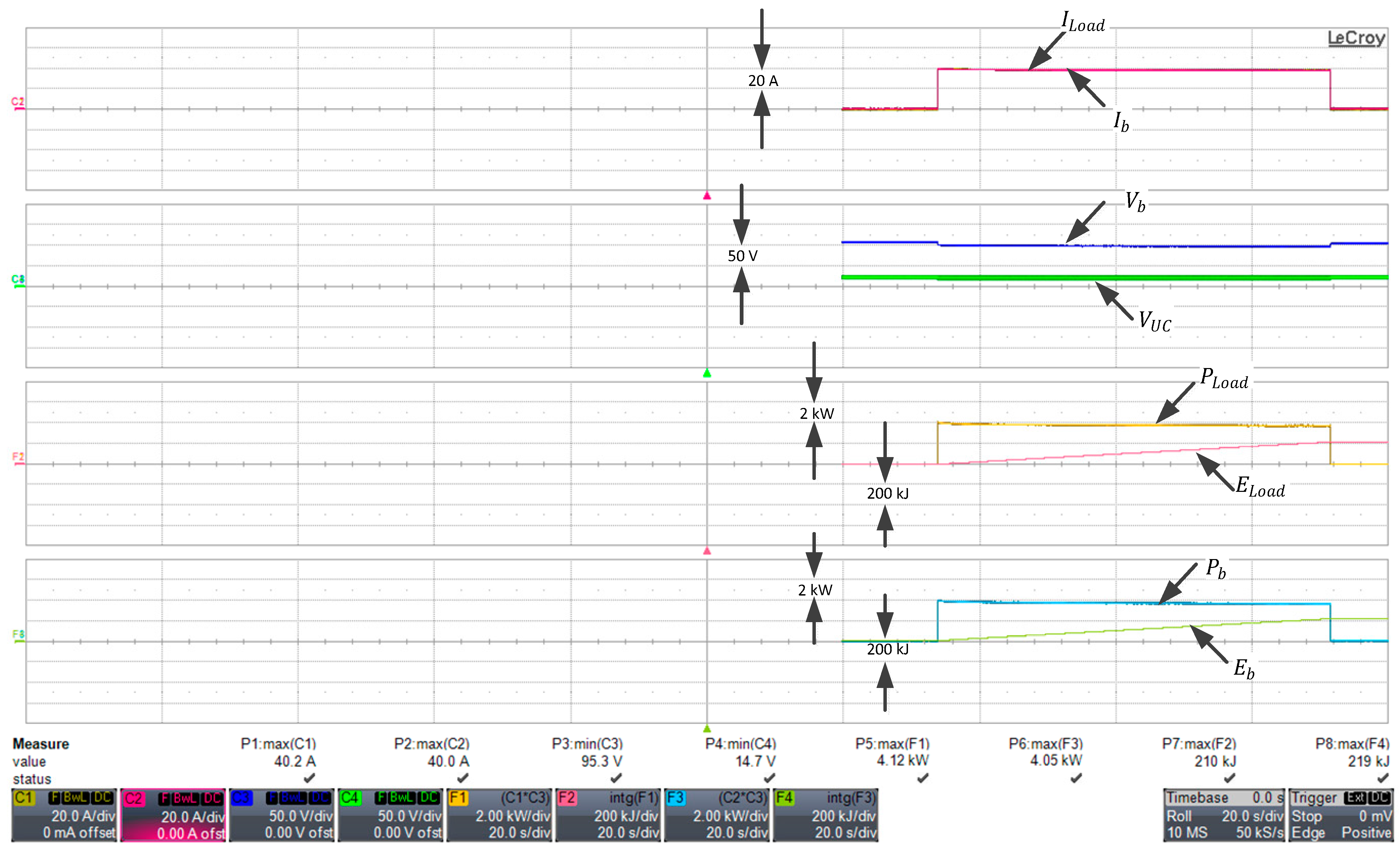
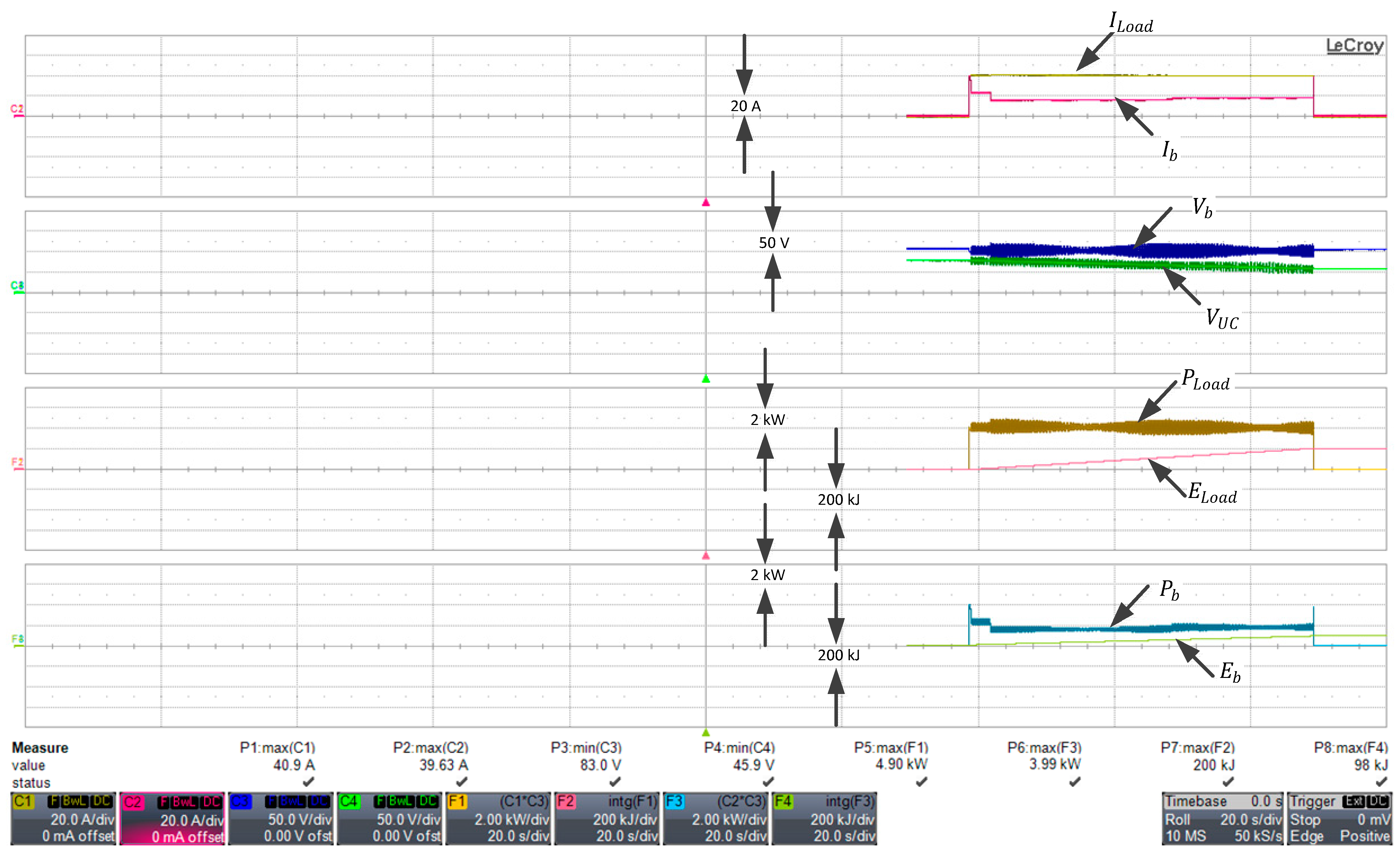
Figure 9 presents the experimental results when the battery supplies 40 A to the same static load. The battery voltage is 100 V, while the ultracapacitor voltage remains low at 20 V. Consequently, the 4 kW load power is entirely supplied by the battery. The power loss due to the battery’s internal resistance, as calculated by the BMS, is 17.55 kJ. The total energy supplied by the battery is 236.55 kJ, which matches the load energy over the same time period. The system efficiency is determined as η = 219000 / ( 219000 + 17550.83 ) × 100 = 92.58 % .

Discharging of BP and UC to Load (Path 3 + Path 4)

Figure 10 presents the experimental results when both the battery and the ultracapacitor supply power to the load. The total load current of 40 A is shared equally, with 20 A drawn from the battery and 20 A from the UC at a DC link voltage of approximately 100 V. Meanwhile, the UC supplies 33.33 A at 65 V at its terminals. The total discharge of energy delivered to the load is 200 kJ. The power loss due to the battery’s internal resistance is 3.256 kJ. The battery supplies 98 kJ of discharge energy to the load, while its total energy expenditure is 101.256 kJ. The UC receives 121 kJ of energy and delivers 102 kJ to the load. Considering that 142.359 kJ could be transferred from the battery to charge the UC, the total discharge efficiency is calculated as η = (200/(102 + 101.256)) × 100 = 98.5%. Compared to the case where the battery alone supplies the load, utilizing the UC improves discharge efficiency, thereby enhancing energy savings in frequent discharge operations.

4.5. Dynamic Performance with Regenerative Braking

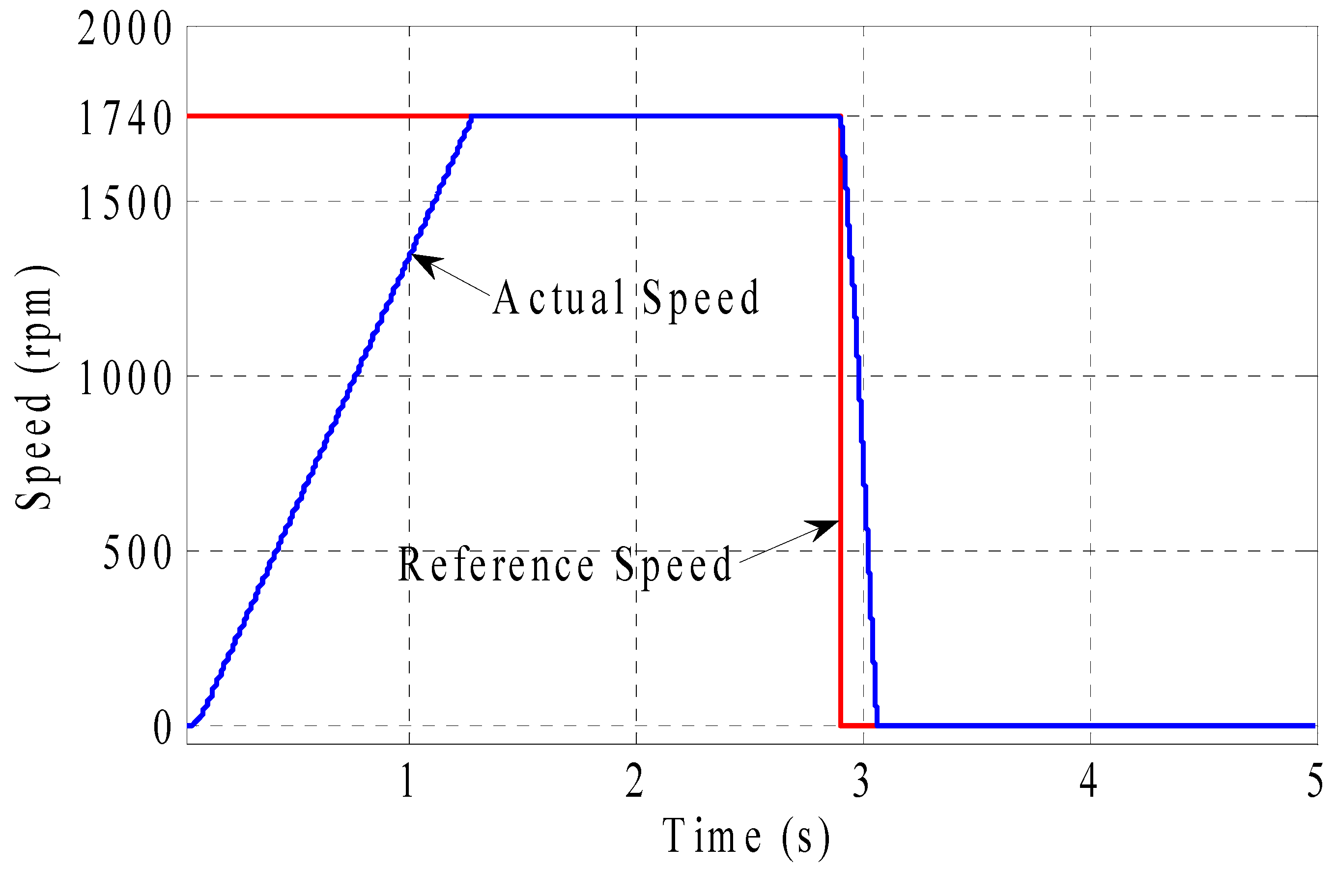
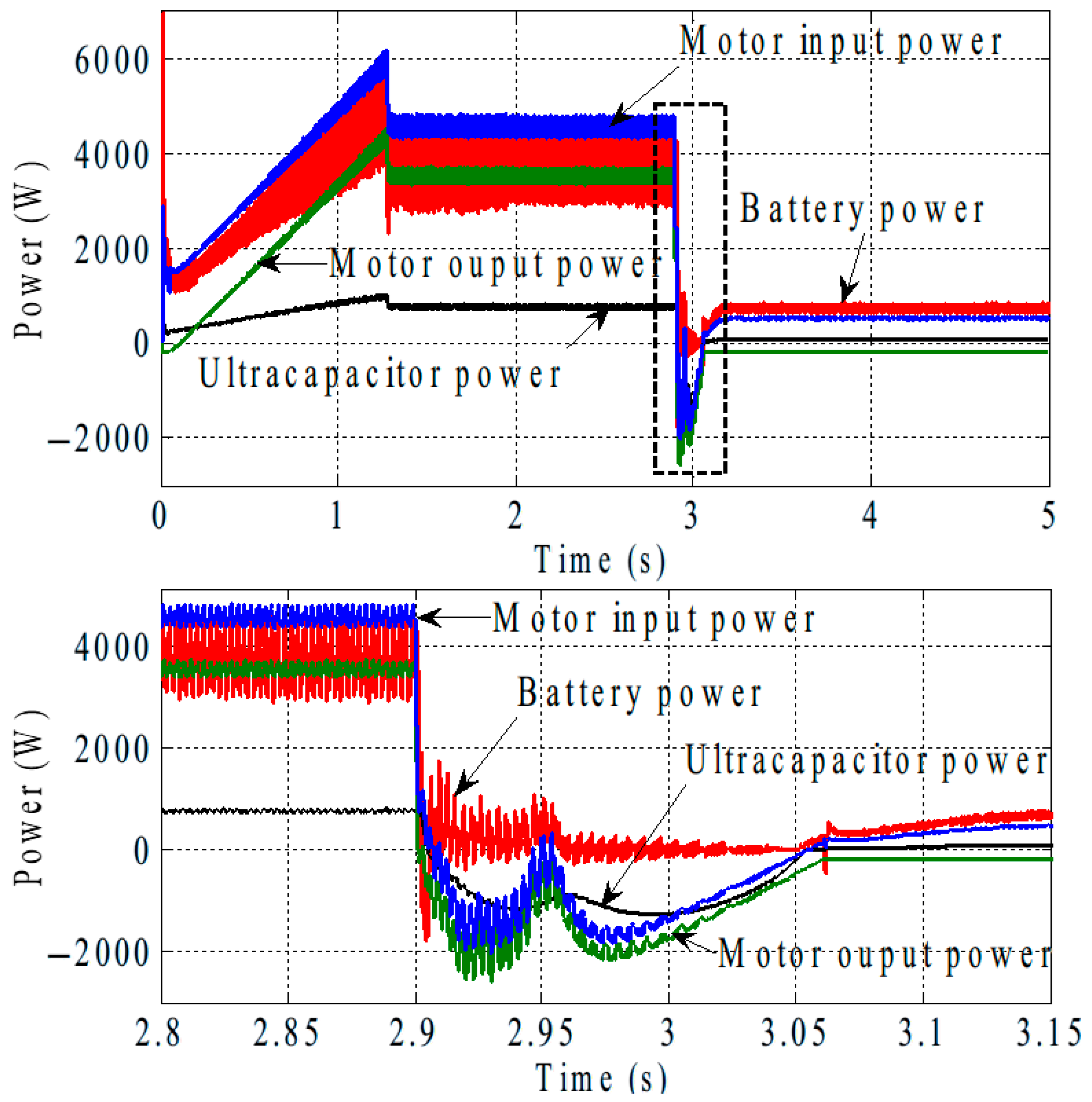
This subsection presents simulation results demonstrating the effectiveness of the proposed control schemes for the buck–boost chopper during both the regenerative braking and discharging modes of the adopted system. The results are obtained under rated load conditions of 20 Nm and a speed of 1740 rpm, as shown in Figure 11. Regenerative braking is initiated at t = 2.9 s, where the control strategy ensures that the motor speed closely follows the command speed during both acceleration and deceleration, exhibiting good dynamic performance.
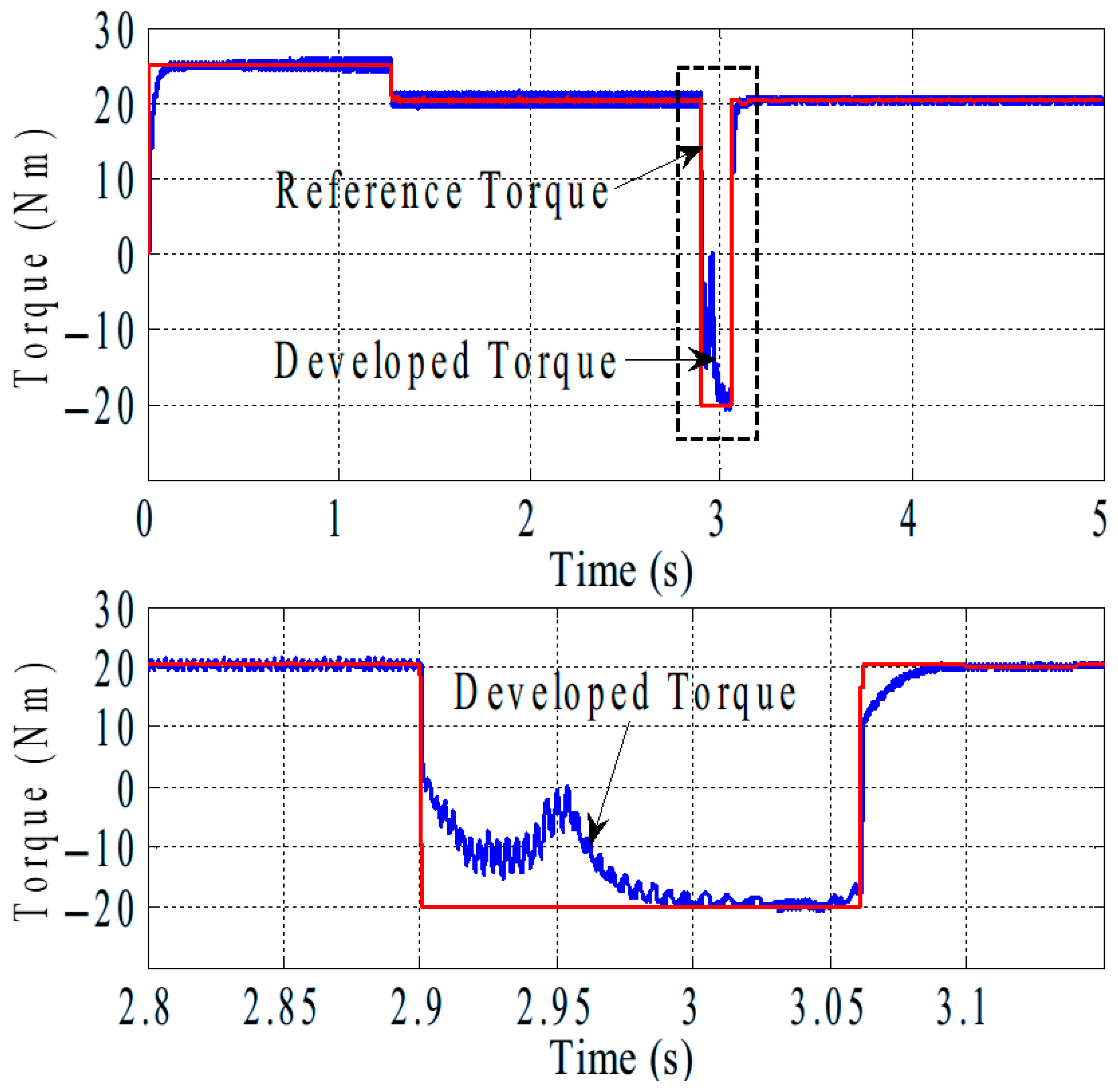
Corresponding to the speed response in Figure 11, the electromagnetic torque and its reference torque are illustrated in Figure 12. During acceleration, the torque is limited to 25 Nm, after which a full load of 20 Nm is maintained at the rated speed of 1740 rpm. When regenerative braking is applied, a negative torque of 20 Nm is developed. At t = 2.95 s, the torque exhibits an irregular shape due to the transition of the IM operating point from the flux-limited region to the flux-increased region [18,19].
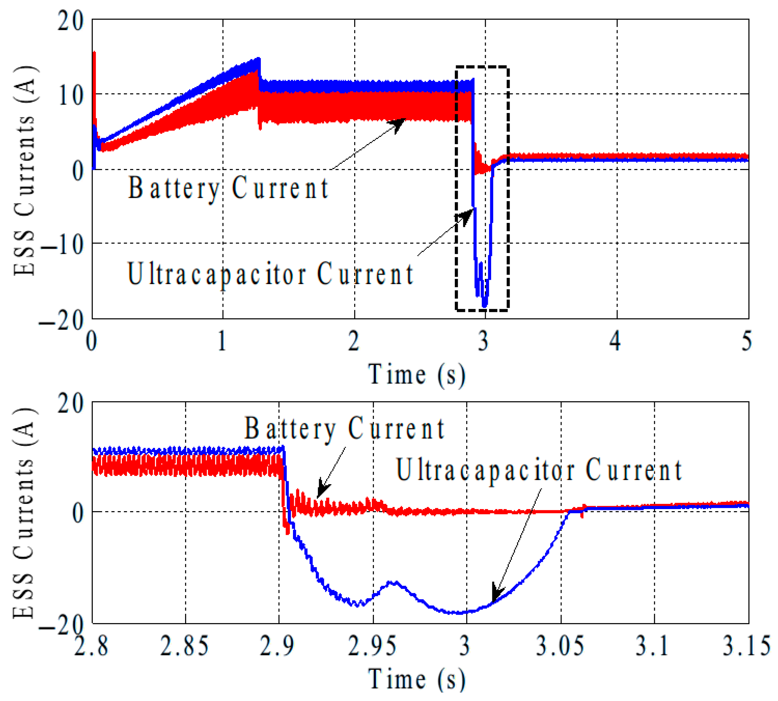
The corresponding BP and UC currents during both motoring (discharging) and braking (regenerative) modes are shown in Figure 13. During braking the reversed current flows entirely through the UC. In motoring mode the UC supplies 10 A at 70 V, while the battery provides 8 A at 450 V.
Figure 14 presents the input and output power of the IM, as well as the power contributions from the battery and UC. It is evident that the regenerated power is stored in the UC. At steady-state operation the UC delivers 0.8 kW, while the battery supplies 3.7 kW. The IM draws 4.5 kW from the inverter but delivers 3.7 kW to the load. During braking the battery is not charged, whereas the UC absorbs more than 1.0 kW of regenerative power.
Finally, Figure 15 illustrates the voltage profiles of the battery and UC. With the hybrid energy storage system (HESS), the battery and DC link voltages are effectively maintained at 450 V, while the UC voltage remains at 70 V.
To validate the energy storage feasibility of the proposed system, a complete round-trip efficiency analysis was conducted. The lithium-ion battery showed an average round-trip efficiency of approximately 92%, tested under a 1C rate and 25 °C ambient temperature. In contrast, the UC system combined with the bidirectional DC-DC converter exhibited a round-trip efficiency of about 74%, due to converter losses during both charging and discharging phases. These results support the control strategy, which leverages the battery for sustained energy supply and prioritizes the UC for fast transients.

5. Conclusions

This paper presented a successful control method for regulating the speed of an induction motor during both running and braking operations. Experimental results demonstrate that the proposed control strategy effectively enables the IM to regenerate power to its DC link bus during braking. This regenerated energy is efficiently utilized to charge the ultracapacitor, enhancing overall system efficiency. A control strategy for the coordinated discharging of both the UC and the battery was also introduced, showing that power flow efficiency can be improved by optimizing the distribution factor.
Preliminary experimental results confirm the successful integration of the UC with the battery in the laboratory, validating the proposed energy distribution method. The findings highlight that using a UC in parallel with the battery increases system efficiency, particularly in regenerative braking scenarios. Future research will focus on optimizing the efficiency of the hybrid UC/battery-powered hybrid energy storage system and integrating it into electric vehicles.
Key findings include the following:
  • The proposed control technique efficiently utilizes excess energy to charge the UC.
  • For higher load demands the UC plays a crucial role in power distribution, optimizing efficiency and system performance.
  • The DC-DC converter achieves 87% efficiency during UC charging, demonstrating effective energy transfer.
  • Compared to a battery-only configuration (82%), incorporating a UC improves discharge efficiency (92%) and enhances energy savings in frequent discharge operations.
In this paper, a supercapacitor (UC)-based energy storage system integrated with a bidirectional DC-DC converter has been designed, implemented, and evaluated. The system was developed to assess the charging and discharging behavior of the UC under various load conditions. The converter’s efficiency is measured during both charging and discharging phases and compared to the overall system performance with that of a conventional lithium-ion battery. Experimental results were used to analyze energy transfer efficiency, evaluate the converter’s dynamic response, and discuss the feasibility of using UCs in real-world energy applications. The complete energy efficiency analysis confirms that the lithium-ion battery subsystem is more efficient than the UC-based system in terms of energy storage. However, the UC still plays a critical role in handling dynamic load demands due to its fast response, justifying the hybrid configuration.

Author Contributions

Conceptualization, A.A.A., Y.I.L. and A.A.Z.D.; Methodology, A.A.A., Y.I.L., S.A.D. and A.A.Z.D.; Software, A.A.A., Y.I.L., A.A.Z.D. and A.A.E.; Validation, A.A.A., Y.I.L., S.A.D. and A.A.Z.D.; Formal analysis, A.A.Z.D. and A.A.E.; Investigation, A.A.A., Y.I.L., S.A.D. and A.A.Z.D.; Resources, A.A.A. and Y.I.L.; Data curation, A.A.A., Y.I.L., A.A.E. and S.A.D.; Writing—original draft preparation, A.A.A., Y.I.L. and A.A.Z.D.; Writing—review and editing, A.A.A., Y.I.L., S.A.D., A.A.Z.D. and A.A.E.; Visualization, A.A.A., Y.I.L., S.A.D. and A.A.Z.D.; Supervision, A.A.A. and Y.I.L.; Project administration, A.A.A.; Funding acquisition, A.A.A., Y.I.L. and S.A.D. All authors have read and agreed to the published version of the manuscript.

Funding

This research received no external funding.

Data Availability Statement

The original contributions and data presented in this study are included in the article.

Conflicts of Interest

The authors declare no conflicts of interest.

References

  1. Eftekhari, A. Low voltage anode materials for lithium-ion batteries. Energy Storage Mater. 2017, 7, 157–180. [Google Scholar] [CrossRef]
  2. Burke, A.; Miller, M. The power capability of ultracapacitors and lithium batteries for electric and hybrid vehicle applications. J. Power Sources 2011, 196, 514–522. [Google Scholar] [CrossRef]
  3. Emadi, A.C. 8: Hybrid Energy Storage Systems. In Advanced Electric Drive Vehicles; Taylor & Francis Group, LLC: Boca Raton, FL, USA, 2015; pp. 285–286. [Google Scholar]
  4. Camara, M.B.; Gualous, H.; Gustin, F.; Berthon, A.; Dakyo, B. DC/DC converters design for supercapacitors and battery power management in hybrid vehicle applications-polynomial control strategy. IEEE Trans. Ind. Electron. 2010, 57, 587–597. [Google Scholar] [CrossRef]
  5. Bian, Y.; Zhu, L.; Lan, H.; Li, A.; Xu, X. Regenerative braking strategy for motor hoist by ultracapacitor. Chin. J. Mech. Eng. 2012, 25, 377–384. [Google Scholar] [CrossRef]
  6. Xiang, C.; Wang, Y.; Hu, S.; Wang, W. A New Topology and Control Strategy for a Hybrid Battery-Ultracapacitor Energy Storage System. Energies 2014, 7, 2874–2896. [Google Scholar] [CrossRef]
  7. Awerbuch, J.J.; Sullivan, C.R. Control of Ultracapacitor-Battery Hybrid Power Source for Vehicular Applications. In Proceedings of the 2008 IEEE Energy 2030 Conference, Atlanta, GA, USA, 17–18 November 2008. [Google Scholar]
  8. Chau, K.T.; Wong, Y.S. Hybridization of energy sources in electric vehicles. Energy Convers. Manag. 2001, 42, 1059–1069. [Google Scholar] [CrossRef]
  9. Miller, J.R. Engineering electrochemical capacitor applications. J. Power Sources 2016, 326, 726–735. [Google Scholar] [CrossRef]
  10. Ehsani, M.; Gao, Y.; Emadi, A. Modern Electric, Hybrid Electric, and Fuel Cell Vehicles: Fundamentals, Theory, and Design, 2nd ed.; Power Electronics and Applications Series; CRC Press: Boca Raton, FL, USA, 2010. [Google Scholar]
  11. So, K.M.; Wong, Y.S.; Hong, G.S.; Lu, W.F. An improved energy management strategy for a Battery/Ultracapacitor Hybrid Energy Storage System in Electric Vehicles. In Proceedings of the 2016 IEEE Transportation Electrification Conference and Expo (ITEC), Dearborn, MI, USA, 27–29 June 2016; pp. 1–6. [Google Scholar]
  12. Ahmed, A.; Cui, S. Control and analysis of regenerative power distribution on electrical variable transmission using fuzzy logic on HEV system. In Proceedings of the International Conference on Electrical Machines and Systems (ICEMS), Beijing, China, 20–23 August 2011. [Google Scholar]
  13. Mahapatra, A.A.; Gopalakrishna, S. Regenerative braking in induction motor drives in applications to electric vehicles. In Proceedings of the 2014 IEEE Students’ Conference on Electrical, Electronics and Computer Science, Bhopal, India, 1–2 March 2014. [Google Scholar]
  14. Li, Z.; Pan, Y. On steering regenerative brake torque control of dual-motor drive for electric tracked vehicle. In Proceedings of the IEEE International Conference on Automation and Logistics, Beijing, China, 29–31 August 2010. [Google Scholar]
  15. Kouchachvili, L.; Yaïci, W.; Entchev, E. Hybrid battery/supercapacitor energy storage system for the electric vehicles. J. Power Sources 2018, 374, 237–248. [Google Scholar] [CrossRef]
  16. Chen, S.; Yang, Q.; Zhou, J.; Chen, X. Hybrid energy storage system control method based on model predictive control. CSEE J. Power Energy Syst. 2020, 7. [Google Scholar] [CrossRef]
  17. Punna, S.; Behera, P.; Lamba, A. A Power Management Scheme for Electric Vehicles with Hybrid Energy Storage Systems. In Proceedings of the 2024 IEEE 4th International Conference on Sustainable Energy and Future Electric Transportation (SEFET), Hyderabad, India, 31 July–3 August 2024; pp. 1–5. [Google Scholar]
  18. Ahmed, A.A.; Mousa, M.G.; Lee, Y.I. Regenerative braking control of IM with battery/ultracapacitor hybrid ESS in electric vehicles. In Proceedings of the 2017 Nineteenth International Middle East Power Systems Conference (MEPCON), Cairo, Egypt, 19–21 December 2017; pp. 320–325. [Google Scholar]
  19. Ahmed, A.A.; Koh, B.K.; Park, H.S.; Lee, K.-B.; Lee, Y.I. Finite control set model predictive control method for torque control of induction motors using a state tracking cost index. IEEE Trans. Ind. Electron. 2017, 64, 1916–1928. [Google Scholar] [CrossRef]
  20. Ahmed, A.A.; Koh, B.K.; Lee, Y.I. A Comparison of Finite Control Set and Continuous Control Set Model Predictive Control Schemes for Speed Control of Induction Motors. IEEE Trans. Ind. Inform 2017, 14, 1334–1346. [Google Scholar] [CrossRef]
  21. Orion BMS. Available online: http://www.orionbms.com/ (accessed on 22 July 2025).
  22. Boglou, V.; Karavas, C.-S.; Karlis, A.; Arvanitis, K.G.; Palaiologou, I. An optimal distributed RES sizing strategy in hybrid low voltage networks focused on EVs’ integration. IEEE Access 2023, 11, 16250–16270. [Google Scholar] [CrossRef]
  23. Karavas, C.-S.; Arvanitis, K.G.; Papadakis, G. Optimal technical and economic configuration of photovoltaic powered reverse osmosis desalination systems operating in autonomous mode. Desalination. 2019, 466, 97–106. [Google Scholar] [CrossRef]
  24. Boglou, V.; Karavas, C.; Karlis, A.; Arvanitis, K. An intelligent decentralized energy management strategy for the optimal electric vehicles’ charging in low-voltage islanded microgrids. Int. J. Energy Res. 2022, 46, 2988–3016. [Google Scholar] [CrossRef]
  25. Rimpas, D.; Kaminaris, S.D.; Piromalis, D.D.; Vokas, G.; Arvanitis, K.G.; Karavas, C.-S. Comparative review of motor technologies for electric vehicles powered by a hybrid energy storage system based on multi-criteria analysis. Energies 2023, 16, 2555. [Google Scholar] [CrossRef]
  26. Loukatos, D.; Arapostathis, V.; Karavas, C.-S.; Arvanitis, K.G.; Papadakis, G. Power consumption analysis of a prototype lightweight autonomous electric cargo robot in agricultural field operation scenarios. Energies 2024, 17, 1244. [Google Scholar] [CrossRef]
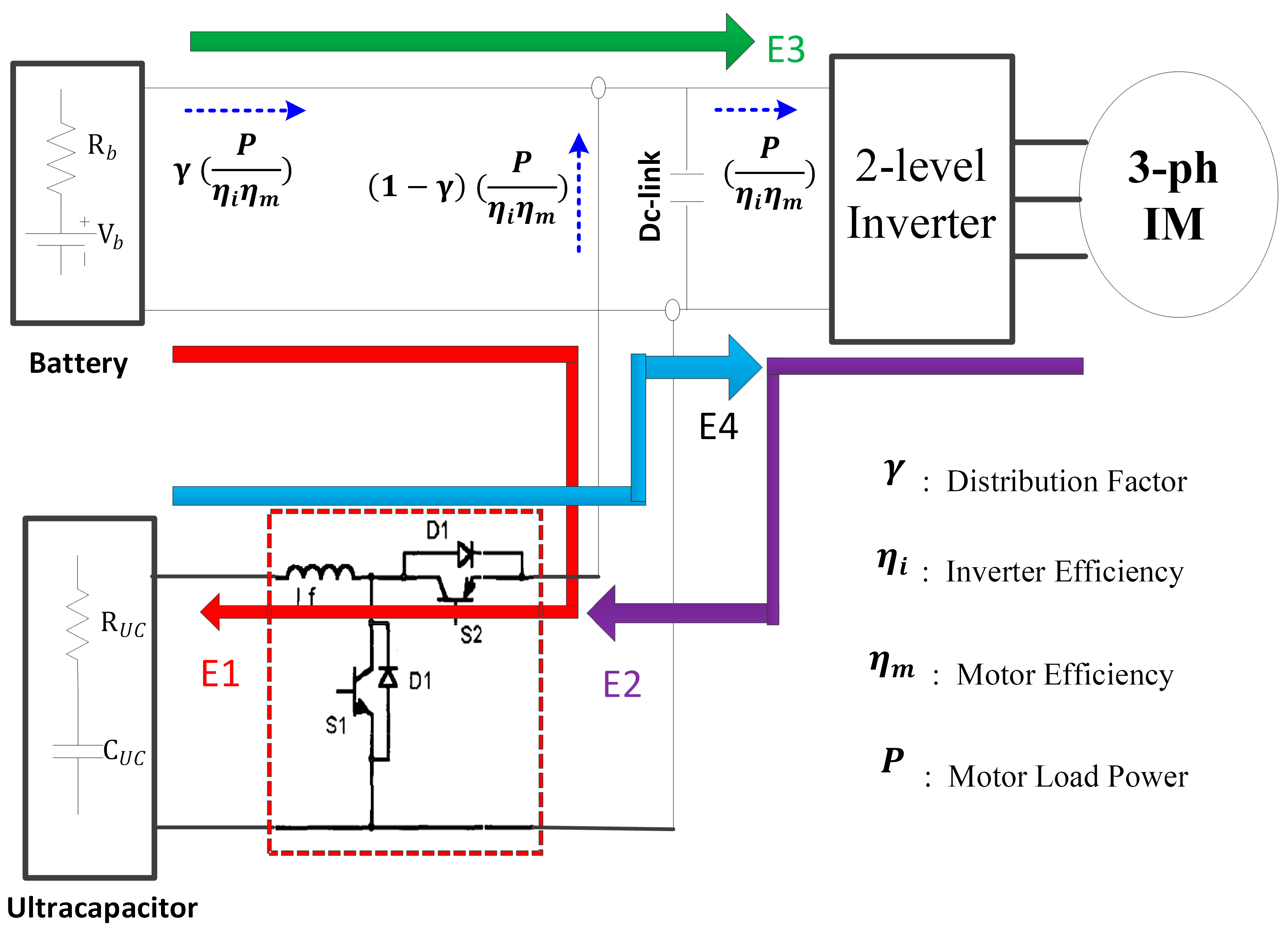
Figure 1. Integration of BP and UC by DC-DC converter for IM drive.
Mca 30 00082 g001
Figure 2. Battery/ultracapacitor with control principle of buck–boost control.
Mca 30 00082 g002
Figure 3. Control system of IM in motoring and braking modes. The lower part was implemented by the first author in [11,12].
Mca 30 00082 g003
Figure 4. Experiment set of battery/ultracapacitor charge/discharge tests: (a) schematic diagram, and (b) photo of setup.
Mca 30 00082 g004
Figure 5. Discharge efficiency and gamma distribution factor.
Mca 30 00082 g005
Figure 6. Experimental results (plotted in Matlab) of braking test of IM when it runs at 1740 rpm: (a) motor speed, (b) developed torque and motor power, (c) DC voltage and phase current.
Mca 30 00082 g006
Figure 7. Experimental results at braking test of IM from top to bottom: DC link voltage, phase current, motor speed, developed torque, and motor power when machine runs at: (a) 600 rpm and (b) 1200 rpm.
Mca 30 00082 g007
Figure 8. Experimental results when UC is charged from battery, from top to bottom: UC and battery currents [10 A/div], battery and UC voltages [50 V/div], UC power [1 kW/div] and energy, and battery power [1 kW/div].
Mca 30 00082 g008
Figure 9. Experimental results when static load is supplied from battery only, from top to bottom: load and battery currents [20 A/div], battery and UC voltages [50 V/div], load power [2 kW/div] and energy [200 kJ/div], and battery power [2 kW/div] and energy [200 kJ/div].
Mca 30 00082 g009
Figure 10. Experimental results when UC and battery are discharged to static load, from top to bottom: load and battery currents [20 A/div], battery and UC voltages [50 V/div], load power [2 kW/div] and energy [200 kJ/div], and battery power [2 kW/div] and energy [200 kJ/div].
Mca 30 00082 g010
Figure 11. Speed response of IM.
Mca 30 00082 g011
Figure 12. Electromagnetic torque of the adopted IM.
Mca 30 00082 g012
Figure 13. Battery and ultracapacitor currents.
Mca 30 00082 g013
Figure 14. Power of battery, IM, and ultracapacitor.
Mca 30 00082 g014
Figure 15. Battery and ultracapacitor voltage.
Mca 30 00082 g015
Table 1. Specifications of LS Mtron LSUM 086R4C 0093F EA.
Specification [unit]ValueSpecification [unit]Value
Rated voltage [V]86.4Maximum current [A]80
Capacitance [F]93Max. stored energy [Wh/kg]3.7
Resistance [ m Ω ] 11.3Weight [kg]26
Table 2. Induction motor parameters.
Quantity Symbol Value
DC-bus volt [ V ] V d c 450
Number of Poles P 4
Rated voltage [V] Y / 220/380
Rated current [A] 14.2/8.2
Stator Resistance [ Ω ] R s 1.77
Rotor Resistance [ Ω ] R r 1.275
Stator Inductance [ H ] L s 0.157
Rotor Inductance [ H ] L r 0.158
Mutual Inductance [ H ] L m 0.15
Inertia coefficient [Kg·m2]J0.00006
Rated Motor Speed [ r p m ] ω N 1740
Rated Power [ k W ] P N 3.7
Table 3. Battery pack configuration and specifications for the LiFePO4-based HESS used in the proposed EV system.
ParameterSpecification
Configuration32s4p LiFePO4 cells
Cell Voltage/Capacity3.2 V/10 Ah
Total Pack Voltage100 V
Total Pack Capacity40 Ah
Total Energy4.0 kWh
Max Charge Current18 A (via onboard charger)
Table 4. Specifications of the selected UC module used for transient load support and regenerative braking in the HESS.
ParameterSpecification
ModelLS Mtron LSUM 086R4C 0093F EA
Rated Voltage86.4 V
Capacitance93 F
Maximum Current80 A
Internal Resistance11.3 mΩ
Disclaimer/Publisher’s Note: The statements, opinions and data contained in all publications are solely those of the individual author(s) and contributor(s) and not of MDPI and/or the editor(s). MDPI and/or the editor(s) disclaim responsibility for any injury to people or property resulting from any ideas, methods, instructions or products referred to in the content.