Article

Evaluation of Aortic Valve Pressure Gradients for Increasing Severities of Rheumatic and Calcific Stenosis Using Empirical and Numerical Approaches

1
Institute of Biomedical Engineering, Department of Mechanical and Mechatronic Engineering, Stellenbosch University, Stellenbosch 7600, South Africa
2
Division of Cardiology, Faculty of Medicine and Health Sciences, Stellenbosch University, Cape Town 7505, South Africa
*
Author to whom correspondence should be addressed.
Math. Comput. Appl. 2024, 29(3), 33; https://doi.org/10.3390/mca29030033
Submission received: 12 March 2024 / Revised: 18 April 2024 / Accepted: 24 April 2024 / Published: 28 April 2024

Abstract

:
The evaluation and accurate diagnosis of the type and severity of aortic stenosis relies on the precision of medical imaging technology and clinical correlations and the expertise of medical professionals. The application of the clinical correlation to different aortic stenosis morphologies and severities is investigated. The manner in which numerical techniques can be used to simulate the blood flow through pathological aortic valves was analysed and compared to the ground-truth CFD model. Larger pressure gradients are estimated in all severities of rheumatic aortic valves compared to calcific aortic valves. The zero-dimensional morphology-insensitive model underpredicted the transvalvular pressure gradient with the greatest error. The 1D model underestimated the pressure gradient in rheumatic cases and overestimated the pressure gradient in calcific cases. The pressure gradients estimated by the clinical approach depends on the location of the flow vena contracta and is sensitive to the severity and type of valve lesion. Through the analysis of entropy generation within the flow domain, the dominant parameters and regions driving adverse pressure gradients were identified. It is concluded that sudden expansion is the dominant parameter leading to higher pressure gradients in rheumatic heart valves compared to calcific ones.

1. Introduction

The aortic valve is situated in a complex haemodynamic environment between the left ventricle (LV) and the aorta, the largest artery in the human body. The aortic valve rapidly opens during systole and closes during diastole approximately 100,000 times per day to regulate blood flow and pressure throughout the body, an essential element to sustain human life [1]. Valvular heart disease (VHD) describes the pathological condition where heart valves are affected by abnormalities caused by congenital malformation, degeneration, or infection [2]. The three most common types of VHD are aortic stenosis, mitral regurgitation, and mitral stenosis. Aortic stenosis (AS) is the valve pathology described by the narrowing of the valve opening area. It is the VHD where physical medical intervention is most often required in Europe and North America [1,3]. The prevalence of VHD increases with age where degenerative VHDs are more prevalent in industrial countries and rheumatic heart disease leading in developing countries. The diagnoses and management protocol of patients with VHD are described in both the European Society of Cardiology (ESC)/European Association for Cardio-Thoracic Surgery (EACTS) and the American College of Cardiology (ACC)/American Heart Association (AHA) guidelines on the management of patients with VHD [3,4]. The left ventricle’s mechanical work demand is related to the dissipated lost work across the aortic heart valve, given the non-linear relationship between cardiac output and pressure gradient. Hence, accurately estimating the pressure gradient across the aortic valve is vital for diagnosing AS.
Diagnosis of the type and severity of valve lesions typically involves determining clinical characteristics through physical examination, medical imaging, and invasive cardiac catheterisation. Patients with AS often present with symptoms of angina (chest pain), syncope (fainting), dyspnoea (shortness of breath), and a late-peaking systolic murmur. The importance of developing an accurate diagnosis and determining an appropriate management regime is emphasised in the guidelines to ensure optimal patient outcome [5]. Transthoracic echocardiography (TTE) with 2D imaging and Doppler interrogation is often used to investigate VHD [3,4]. From the Doppler spectral analysis with a beam orientation parallel to the blood velocity jet exiting the aortic valve, the anatomical and flow parameters of the defective valve area are analysed. The velocity envelope is used to determine the peak systolic velocity (PSV) and the mean and maximum pressure gradients. The pressure gradients are calculated using the AHA/ACC and ESC/EACTS recommended modified or simplified Bernoulli correlations first published in 1978 by Halte et al. [6]. This approximation is derived from the Bernoulli equation where the hydrostatic pressure, fluid height, and flow speed of steady, incompressible, and inviscid fluid flow are related. Through empirical manipulation of the Bernoulli equation, the Doppler velocity can be converted to pressure and thus correlate the valvular pressure difference to the peak jet velocity measured across the valve [6]. These parameters, together with the effective orifice area (EOA), aortic valve area (AVA), left ventricular outflow tract (LVOT), and stroke volume (SV) are used to determine the severity of AS.
Shortly after the first publication of the simplified Bernoulli equation for use in transvalvular pressure gradient estimations, in vivo studies through cardiac catheterization were conducted on patients with calcific AS to determine the accuracy of the correlation. It was determined that the systolic pressure gradient derived through Doppler echocardiography was lower compared to the peak-to-peak catheter gradient in adults older than 50 years [7]. Pressure gradients obtained through the echocardiography (echo) with Doppler implementation and the simplified Bernoulli method correlate with cardiac catheterization data. However, due to sampling errors and poor beam alignment, it is known to underestimate the pressure gradient in critical cases [8]. According to Hoeijmakers et al. [9], the simplified Bernoulli approximation of the pressure gradient represents the greatest possible pressure drop and disregards pressure recovery. They found that this could cause the severity of the stenosis to be overestimated. Casas et al. [10] developed an extended Bernoulli equation to account for the pressure recovery evident distal to the aortic valve. It was found that this model estimated smaller errors compared to the simplified Bernoulli equation. Other efforts have been made to determine the accuracy of the conventional Bernoulli method to determine the mean and peak transvalvular pressure gradients and improve the shortcomings which could lead to more accurate, non-invasive haemodynamic estimates and consequently patient outcome [3,4]. A lack of information on the application of the clinical correlation on different valve pathologies and morphologies, and the accuracy thereof, is evident. Numerical simulation can be used to study the differences.
The cardiovascular system, or a portion thereof, can be represented by mathematical models through their governing equations as an efficient alternative to physical experiments. Models include lumped-parameter models (LPMs) and fully three-dimensional (3D) models [11]. To overcome the complexity associated with representing the peripheral circulation with accurate means in the Navier–Stokes equations, LPM and Windkessel models can be used [12,13]. These models are typically applied to generate boundary conditions for higher-order simulations or as stand-alone models of the cardiovascular system where the dynamic loading conditions of the heart valves can be represented without taking the elastic properties of the leaflets into account. In 2022, Laubscher et al. [14] developed a model where the heart valves were modelled as thin rigid plates rotating around a hinge attached to the aortic root. In that study, AS was represented by a general valve area reduction and the valve geometry and losses were described as gradual contraction elements. Adopting this simplification of the system, the pressure loss across the valve can be calculated by summating the energy loss coefficients as the blood moves through the valve. The authors argued that excluding the model sensitivity to transaortic blood flow Reynolds number changes, and subsequent changes in frictional and geometrical losses, tend to underpredict the pressure gradient across severely stenotic aortic valves [14]. The limitation of the study lies in its morphology-insensitive pressure gradient calculation, raising the question of whether simplified empirical models can effectively differentiate between various disease morphologies, such as calcific and rheumatic diseases.
An effective tool for investigating the impact of AS severity and morphology is computational fluid dynamics (CFD). CFD simulations are continuously developed to estimate the pressure gradient across the aortic valve. Models include steady state as well as transient simulations ranging from unidimensional analyses of isolated cardiac functions to multimodal and multidimensional dynamic simulations of laminar or turbulent flow with comparable clinical accuracy [9,13,15,16,17]. In the context of the current work, a noteworthy study is that of Pase et al. [15]. Pase et al. applied the resistive immersed implicit surfaces (RIIS) method introduced by Laadhari et al. in 2015 [12] to account for leaflet obstruction when simulating transvalvular blood flow. The study highlighted the overestimated pressure gradient calculated through the Bernoulli equation, compared to the simulated results [15].
In the present qualitative study, established empirical models and clinical approaches are used to estimate pressure gradients across generic pathological heart valves with different degrees of stenosis and cardiac outputs. The estimated pressure gradients are compared to ground-truth values predicted using 3D steady-state CFD models, where the geometries for the generic 3D models are generated using dynamic finite element (FE) structural simulations. To investigate if disease morphology affects the accuracies of the considered empirical pressure gradient models, both rheumatic and calcific aortic heart valves are investigated. Furthermore, the results from these models were used to better understand the haemodynamic effects of specific valve pathologies, and thus disease morphology and severity, on the flow field and associated pressure gradients (drops). To visualise the zones in the flow field where the majority of the useful work is lost, the entropy generation contours are generated and investigated for the various simulated cases. As far as the authors are aware, there has been no investigation conducted to date comparing established pressure gradient empirical models with CFD simulation results across various aortic heart valve diseases and severities.

2. Materials and Methods

In the current section, the generation of the case study heart valve geometries using FE simulations and generic pressure waveforms taken from a cardiovascular LPM will be discussed along with the intricacies of the empirical pressure gradient models and the CFD simulation configuration and associated theory. The empirical models include the constant CQ-model proposed by Korakianitis and Shi [18], the Re-dependent 1D rotating rigid beam model proposed by Laubscher et al. [14], and the currently applied clinical correlation.

2.1. Case Studies

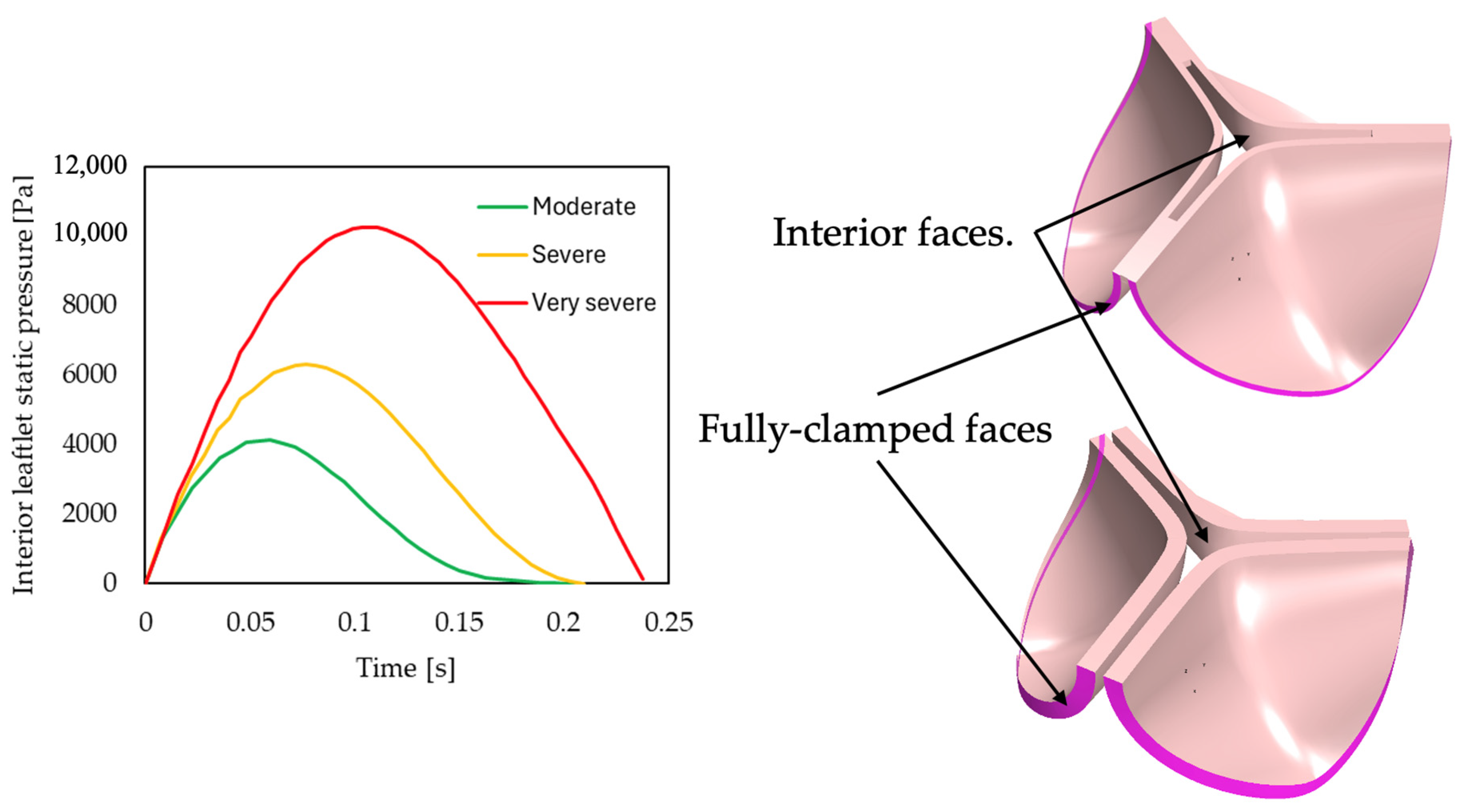
In the present work, rheumatic and calcific affected aortic heart valves are investigated at fully open conditions. Rheumatic aortic valve disease (RAVD) causes lesions on the valve leaflets that result in fusion at the commissures [19]. Calcific aortic valve disease (CAVD) progression is characterized by increased thickening of the valve leaflets due to calcium deposits [20]. To generate 3D fully open geometries that characterise these conditions, non-linear FE simulations were performed. A generic aortic heart valve leaflet geometry [21] was used as a base model and then manipulated to replicate RAVD and CAVD. For RAVD cases, the valve leaflets were manually fused at the base of the valve to replicate the morphology, and for the CAVD cases, the leaflets were uniformly thickened. Utilizing these manipulated valve geometries, an FE solver was then employed in conjunction with dynamic pressure waveforms for moderate, severe, and very severe aortic stenosis to determine the respective open geometries. These pressure waveforms were generated using the LPM proposed by Laubscher et al. [14], along with clinical systole area opening ratio values ( A R = A V A / A L V O T ), where A L V O T is the root area of the aortic valve). To ensure that the FE model-predicted AR values corresponding to the clinical values for the various degrees of stenosis, a manual iterative process was followed where fusion lengths and leaflet thicknesses were adjusted until the desired values were achieved. The pressure waveforms used to deform the valves are shown in Figure 1 below along with the moderate RAVD and CAVD undeformed geometries.
Seeing as the focus of the current work is not the FE simulations, only a brief discussion of the modelling setup will be provided here. The Star CCM+ FE solver was used for structural simulations. The simulations utilise an implicit unsteady temporal solver scheme with adaptive time-stepping which for the current setup is controlled by the maximum vertex displacement with a threshold of half the leaflet thickness. The leaflet material is modelled using a hyperelastic Neo-Hookean model. The use of the Neo-Hookean model is appropriate to model hyperelastic materials such as the aortic heart valve. However, as the aortic valve calcifies, its elasticity decreases where the use of other, more complex, material models might be more appropriate. For the purpose of this study, the use of the Noe-Hookean model was deemed sufficient seeing as the goal of the of work is to specifically investigate the haemodynamics given certain AR values. Moreover, it is one of the models used in the literature to model heart valves and arteries [22].
The bulk modulus, material density and c10 parameter were set to 53 MPa, 1000 kg/m3, and 0.1666 MPa, respectively [23]. As previously mentioned, the pressure waveforms were applied as uniform pressure load boundary conditions to the leaflet interior surfaces. As for the valve leaflet base faces, a fully clamped boundary condition is applied.
The geometric valve results from the FE simulations are summarised in Table 1. Furthermore, Figure 2 shows the displacement contours for the various disease morphologies and degrees of severity simulated. The results below indicate that the AR values for the two morphologies correspond reasonably well with each other. However, significant differences are observed in the calculated hydraulic diameters (Dh) between the RAVD and CAVD cases, attributed to variations in perimeters. The contour plots of leaflet displacements reveal that RAVD results in relatively round or typical orifice-shaped holes. In contrast, the CAVD cases exhibit holes with a circular three-pronged shape, leading to a larger perimeter and, consequently, a smaller hydraulic diameter.
According to the AHA/ACC and ESC/EACT guidelines, the AVA is 1–1.5 cm2 for moderate stenosis, and less than 1 cm2 for severe and very severe stenosis. Therefore, the AR results summarised in Table 1 are in accordance with the guidelines, and, for the purposes of this study, considered an accurate representation of the respective pathological valve conditions [3,4].

2.2. Empirical Models

As mentioned, three empirical models are applied in the current work, namely the constant CQ model from Korakianitis and Shi, 1D model from Laubscher et al. and the clinical correlation model.

2.2.1. Korakianitis and Shi CQ-Model

In 2006, Korakianitis and Shi [18] developed a model where the heart valves are modelled as concentrated parameter components, and the valve dynamics are derived through consideration of the forces acting in on it. The model was used to yield the cardiovascular behaviour for regurgitant aortic valves. The pressure drop for a given volumetric flow rate Q a o   [ m l s ] through the valve is calculated using Equation (1). In Equation (1), C Q  is the constant valve flow coefficient of 350 [ m L s · m m H g 0.5 ], A R the opening area ratio, and P l v and P s a s the left ventricular and systemic aortic sinus pressures [ m m H g ], respectively. From Equation (1), it is evident that this approach is insensitive to valve disease morphology as the C Q flow coefficient remains constant for all valve morphologies and severities.
P l v P s a s = P a o = Q a o C Q · A R 2

2.2.2. Laubscher et al. 1D-Model

In 2022, Laubscher et al. [14] developed a LPM model to improve the applicability of LPMs to a wider range of geometric and haemodynamic parameters for different valvular disease morphologies. The pressure gradient (drop) across the heart valve P a o is calculated using Equation (2). Here, the total loss coefficient ( K t ) is the sum of the contraction loss coefficient ( K c ) in Equation (3), the frictional loss coefficient ( K f ) in Equation (4), and the sudden expansion loss coefficient ( K s e ) in Equation (7).
P a o = ρ · K t 2 · 133 . 3 ˙ Q a o · 10 6 A L V O T · A R 2
In the current work, the left ventricular outflow tract (LVOT) area is taken as A L V O T = 444.8   [ m m 2 ] , ρ = 995   [ k g m 3 ] , and peak systole A R for each valve is summarised in Table 1.
K c = 0.0696 · sin α 1 β 5 λ 2 + λ 1 2
For Equation (3), α = π 2 θ v , β = A R and the contraction ratio λ = 1 + 0.622 α 180 4 5 1 0.215 β 2 0.785 β 5 , where θ v is the valve opening angle relative to the adjacent heart chamber.
K f = f ( 1 β 4 ) 8 · s i n ( α 2 ) + β 4 f · H c u s p 0.5 ( L V O T + d A V A )
In Equation (4), H c u s p = 17.5 m m is the height of the leaflet cusps, L V O T = 23.8   [ m m ] the length of the outflow tract, and d A V A = 4 · A R · A L V O T P   [ m m ] the aortic valve flow area hydraulic diameter with the perimeter P , which is summarised in Table 1. The Colebrook–White equation in Equation (5) is used to calculate the friction factor f .
1 f = 2 · log 10 2.51 R e f
The Reynolds number is calculated according to Equation (6) with the velocity in the valve estimated by v = Q a o A L V O T A R m s and the dynamic viscosity μ = 0.0035 P a · s .
R e = ρ · v · d A V A μ
For the sudden expansion loss coefficient in Equation (7), β 2 = d A V A d w a l l ,  where d w a l l = 30.2 m m .
K s e = 1 β 2 2 2
Of all the parameters included in the 1D modelling approach, following a sensitivity analysis of the pressure drop to these parameters, it was found that the model is most sensitive to variations in the diameter of the LVOT and the artery wall and the dynamic viscosity ( μ ) .

2.3. Clinical Approach

According to the European Society of Cardiology (ESC)/European Association for Cardio-Thoracic Surgery (EACTS) [3] and the American College of Cardiology (ACC)/American Heart Association (AHA) [4] guidelines on the management of patients with VHD, the preferred procedure for estimating valvular pressure gradient is using Doppler echocardiography and a mathematical correlation derived from the Bernoulli equation [3,4,6]. The Bernoulli equation assumes steady flow along a streamline and illustrates the relationship between pressure difference and velocity across a heart valve. It has been shown that the convective term dominates blood flow acceleration across the valve, and thus viscous losses can be neglected at the area of the jet at peak velocity, resulting in the simplified Bernoulli equation in Equation (8). Here, P a o [ m m H g ] is the pressure drop across the valve and v m a x   m s is the peak jet velocity.
Δ P a o = 4 · v m a x 2
The coefficient of 4 in Equation (8) is derived from the equation for dynamic pressure and estimated due to the density of blood and the conversion from Pascal to mmHg. The dependence of the pressure gradients on the maximum flow velocity is evident from Equation (8). The manner in which the peak systolic velocity is determined depends on various factors, including beam alignment, trace accuracy, and the experience of the operator. Furthermore, the vena contracta (VC) of fluid flow does not necessarily correspond to the smallest valve area (AVA). It is located at the effective orifice area (EOA) of the valve, the downstream area of peak velocity obtained from the mass balance across the valve. The importance of measuring the true peak velocity of the valve is discussed in Section 3.

2.4. Computational Fluid Dynamics Models

For the CFD simulations performed in the current work, the Reynolds-averaged steady-state incompressible form of the mass and momentum equations in Equation (9) are solved.
· U ¯ = 0 ρ · U ¯ U ¯ = p ¯ + · τ ̿ ρ U U ¯ + S ¯
In Equation (9), U = u ¯ i + v ¯ j + w ¯ k is the velocity vector in the x, y and z direction, ρ is the density of blood, p is the static pressure, and S ¯ = ρ g ¯ + F ¯ is the source term. The stress tensor τ ̿ is given by Equation (10) below.
τ ̿ = μ U + U T 2 3 · U I
Even though blood has non-Newtonian traits, it is reasonable to assume it to exhibit Newtonian behaviour for blood vessels larger than 0.5 mm where the non-Newtonian viscosity can be disregarded [9,10,24,25,26]. The properties of blood are therefore assumed to be constant with a density of ρ = 995   [ k g m 3 ] and dynamic viscosity of μ = 0.0035 P a · s [27,28]. The time-dependent flow fluctuations can be solved through direct numerical simulation (DNS) techniques, large eddy simulation (LES), or Reynolds-averaged Navier–Stokes equations (RANS). In the momentum Equation (9), the Reynolds stresses that arise from the Reynolds averaging of the fundamental mass and momentum equations are closed using a turbulence model and Equation (11).
ρ U U ¯ = μ t U + U T 2 3 ρ k δ k k
In Equation (11), the Reynolds stresses are computed using the Boussinesq expression, where μ t   P a · s is the eddy viscosity, k = 1 2 ( u 2 ¯ + v 2 ¯ + w 2 ¯ ) is the kinetic energy, and δ k k the Kronecker delta [29]. In the present work, two RANS modelling approaches were applied, namely the k ε and k ω turbulence models. The Shear-Stress Transport (SST) k ω turbulence model is based on the empirical model transport equations for the turbulent kinetic energy ( k ) and the specific dissipation rate ( ω ) and used in flows with adverse pressure gradients [30]. For the SST k ω turbulence model, the eddy viscosity is calculated as μ t = ρ k ω . For the k ε method, μ t = ρ C μ k 2 ε , where C μ is a dimensionless constant.
The meshing of all geometric models discussed in Section 2.1 is performed using ANSYS Fluent’s Watertight Meshing Tool (ANSYS Inc., Canonsburg, PN, USA). The fluid domain is discretised to create surface and volume meshes to enable CFD simulations. Poly hex-core elements are created with an additional cylindrical body of influence dictating reduced cell size and increased boundary layer thickness around the valve. A mass-flow inlet, constant pressure outlet of 0 Pa, and no-slip conditions on all walls are specified for each simulation. A pressure-based solver is used to solve the steady incompressible flow problems. For this approach, the velocity field is obtained from the momentum equations and the pressure term through manipulation of both the continuity and the momentum equations with a pressure correction term. SIMPLE pressure-velocity coupling scheme is used with momentum-based Rhie–Chow flux type and Green–Gauss node-based spatial discretisation. Convergence is assumed when the scaled residuals remain below 10−4 for the continuity, momentum, and turbulence equations.

3. Results and Discussion

CQ, 1D, clinical and CFD models for all six cases (moderate, severe, and very severe rheumatic and calcific, respectively) of AS are developed and simulated according to the same methodology as described in Section 2 to obtain the results discussed in this section. Throughout the discussion of the results, the clinical approximation refers to the simplified Bernoulli approach described in Section 2.3 as it is what is used in clinical practice. Further, the CFD model is considered ground truth to compare the other methods to as no patient data were used in the current work.

3.1. Mesh Independence Study

A mesh or grid independence study is important to consider when developing 3D CFD models to determine the degree to which the solution is affected by the mesh density. The solution is regarded as independent or insensitive to the mesh when the average cell size as well as the spatial discretization error approaches zero. For each case of AS, the valvular pressure difference and the peak jet velocity at the valve hydraulic diameter are estimated and the results of three to four mesh variations are compared. Linear extrapolation is used to determine the respective metric at an infinitely fine mesh.
For the rheumatic stenosed valve cases, meshes with sizes between 1.4 and 2.2 million cells are required to reach mesh convergence. For these cases, pressure drop errors ranged from 0.08% for very severe rheumatic stenosis to 1.15% for severe rheumatic stenosis. Larger meshes are required to reach mesh convergence in the calcific stenosis cases ranging from 8 to 8.1 million cells with pressure drop errors ranging from 0.4% for severe calcific stenosis to 0.8% for very severe calcific stenosis cases. In all cases, relative errors between mesh variations reached a maximum pressure difference error of 1.9% for the severe calcific valve. The results of the mesh independence study are summarised in Table 2. All results are rounded up to two decimal places. Based on the mesh independent results, the final meshes for each case was determined for errors below 1%, and the mesh quality for each of the final meshes are also included in Table 2.

3.2. Turbulence Modelling

The most common models used in modelling blood flow through the aortic valve are two-equation RANS models, more specifically, the SST k ω and k ε turbulence models [9,31]. The use of the k ω turbulence model in steady-state CFD models was demonstrated using CT data of a native valve in 2020 by Hoeijmakers et al. [9] and using 4D flow MRI data of a prosthetic valve in 2021 by Hellmeier et al. [25]. For these models, the turbulence intensity was set to 5%, and a velocity profile inlet and zero pressure outlet BC and rigid walls was used to determine the transaortic pressure gradients. For the native valve, CFD simulations were used as the reference pressure drop when analysing the performance of meta-models which yielded root mean squared errors (when more than 300 training points were considered) of 1.7 mmHg. For the prosthetic valve, the CFD flow field were compared to postoperative data and found that the CFD simulations approximated a maximum pressure drop of 12 mmHg compared to the 18 mmHg MRI estimation.
The k ε turbulence model was used in 2020 by Franke et al. [31], where a steady-state CFD model was developed to evaluate the transvalvular pressure gradient in patient specific geometries of stenotic aortic valves. The results from the CFD flow field were used as ground truth when determining the accuracy of their model-predicted pressure drops, and to the pressure drop estimated by the Bernoulli model. The use of the k ε turbulence model is further demonstrated in the work done by Heys et al. in 2010 [32].
To determine which turbulence model to use to accurately estimate the turbulent flow patterns of blood through pathological aortic heart valves, these two turbulence models were used, and the results were analysed for a steady valve inlet volume flow rate of 600 mL/s. For the chosen independent meshes in Section 3.1, an SST k ω model with low Reynolds dissipation and a standard k ε model with enhanced wall treatment are compared and the results are summarised in Table 3. For all cases, the k ε model estimated slightly greater pressure gradients compared to the SST k ω model and was therefore chosen as the turbulent model to be used in all further simulations. The SST k ω method is most widely used when studying heart valve flow, but it often has the disadvantage associated with the difficulty to overcome the sensitivity of this model to the freestream values of k and ω , where the k ε model is robust in that regard [9,25,30].
The pressure drop results summarised in Table 3 are not to be taken as a realistic representation of the pressure drop one would expect to measure across the respective pathological valves. This is due to the over exaggeration of the inlet volume flow rate for the purpose of analysing the performance of the CFD model at high resultant pressure and velocity gradients.

3.3. Steady State Simulations

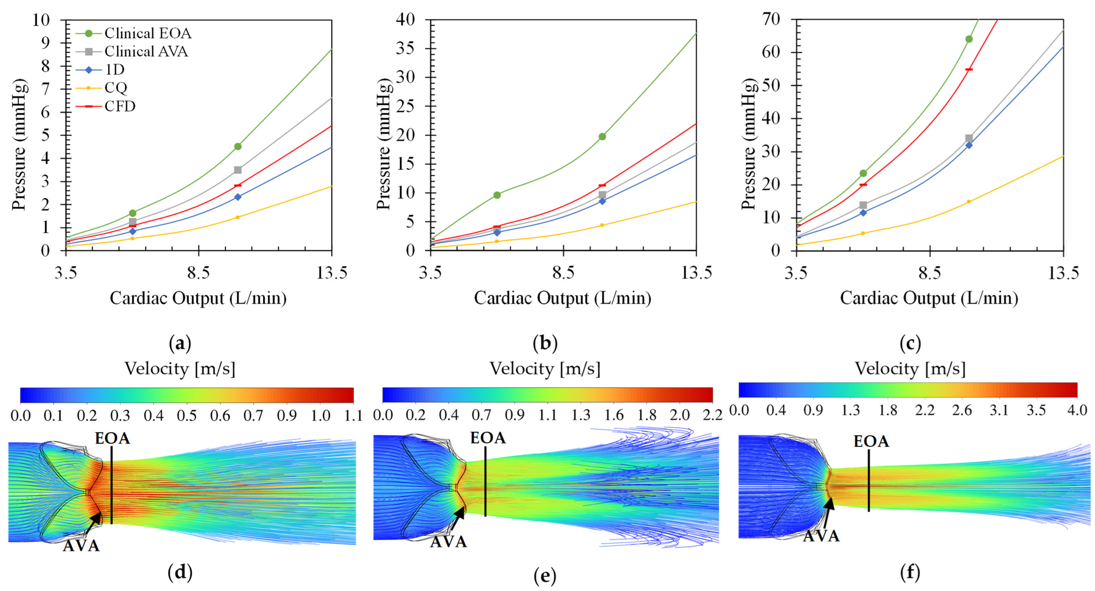
Figure 3 shows the different pressure drop versus cardiac output (CO) for the different modelling equations of rheumatic aortic stenosis (a–c) and the velocity streamline plots (d–f) at 10 L/min CO. From these plots, the effect of varying CO on the transvalvular pressure gradient and the velocity field can be analysed. For all cases, the pressure drop increases quadratically, as expected, with an increase in CO and disease severity. Moreover, the clinical estimation at the EOA results in the largest observed pressure drops, and the CQ model estimates the smallest pressure drops. The difference between the results from the two clinical pressure estimation methods grows for increasing severity. The average percentage difference between the pressure drops calculated through the clinical estimation method at the EOA and the AVA is approximately 45%. This indicates that the maximum blood flow velocity magnitude shifts further away from the value calculated at the AVA, which is expected from typical orifice-like flow fields at higher Reynolds numbers and indicated in Figure 3d–f. Therefore, using the velocity at the AVA would result in significant underprediction of the pressure drop at very severe conditions when comparing to the CFD results as ground truth.
The clinical estimation at the AVA is, on average, 18% larger than the CFD results for a moderately stenosed rheumatic valve, 15% smaller than the CFD results in a severe rheumatic stenosed valve, and 36% smaller than the CFD estimations in the very severe rheumatic stenosed valve. The clinical estimation at EOA produces results with errors of 50% for moderate, 78% for severe, and 16% for very severe cases compared to the CFD results. This suggests the inconsistent behaviour of the clinical pressure drop calculation compared to the CFD result, especially when the maximum velocity of the valve is measured at the AVA.
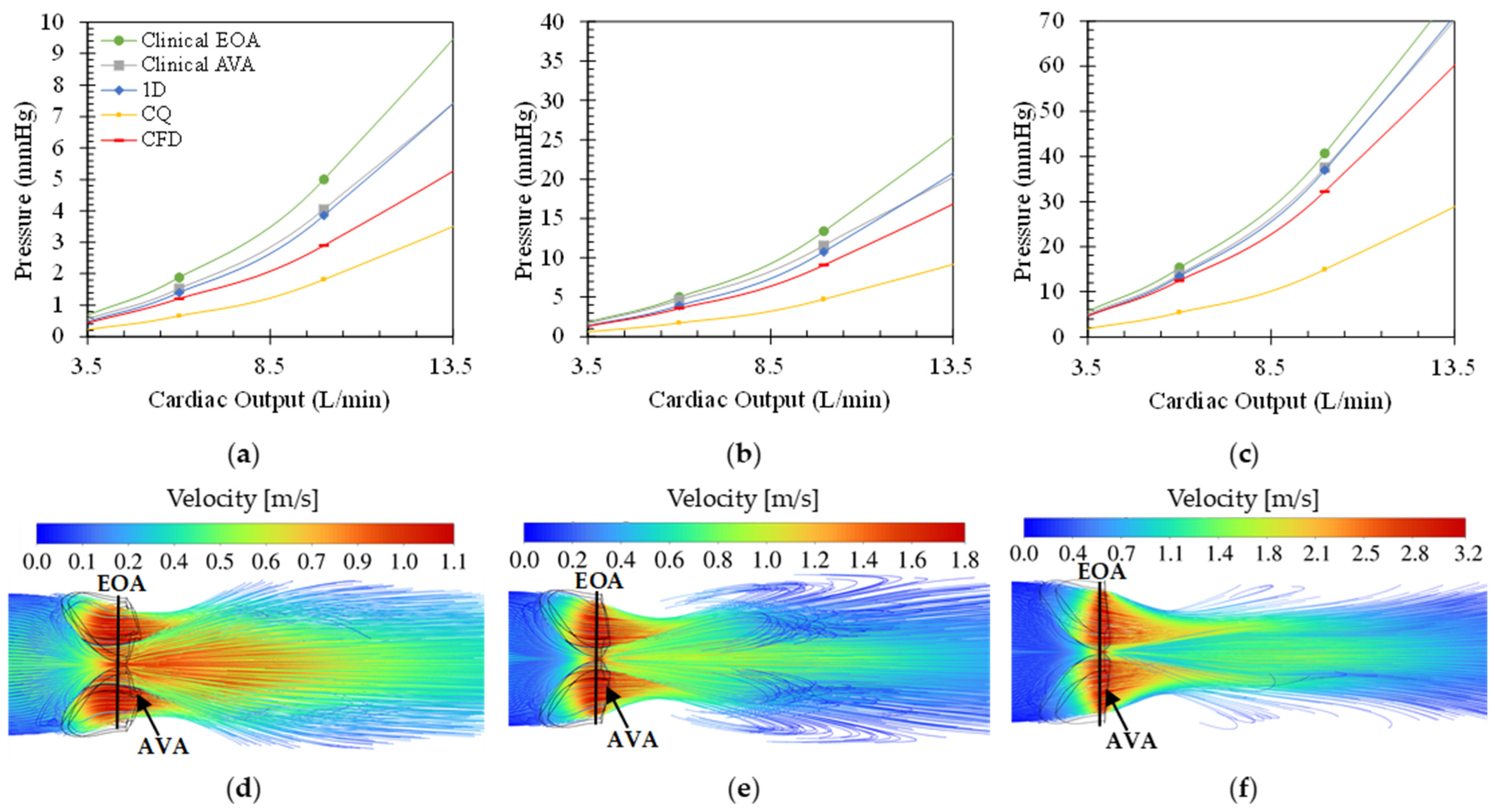
Figure 4 shows the effect of varying CO on the transaortic pressure drop (a–c) for the different modelling equations as well as the velocity contour plots (d–f) at 10 L/min CO of varying degrees of calcific stenosis. Similar to Figure 3, the pressure drops over the valve increases for increasing CO and disease severity. In all cases, the clinical pressure estimation at flow VC (or EOA) produced the highest and the CQ model the lowest pressure drop over the valve with maximum pressures of 158 mmHg for the very severe calcific case at 20 L/min CO. For all three calcific cases, both the clinical models as well as the 1D model estimated pressure gradients greater than the CFD findings. Both the clinical model at the AVA and the 1D model follow the same trend throughout, as expected.
The difference between the two clinical pressure estimations decreases for increasing severity with a maximum average difference of 20% in the moderate calcific case and a minimum of 10% in the very severe calcific case. At the AVA, the pressure estimation is larger than that of the CFD, with errors decreasing with increasing severity of 32%, 26%, and 12% for moderate, severe, and very severe cases, respectively. The same trend is followed by the clinical pressure estimations at the EOA, with errors of 61%, 41%, and 23% for moderate, severe, and very severe calcific valves. These results show that the clinical correlation follows a more predictable trend for cases of calcific stenosis compared to rheumatic stenosis, emphasising the need for a morphology-dependent clinical correlation.
From Figure 4d–f, the location of the flow VC is located in closer proximity to the AVA, implying that the EOA is located inside the valve at the AVA. This explains the decreasing error between the two clinical models with increasing severity.
The average CO of a healthy male at rest is 5–6 L/min and 35 L/min during exercise [33]. Over a CO range of 3.5 L/min–10 L/min, the range of pressure drops calculated through each approach is summarised in Table 4. Here, the differences between each model and the ground-truth CFD results are shown.
Comparing the results in Figure 3 and Figure 4 and Table 4, it can be argued that the clinical approach both under- and overestimates the pressure drop in the case of rheumatic aortic stenosis, depending on the severity of the disease, and consistently overestimates pressure drops in all the calcific aortic stenosis cases. The 1D model follows the same trend as the clinical approach where the over- or underestimation depends on the disease type and severity. For both pathologies, the CQ model produces underestimated pressure drop results with the highest errors. This is as expected due to its insensitivity to disease type and morphology. Lastly, the flow location of peak velocity is outside, distal to the rheumatic valve and inside, close to the smallest valve diameter, in the calcific valve. These results reveal that various morphologies yield distinct non-linear relationships between CO and pressure drop, emphasizing the need for further investigation.
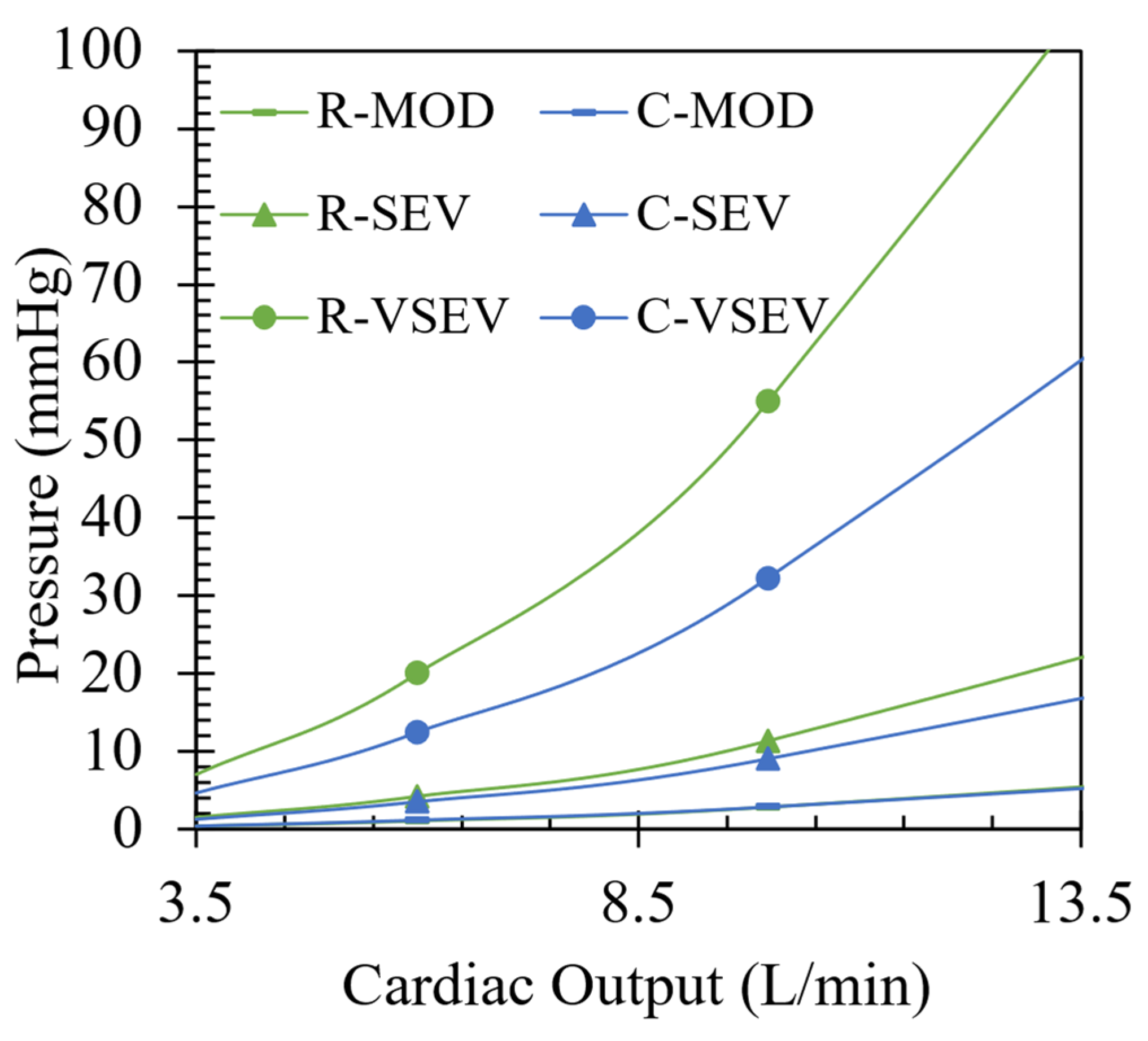
In Figure 5, the CFD results are illustrated for each case of rheumatic and calcific aortic stenosis over a range of CO. For all cases of rheumatic AS, higher transvalvular pressure gradients compared to the calcific AS cases are illustrated. The results follow a trend of increasing pressure differences between the two pathologies for increase in severity. The average difference in pressure gradients between the two pathologies are 0.08 mmHg, 1 mmHg, and 22.68 mmHg for moderate, severe, and very severe cases, respectively, with an absolute maximum of 22.68 mmHg at 10 L/min for the very severe case. To better understand why there is a distinct difference in pressure gradients between two types of valve lesions with the same severity, entropy production in the domain is analysed in Section 3.4.

3.4. Entropy Generation for Different Pathologies and Severities at 10 L/min CO

Entropy generation is a useful flow domain property when one wants to pinpoint the positions of where useful work is lost. From the well-known T d s relation for isothermal incompressible flow, the change in entropy is directly related to the change in pressure in Equation (12).
d s = 1 ρ T d P
Entropy is generated through fluid irreversibilities such as friction, mixing, heat transfer, and expansion. Therefore, entropy generation provides insights into the irreversibility of a process [34]. As blood accelerates through a constriction such as a pathological aortic heart valve, entropy is generated mainly due to laminar and turbulent viscous dissipation. The driving factor(s) for the transvalvular pressure gradients of each respective pathology seen in Figure 3, Figure 4 and Figure 5 can be identified through the analysis of regions where entropy generation is dominant.
For a system where only entropy generation by dissipation ( Φ ) is relevant as no heat transfer is present, the entropy balance equation reduces to Equation (13) for instantaneous entropy s , velocities u , v , and w , and temperature T .
ρ s t + u s x + v s y + w s z = Φ T
Instantaneous values of entropy production by dissipation in turbulent flow scenarios are described by a time-average part ( S D ¯ ) and a fluctuating part ( S D ) as in Equations (14) and (15). Here, S D ¯ represents the entropy production in the mean flow field, and S D in the fluctuating or turbulent field where μ and ρ are the dynamic viscosity and density of blood, respectively, and ε the turbulent dissipation rate of the k ε turbulence model [35]. Equations (14) and (15) are implemented during the post-processing phase of the CFD simulations for each rheumatic and calcific case at 10 L/min CO. The entropy production is calculated and the regions of interest identified from 3D streamline plots in Figure 6, Figure 7 and Figure 8.
Φ ¯ T = S D ¯ + S D
S D ¯ = μ T ¯ 2 u ¯ x 2 + v ¯ y 2 + w ¯ z 2 + u ¯ y + v ¯ x 2 + u ¯ z + w ¯ x 2 + v ¯ z + w ¯ y 2
S D = ρ ε T ¯
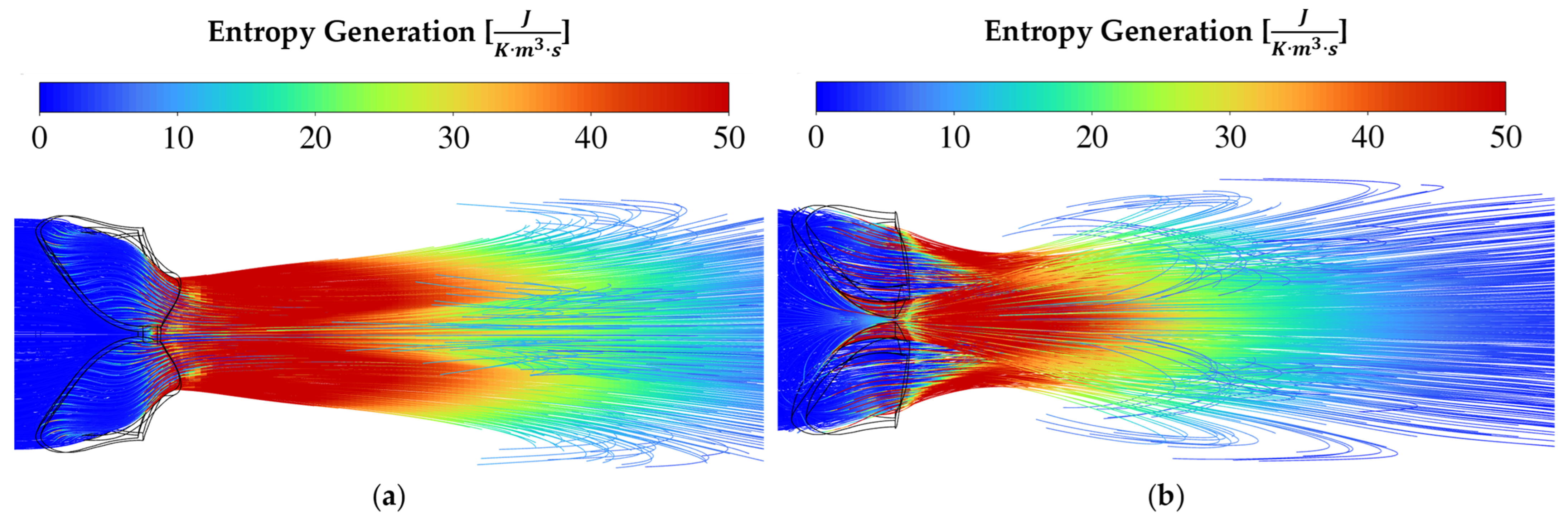
For rheumatic AS in Figure 6a, Figure 7a and Figure 8a, the valve area reduction more closely resembles that of an orifice, even though the shape is not perfectly circular. The mechanism of pushing the blood through the reduced valve area is by contraction and therefore friction at the valve walls, as seen by the increase in entropy intensity proximal to the AVA. Immediately distal to the valve, the flow starts to expand. The flow starts to break away and recirculate downstream from the EOA. It is evident from the entropy generation representation that the sudden expansion effect dominates as the driving factor causing a pressure drop across the valve.
In the calcific AS cases of Figure 6b, Figure 7b and Figure 8b, sudden contraction and friction play a larger role than in the rheumatic cases, while sudden expansion still dominates. When considering the results for the calcific valves in Figure 4, the constant overestimation of the pressure drops using the 1D and clinical approaches can be attributed to an overestimation of the sudden expansion coefficient. From the results in this section, it seems plausible to argue that the main contributing factor to transvalvular pressure drop is expansion loss distal to the valve, similar to what was found by Laubscher et al. [14].
As seen in Figure 5, the pressure drops for moderate and severe conditions are relatively similar. Therefore, the intensity and size of the high entropy generation regions are expected to be similar, as seen in Figure 6 and Figure 7. For the very severe case, a large difference is observed between the two pathologies, which is substantiated if one studies the entropy production magnitudes in Figure 8.
In the streamline plots above, it is seen that the rheumatic jet expansion zone is noticeably larger compared to the high entropy production zone of the calcific case. This is due to the larger high velocity jet core zone that exists in the rheumatic valve, resulting in larger magnitudes of shear stresses and, in turn, more dissipation and entropy production translating into a higher pressure drop.
To demonstrate that the majority of the lost work originates from turbulent dispersion downstream of the valve, the total entropy generated within the valve (proximal) and downstream (distal) was calculated using the CFD simulation results. Table 5 presents the percentage difference between distal and proximal total entropy generation for rheumatic cases, ranging from moderate to very severe, increasing from 2068% to 8006% relative to proximal entropy generation. Therefore, the primary source of entropy generation lies distal to the valve due to the sudden expansion effects. In the calcific case, it is observed that the same percentage differences decrease from 748% to 735% as the severity progresses from moderate to very severe. This suggests that, compared to rheumatic cases, a smaller portion of entropy is generated distally.
4. Conclusions

The results show that the pressure gradient across pathological aortic heart valves varies depending on the type and severity of the valve lesion. These differences in pressure drop between rheumatic and calcific valves can be attributed to the distinct difference in shape and size of the valve opening area. Through the analysis of entropy production in the flow domain, the dominant parameters in initiating adverse valvular pressure gradients are identified. These findings elucidate why the pressure drop in rheumatic valves are consistently higher than that in calcific valves. The results further show the underpredicting nature of generic numerical models, such as the CQ model, due to its insensitivity to disease morphology. Even though the clinical approach is based on empirical data, the inconsistent results obtained, especially in the rheumatic case, necessitates further investigation into the insensitivity of this approach to disease type and morphology. The fluid model assumed steady inflow conditions at peak systole, rigid walls, and constant outflow boundary conditions. Fluid–structure interaction and compliant wall conditions are outside the scope of the current work; however, the need to investigate the flow conditions through pathological aortic valves using more complex 3D modelling is apparent.

Author Contributions

Conceptualization, L.G., R.L., J.v.d.M. and P.G.H.; methodology, L.G. and R.L.; software, L.G. and R.L.; validation, L.G. and R.L.; formal analysis, L.G.; investigation, L.G. and R.L.; resources, L.G., R.L. and P.G.H.; data curation, L.G. and R.L.; writing—original draft preparation, L.G.; writing—review and editing, L.G., R.L., J.v.d.M. and P.G.H.; visualization, L.G. and R.L.; supervision, R.L., J.v.d.M. and P.G.H.; project administration, L.G. and R.L.; funding acquisition, L.G. and R.L. All authors have read and agreed to the published version of the manuscript.

Funding

This work is based on the research supported in part by the National Research Foundation of South Africa (reference number PMDS22071138485).

Data Availability Statement

The original contributions presented in the study are included in the article, further inquiries can be directed to the corresponding author.

Conflicts of Interest

The authors declare no conflicts of interest.

References

  1. Rozeik, M.M.; Wheatley, D.J.; Gourlay, T. The aortic valve: Structure, complications and implications for transcatheter aortic valve replacement. Perfusion 2014, 29, 285–300. [Google Scholar] [CrossRef] [PubMed]
  2. Mohrman, D.E.; Heller, L.J. Author. In Cardiovascular Physiology, 9th ed.; McGraw-Hill Education: New York, NY, USA, 2018; Available online: https://accessmedicine.mhmedical.com/content.aspx?bookid=2432&sectionid=190800315 (accessed on 8 May 2023).
  3. Vahanian, A.; Beyersdorf, F.; Praz, F.; Milojevic, M.; Baldus, S.; Bauersachs, J.; Capodanno, D.; Conradi, L.; De Bonis, M.; De Paulis, R.; et al. 2021 ESC/EACTS Guidelines for the management of valvular heart disease. Eur. Heart J. 2022, 43, 561–632. [Google Scholar] [CrossRef] [PubMed]
  4. Otto, C.M.; Nishimura, R.A.; Bonow, R.O.; Carabello, B.A.; Erwin, J.P., III; Gentile, F.; Jneid, H.; Krieger, E.V.; Mack, M.; Writing Committee Members; et al. 2020 ACC/AHA Guideline for the Management of Patients With Valvular Heart Disease. J. Am. Coll. Cardiol. 2021, 77, e25–e197. [Google Scholar] [CrossRef] [PubMed]
  5. Brown, J.; Morgan-Hughes, N.J. Aortic stenosis and non-cardiac surgery. Contin. Educ. Anaesth. Crit. Care Pain 2005, 5, 1–4. [Google Scholar] [CrossRef]
  6. Hatle, L.; Brubakk, A.; Tromsdal, A.; Angelsen, B. Noninvasive assessment of pressure drop in mitral stenosis by Doppler ultrasound. Heart 1978, 40, 131–140. [Google Scholar] [CrossRef] [PubMed]
  7. Currie, P.J.; Seward, J.B.; Reeder, G.S.; Vlietstra, R.E.; Bresnahan, D.R.; Bresnahan, J.F.; Smith, H.C.; Hagler, D.J.; Tajik, A.J. Continuous-Wave Doppler Echocardiographic Assessment of Severity of Calcific Aortic Stenosis: A Simultaneous Doppler-Catheter Correlative Study in 100 Adult Patients. Circulation 1985, 71, 1162–1169. [Google Scholar] [CrossRef] [PubMed]
  8. Harris, P.; Kuppurao, L. Quantitative Doppler echocardiography. BJA Educ. 2016, 16, 46–52. [Google Scholar] [CrossRef]
  9. Hoeijmakers, M.J.M.M.; Waechter-Stehle, I.; Weese, J.; Van de Vosse, F.N. Combining statistical shape modeling, CFD, and meta-modeling to approximate the patient-specific pressure-drop across the aortic valve in real-time. Int. J. Numer. Methods Biomed. Eng. 2020, 36, e3387. [Google Scholar] [CrossRef] [PubMed]
  10. Casas, B.; Lantz, J.; Dyverfeldt, P.; Ebbers, T. 4D Flow MRI-based pressure loss estimation in stenotic flows: Evaluation using numerical simulations. Magn. Reson. Med. 2016, 75, 1808–1821. [Google Scholar] [CrossRef]
  11. Hose, D.R.; Lawford, P.V.; Huberts, W.; Hellevik, L.R.; Omholt, S.W.; van de Vosse, F.N. Cardiovascular models for personalised medicine: Where now and where next? Med. Eng. Phys. 2019, 72, 38–48. [Google Scholar] [CrossRef]
  12. Laadhari, A.; Quarteroni, A. Numerical modeling of heart valves using resistive Eulerian surfaces. Int. J. Numer. Methods Biomed. Eng. 2015, 32, e02743. [Google Scholar] [CrossRef] [PubMed]
  13. Black, S.M.D.; Maclean, C.; Barrientos, P.H.; Ritos, K.; McQueen, A.; Kazakidi, A. Calibration of patient-specific boundary conditions for coupled CFD models of the aorta derived from 4D Flow-MRI. Front. Bioeng. Biotechnol. 2023, 11, 1178483. [Google Scholar] [CrossRef] [PubMed]
  14. Laubscher, R.; van der Merwe, J.; Liebenberg, J.; Herbst, P. Dynamic simulation of aortic valve stenosis using a lumped parameter cardiovascular system model with flow regime dependent valve pressure loss characteristics. Med. Eng. Phys. 2022, 106, 103838. [Google Scholar] [CrossRef] [PubMed]
  15. Pase, G.; Brinkhuis, E.; De Vries, T.; Kosinka, J.; Willems, T.; Bertoglio, C. A parametric geometry model of the aortic valve for subject-specific blood flow simulations using a resistive approach. Biomech. Model. Mechanobiol. 2023, 22, 987–1002. [Google Scholar] [CrossRef] [PubMed]
  16. Van Aswegen, K.H.J.; Smuts, A.N.; Scheffer, C.; Weich, H.S.V.; Doubell, A.F. Investigation of leaflet geometry in a percutaneous aortic valve with the use of fluid-structure interaction simulation. J. Mech. Med. Biol. 2012, 12, 1250003. [Google Scholar] [CrossRef]
  17. Kaiser, A.D.; Shad, R.; Hiesinger, W.; Marsden, A.L. A design-based model of the aortic valve for fluid-structure interaction. Biomech. Model. Mechanobiol. 2021, 20, 2413–2435. [Google Scholar] [CrossRef] [PubMed]
  18. Korakianitis, T.; Shi, Y. Numerical simulation of cardiovascular dynamics with healthy and diseased heart valves. J. Biomech. 2006, 39, 1964–1982. [Google Scholar] [CrossRef] [PubMed]
  19. Afifi, A.; Hosny, H.; Yacoub, M. Rheumatic aortic valve disease-when and who to repair? Ann. Cardiothorac. Surg. 2019, 8, 383–389. [Google Scholar] [CrossRef]
  20. Rajamannan, N.M.; Evans, F.J.; Aikawa, E.; Grande-Allen, K.J.; Demer, L.L.; Heistad, D.D.; Simmons, C.A.; Masters, K.S.; Mathieu, P.; O’Brien, K.D.; et al. Calcific aortic valve disease: Not simply a degenerative process: A review and agenda for research from the national heart and lung and blood institute aortic stenosis working group. Circulation 2011, 124, 1783–1791. [Google Scholar] [CrossRef]
  21. Kouhi, E.; Morsi, Y.S. A parametric study on mathematical formulation and geometrical construction of a stentless aortic heart valve. J. Artif. Organs 2013, 16, 425–442. [Google Scholar] [CrossRef]
  22. Owen, B.; Bojdo, N.; Jivkov, A.; Keavney, B.; Revell, A. Structural modelling of the cardiovascular system. Biomech. Model. Mechanobiol. 2018, 17, 1217–1242. [Google Scholar] [CrossRef] [PubMed]
  23. Spühler, J.H.; Jansson, J.; Jansson, N.; Hoffman, J. 3D fluid-structure interaction simulation of aortic valves using a unified continuum ALE FEM model. Front. Physiol. 2018, 9, 363. [Google Scholar] [CrossRef]
  24. Le, T.B.; Usta, M.; Aidun, C.; Yoganathan, A.; Sotiropoulos, F. Computational Methods for Fluid-Structure Interaction Simulation of Heart Valves in Patient-Specific Left Heart Anatomies. Fluids 2022, 7, 94. [Google Scholar] [CrossRef]
  25. Hellmeier, F.; Brüning, J.; Sündermann, S.; Jarmatz, L.; Schafstedde, M.; Goubergrits, L.; Kühne, T.; Nordmeyer, S. Hemodynamic Modeling of Biological Aortic Valve Replacement Using Preoperative Data Only. Front. Cardiovasc. Med. 2021, 7, 593709. [Google Scholar] [CrossRef] [PubMed]
  26. Luraghi, G.; Migliavacca, F.; García-González, A.; Chiastra, C.; Rossi, A.; Cao, D.; Stefanini, G.; Matas, J.F.R. On the Modeling of Patient-Specific Transcatheter Aortic Valve Replacement: A Fluid–Structure Interaction Approach. Cardiovasc. Eng. Technol. 2019, 10, 437–455. [Google Scholar] [CrossRef]
  27. Yan, W.; Li, J.; Wang, W.; Wei, L.; Wang, S. A Fluid–Structure Interaction Study of Different Bicuspid Aortic Valve Phenotypes Throughout the Cardiac Cycle. Front. Physiol. 2021, 12, 716015. [Google Scholar] [CrossRef] [PubMed]
  28. Vitello, D.J.; Ripper, R.M.; Fettiplace, M.R.; Weinberg, G.L.; Vitello, J.M. Blood Density Is Nearly Equal to Water Density: A Validation Study of the Gravimetric Method of Measuring Intraoperative Blood Loss. J. Vet. Med. 2015, 2015, 152730. [Google Scholar] [CrossRef]
  29. Versteeg, H.K.; Malalasekera, W. An Introduction to Computational Fluid Dynamics Second Edition. Available online: www.pearsoned.co.uk/versteeg (accessed on 20 February 2023).
  30. Ansys ® Fluent Theory Guide, 2022 R1, Help System, ANSYS, Inc. Available online: http://www.ansys.com (accessed on 24 November 2023).
  31. Franke, B.; Weese, J.; Waechter-Stehle, I.; Brüning, J.; Kuehne, T.; Goubergrits, L. Towards improving the accuracy of aortic transvalvular pressure gradients: Rethinking Bernoulli. Med Biol. Eng. Comput. 2020, 58, 1667–1679. [Google Scholar] [CrossRef]
  32. Heys, J.J.; Holyoak, N.; Calleja, A.M.; Belohlavek, M.; Chaliki, H.P. Revisiting the Simplified Bernoulli Equation. Open Biomed. Eng. J. 2010, 4, 123–128. [Google Scholar] [CrossRef]
  33. King, J.; Lowery, D.R. Physiology, Cardiac Output; Updated 17 July 2023; StatPearls: St. Petersburg, FL, USA, 2019. Available online: https://www.ncbi.nlm.nih.gov/books/NBK470455/ (accessed on 14 September 2023).
  34. Çengel, Y.A. Thermodynamics: An Engineering Approach; McGraw-Hill: New York, NY, USA, 2004. [Google Scholar]
  35. Kock, F.; Herwig, H. Entropy production calculation for turbulent shear flows and their implementation in cfd codes. Int. J. Heat Fluid Flow 2005, 26, 672–680. [Google Scholar] [CrossRef]
Figure 1. Valve deformation pressure waveform and moderate undeformed RAVD (top) and CAVD (bottom) geometries.
Mca 29 00033 g001
Figure 2. Rheumatic (top) and calcific (bottom) aortic valve opening area for moderate (a,d); severe (b,e) and very severe (c,f) degrees of stenosis.
Mca 29 00033 g002
Figure 3. Pressure drops over aortic valves with varying degrees of rheumatic stenosis for varying volume flow rates. (a) Moderate, (b) severe, and (c) very severe stenosis. Streamline plots coloured by velocity for (d) moderate, (e) severe, and (f) very severe stenosis.
Mca 29 00033 g003
Figure 4. Pressure drops over aortic valves with varying degrees of calcific stenosis for varying volume flow rates. (a) Moderate, (b) severe, and (c) very severe stenosis. Streamline plots coloured by velocity for (d) moderate, (e) severe, and (f) very severe stenosis.
Mca 29 00033 g004
Figure 5. CFD results for moderate (MOD), severe (SEV), and very severe (VSEV) cases of rheumatic (R) and calcific (C) stenosis and varying CO.
Mca 29 00033 g005
Figure 6. Velocity vector plot for moderate (a) rheumatic and (b) calcific stenosis cases with orthographic views at the top and right-side views at the bottom.
Mca 29 00033 g006
Figure 7. Velocity vector plot for severe (a) rheumatic and (b) calcific stenosis cases with orthographic views at the top and right-side views at the bottom.
Mca 29 00033 g007
Figure 8. Velocity vector plot for very severe (a) rheumatic and (b) calcific stenosis cases with orthographic views at the top and right-side views at the bottom.
Mca 29 00033 g008
Table 1. Pathological aortic valve geometries.
TypeSeverityARPerimeter (mm)Dh (mm)
RheumaticModerate0.394552.1213.47
Severe0.226039.3810.21
Very Severe0.122927.907.84
CalcificModerate0.352276.468.20
Severe0.217963.666.09
Very Severe0.122666.953.22
Table 2. Mesh independence study results for moderate, severe, and very severe cases of rheumatic and calcific aortic valve stenosis.
TypeSeverityCells (×106)ΔP (%error)Final Mesh Cells (×106)Max ARMin Orth
RheumaticModerate2.130.392.741290.12
Severe2.191.152.421430.09
Very Severe1.400.082.731150.05
CalcificModerate8.040.605.38690.13
Severe8.020.405.37640.11
Very Severe7.980.785.33890.17
Table 3. Comparison between turbulence models.
TypeSeverityΔP (mmHg)
SST   k ω k ε
RheumaticModerate34.4535.57
Severe144.56146.43
Very Severe715.78723.37
CalcificModerate33.4534.68
Severe106.09110.67
Very Severe366.61405.75
Table 4. Estimated pressure difference for each case of rheumatic and calcific aortic stenosis for a cardiac output range of 3.5–10 L/min.
TypeSeverityCFD (mmHg)CQ (mmHg)1D (mmHg)Clinical (mmHg)
EOAAVA
RheumaticModerate 0.4–2.80.2–1.40.3–2.30.6–4.50.5–3.5
Severe1.5–11.30.5–4.41.1–8.61.9–19.81.2–9.7
Very Severe7.1–54.91.84–14.94–32.18.27–64.14.3–34.1
CalcificModerate 0.4–2.90.2–1.80.5–3.80.7–50.6–4
Severe1.3–9.10.6–4.71.3–10.81.8–13.41.7–11.6
Very Severe4.7–32.31.8–154.6–375.7–40.75–37.5
Table 5. Total entropy generation upstream (proximal) and downstream (distal) to the valve opening.
TypeSeverity Entropy   Generation   ( × 10 3 W K ) % Difference
Proximal (Upstream)Distal (Downstream)
RheumaticModerate0.0080.1772068%
Severe0.0210.7313426%
Very Severe0.0433.4998006%
CalcificModerate0.0200.166748%
Severe0.0610.539781%
Very Severe0.2191.831735%
Disclaimer/Publisher’s Note: The statements, opinions and data contained in all publications are solely those of the individual author(s) and contributor(s) and not of MDPI and/or the editor(s). MDPI and/or the editor(s) disclaim responsibility for any injury to people or property resulting from any ideas, methods, instructions or products referred to in the content.