Abstract
This paper deals with a parallel hybrid excitation synchronous machine (HESM). First, an expanded literature review of hybrid/double excitation machines is provided. Then, the structural topology and principles of operation of the hybrid excitation machine are examined. With the aim of validating the double excitation principle of the topology studied in this paper, the construction of a prototype is presented. In addition, both the 3D finite element method (FEM) and 3D magnetic equivalent circuit (MEC) model are used to model the machine. The flux control capability in the open-circuit condition and results of the developed models are validated by comparison with experimental measurements. The reluctance network model is created from a mesh of the studied domain. The meshing technique aims to combine advantages of finite element modeling, i.e., genericity and expert magnetic equivalent circuit models, i.e., reduced computation time. It also allows taking the non-linear characteristics of ferromagnetic materials into consideration. The machine prototype is tested to validate the predicted results. By confronting results from both modeling techniques and measurements, it is shown that the magnetic equivalent circuit model exhibits fairly accurate results when compared to the 3D finite element method with a gain in computation time.
1. Introduction
Hybrid excitation synchronous machines (HESMs) are electric machines that use two excitation flux sources: Permanent magnets (PMs) and field coil excitation sources. The association of both excitation sources aims to combine advantages of PM machines and wound field synchronous machines [1]. The good performances of hybrid excitation machines, such as better flux-weakening capability and efficiency, is encouraging an increasing interest for their study. For the generator operating mode, hybrid excitation machines used together in a connection to a diode rectifier constitute an interesting alternative to permanent magnet alternators associated to an active power converter [2,3]. When operating in motor mode, the hybrid excitation principle permits an easier high-speed operation while the use of permanent magnets helps increase the energy efficiency [1]. It is also possible to use the hybrid excitation principle to reduce PM volumes and save material cost. Some comprehensive reviews on hybrid excited topologies can be found in [1] and [3,4,5,6,7,8,9]. An alternative and updated review will be provided in this paper. In addition, in this paper, a parallel hybrid excited machine topology is examined. A 3D magnetic equivalent circuit (MEC) and 3D finite element analysis (FEA) are used to model the HESM and thus, a review on MEC modeling will also be provided in this paper. This machine has permanent magnets on the rotor and field coils in the stator. In order to improve the flux control capability, both the stator and the rotor contain laminated and massive ferromagnetic parts.
The structure and operating principle of this machine are described. In order to validate the hybrid excitation principle a prototype has been built based on requirements provided by a car manufacturer. A magnetic equivalent circuit (MEC) model, based on an original approach, is developed to predict the open circuit flux control capability of the studied machine [10,11,12,13]. This characteristic constitutes a good indicator of the ability of HESM to operate over a large speed range, in particular in the field weakening region [14,15,16,17,18,19]. In addition, MEC models are still widely used for the modeling of electric machines. MEC is suited for pre-design and optimization of electromagnetic devices [20,21,22]. Indeed, this technique helps get simple relations between geometric dimensions, physical properties of materials and machines performance. The goal, in this paper, is to evaluate the use of a 3D MEC model. Based on the approach of reluctance networks modeling [23,24,25,26], the 3D MEC is developed and adapted to the modeling of the studied HESM. The MEC model is generated from a mesh of the studied domain. This technique combines advantages of finite element method (genericity) and expert lumped parameter MEC models, i.e., reduced computation time, while considering non-linear characteristics of ferromagnetic materials. On another hand, the 3D finite element method is also to model the HESM and to predict its performance, while the prototype machine is tested to validate the predicted results.
2. State of The Art of Hybrid Excitation Machines
In scientific and technical literature, several terms are used to qualify electrical machines that use two excitation flux sources:
- Hybrid excitation synchronous machines;
- Double excitation synchronous machines;
- Dual excitation synchronous machines;
- Combined excitation synchronous machines;
- Permanent magnet synchronous machines with auxiliary exciting windings.
Before presenting the operating principles of the studied machine, criteria used for the classification of dual excitation machines are first discussed and an updated review of recently developed hybrid excitation machines will be provided in this section.
2.1. Classification Criteria of Hybrid Excitation Synchronous Machines
A large number of machine topologies structures can be realized when applying the double excitation principle. Therefore, a variety of criteria can be adopted for the classification of double excitation machines. A classical classification criteria used for other types of electric machines can be applied; such as magnetic flux paths as in 2D and 3D structures, linear [27,28] and rotating machines, axial field [18,29,30] and radial field structures. However, with regards to the structural particularity of double excitation machines, i.e., dual excitation flux sources, two criteria seem more appropriate for their classification [6]:
The first criterion is relative to where the excitation sources are located in the machine: Both sources in the stator, both sources in the rotor and mixed localization.
It is meant by mixed localization that one of the sources (excitation coils or permanent magnets) is located in the rotor and the other source in the stator or vice-versa. Having excitation coils in the stator is favored though to avoid sliding contacts [6].
The second is based on the analogy with electrical circuits. From the way the two excitation flux sources are combined, the criterion will be: Series and parallel double excitation machines [1].
It should be highlighted that HESMs are used in a large variety of applications. In [27], authors presented the design of a hybrid excitation linear eddy current brake which could be used in different applications, i.e., vibration suppression, vehicle suspension systems, high-speed train braking systems, transmission systems, etc. In [28], authors presented the design of a hybrid excited linear machine for oceanic wave power generation. While HESM has been first largely studied for transportation applications [1,2,3,16,31,32,33,34], many researchers are exploring the use of these machines in renewable energy applications [28,35,36,37,38,39,40].
2.2. Review of Recent Literature
A non-exhaustive review of recent literature, dedicated to hybrid excitation machines, covering the last few years, is presented in this section. One of the topologies that attracted considerable research efforts is the hybrid excited flux-switching machine. Several hybrid excited flux-switching topologies have been investigated in the last years [16,41,42,43,44,45]. The magnetic flux in flux-switching machines is of a 2D nature. In addition, all magnetic field sources (permanent magnets, armature windings and excitation coils) are located in the stator. This implies a completely passive rotor. These reasons make the hybrid excited flux-switching machine suitable for many different applications (hybrid/electrical vehicle [16,42], more electrical aircraft [31]).
Figure 1a presents a hybrid excited flux-switching structure which has been investigated in [31,41,42]. This topology has its field coils placed above the PMs and thus a magnetic bridge is present in the stator back iron. Figure 1b shows a similar hybrid excited flux-switching structure but without iron flux bridges with field coils placed below the PMs. This topology has been investigated in [44]. The structure shown in Figure 2 has been investigated in [16]. Figure 3 shows a doubly salient hybrid excited structure where both magnetic excitation field sources are located in the stator as flux-switching machines. This structure has been investigated in [46]. It has PMs placed in the stator yoke.

Figure 1.
Hybrid excited flux-switching structures. (a) With iron flux bridges [31,41,42]; (b) without iron flux bridges [44].
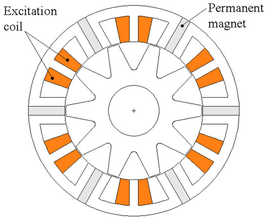
Figure 2.
E-core hybrid excited flux-switching structure [16].
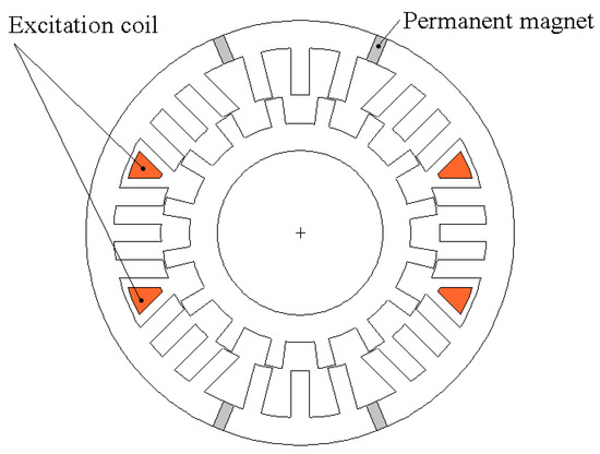
Figure 3.
Doubly salient hybrid excited structure (inner rotor) [46].
Figure 4 shows a new hybrid excited structure where the electromagnetic field sources (permanent magnets, excitation windings and armature windings) are all located in static parts, but armature windings and excitation field sources (permanent magnets and excitation windings) are placed in separate stators. The rotor is completely passive. This structure helps overcome one of the drawbacks of previous flux-switching machines by a better space utilization. Magnetic saturation should appear for higher values of current densities, which should help improve the torque density [19,47].
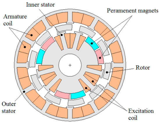
Figure 4.
Separate stators hybrid excitation machine.
Figure 5 shows a hybrid excitation structure recently studied in [37]. Excitation coils are located in the stator avoiding the sliding contacts. Permanent magnets are present in both the stator and rotor armatures. All magnets are polarized in the same direction. Another original hybrid excited structure is presented in Figure 6. In this structure, the hybrid excitation principle is used within an electrical variable transmission. More details about the operation of this machine could be found in reference [32,33]. The structure shown in Figure 7 has been investigated in [6]. In this topology and that of Figure 3, the field created by magnets is in series with the dc excitation field. This limits the flux-adjusting capability because of the low-permeability of magnets. The location of excitation coils in the moving part will be an additional drawback. Other 2D structures have also been studied in [48,49,50,51]. Interested readers may consult these references. All structures presented previously are structures in which magnetic fluxes have a 2D nature. Even if 3D structures are relatively more difficult to analyze and manufacture than 2D ones, research on hybrid excitation machines having 3D structures is still relatively important. Figure 8a shows a hybrid excitation structure that can be considered as the combination of two synchronous structures, a classical permanent magnet structure in the middle and two homopolar inductor structures at both ends [52]. The basic operating principle of this kind of hybrid excitation structure has been previously described in [48].
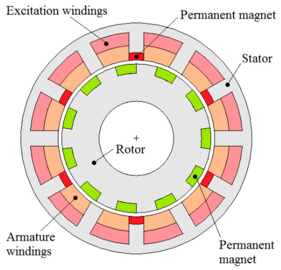
Figure 5.
Hybrid excited dual-permanent-magnet (PM) machine [37].
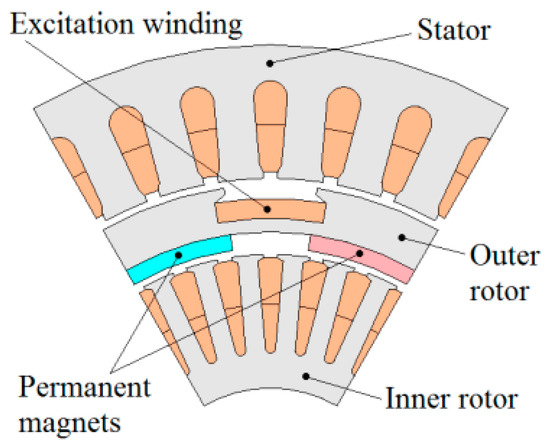
Figure 6.
Electrical variable transmission with hybrid excitation [32,33].
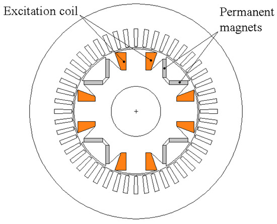
Figure 7.
Series hybrid excited structure [6].
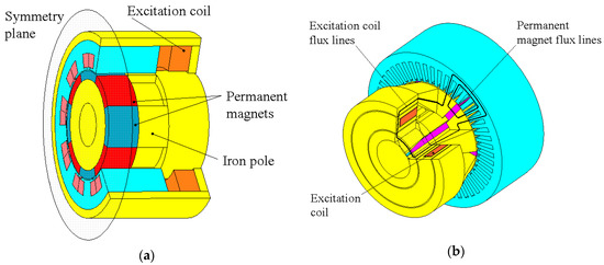
Figure 8.
3D parallel hybrid excited structures. (a) 3D juxtaposed structure [52]; (b) 3D imbricated structure [49,50].
Many 3D hybrid excited structures based on this principle have been recently studied [12,13,36,38,51,53]. Figure 8b illustrates another 3D hybrid excitation structure [10,34,49,54,55]. To a certain extent the basic operating principle of this structure is similar to that of the structure described in [1]. For the structure of Figure 8b, excitation coils are deported to a static part located at an axial end of the machine. This static part could be surrounded by the rotor’s flux collectors (radial auxiliary air-gaps) [10,34,49,54], or in front of these flux collectors (axial auxiliary air-gaps) [55]. The advantage of deporting the excitation windings to this location is the reduction of copper volume and as a consequence the excitation Joule loss and the total machine volume and weight. However, an increase of the machine’s axial length can be feared, and the adopted solution implies the presence of additional air-gaps in the flux path of dc excitation. It should be noted that many hybrid excitation structures have been reported in patent applications [48,56,57,58,59,60,61,62,63,64,65,66,67,68,69,70,71,72,73,74,75]. While the first applications were from European countries, Japan and USA, there is a significant increase of patent applications from China [57,58,59,67,68,69,70,71,72,73,74,75].
3. State of the Art of MEC Modeling
The magnetic equivalent circuits (MECs) modeling approach has been introduced in the late nineteen-sixties [76,77] and early nineteen-seventies [78]. More lately, the MEC modeling started to regain popularity among machine designers but MEC methods lack the genericity when compared to FEA. From the commercial software side, the MEC software is far less widespread than the FEA software. Two types of MEC approaches are mainly employed: Expert reluctance network (also called in literature lumped parameter MEC models) on one side and mesh-based reluctance network (MbRN) on the other side. Lumped parameter models are specifically developed for a dedicated topology and are based on the expertise of the designer. These models often need a prior knowledge of flux paths in the studied topology as shown in the works of Liu et al. [79] and Tang et al. [80]. On the other side, MbRN as a more generic approach is based on the space discretization of the studied domain with multi-directional reluctance block elements. Bidirectional blocks are used in 2D models [81,82] and axial reluctance branches are added to complete the third direction in 3D models [83,84]. Figure 9 shows an example of 2D and 3D reluctance elements.
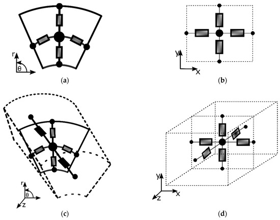
Figure 9.
2D and 3D reluctance block elements. (a) Rectangular bidirectional reluctances; (b) cylindrical bidirectional reluctances; (c) parallelepiped 3D reluctance block element; (d) cylindrical tridimensional reluctance block element.
MECs are also often used in hybrid modeling techniques combining either the analytical formulation, FEA or boundary element method. To model flux-switching machines, the analytical formal solution has been used in combination with MbRN by Laoubi et al. [85] and with lumped parameter MEC by Ilhan et al. in [86]. In [87], Pluk et al. have used 3D MbRN combined with 3D Fourier modeling to model a linear and planar actuator. The boundary element method combined with MEC has been used by Martins Araujo et al. in [88] to model a linear actuator. The FEA-MEC combination has been applied to model a permanent magnet machine by Philips in [89]. Regardless, a little number of computer-aided design (CAD) software exploiting RN modeling has appeared. In this section also, existing tools based on RN modeling are overviewed. On the academic side and in literature, we can mention Turbo-TCM [90] dedicated to small-power turbo-alternator modeling. On the commercial software side, RMxprt® in the ANSYS® Electromagnetic package [91] includes pre-defined designs of stator and rotor topologies that can be combined into one whole machine model for performance assessment but very few information on its working principle are available. SPEED [92] developed by Speed Laboratories (University of Glasgow), uses various analytical formulations as complementary to FEA but again with pre-defined geometries. In another approach, Reluctool® developed by G2ELab (Grenoble, France) is based on lumped parameter MEC for the modeling of electromagnetic devices and includes an optimization module for pre-design purposes [93,94]. Reluctool® models are intimately linked to a given topology, and the reluctance network needs to be built based on the expertise of the designer. All the previously mentioned software come with a graphical interface that allows interactions with the user/designer but none of them allows the automated processing of an arbitrary geometry. On this aspect, for a given structure, a dedicated MEC model needs to be developed. This makes model development duration longer for MEC methods as compared to FEA. Furthermore, if geometry parameters vary in a large scale, the model will no longer be valid and will have to be readjusted. The MEC modeling approach proposed in this study can be referred to as MbRN. It has been developed by many researchers [23,24,77,83,95,96]. The goal of this approach, as indicated earlier, is to overcome the genericity limitation of the classical MEC approach. Developing an analysis and design tool, which can compete with the finite element method in term of precision/computing time ratio, motivated researchers that have studied this technique. Even with a more generic technique, most works using the MEC modeling method have been dedicated to specific topologies as induction machines by Perho [25] or more recently, PM flux-switching machine by Benhamida et al. [97]. The 3D MEC modeling has been used to model a homopolar hybrid excitation synchronous machine with distributed windings and interiors permanent magnets in [98] and lumped parameter MEC for flux concentrating hybrid excitation machine in [99]. This technique consists of meshing the studied object, areas or volumes, using 2D or 3D reluctance block elements, respectively (see Figure 9) [24,82,84,100,101]. The FEM and meshed-based MEC methods share some common meshing rules, i.e., some areas of the studied object have to be more finely meshed than others (air-gap in electric machines). Different aspects related to the mesh-based generated MEC method could be found in [23,24,25,26,82,84,102,103]. A comprehensive review of 3D MEC modeling can be found in [84]. More details on the mesh-based reluctance network model of the hybrid excitation machine studied in this paper will be given in Section 4.2.
4. Hybrid Excitation Topology
Figure 10 shows a 3D cut view of the studied machine. It combines a wound field excitation with a permanent magnet’s excitation. To avoid sliding contacts, excitation windings are located on top of armature end-windings in the stator part of the machine. The basic operating principles of this topology is similar to a structure studied in [50]. Nevertheless, there are a few differences between both topologies. These differences will be highlighted in Section 4.1.
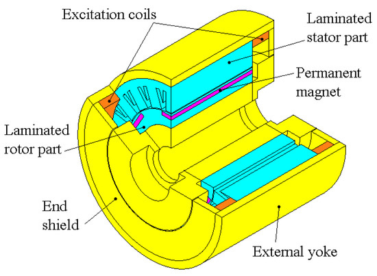
Figure 10.
3D cut view of the hybrid excitation machine.
4.1. Configuration and Operating Principle
The stator of the studied machine is composed of a laminated core, solid iron yoke and end-shields, AC three-phase windings, with concentrated coils, and two excitation annular coils. Solid iron components (external yoke and end-shields) provide a low reluctance path for wound field excitation flux. The rotor is, amongst other things, composed of two solid iron collectors located at both axial ends. Between the two rotoric flux collectors, a solid iron cylinder, located in the axial active length, is connected to both of them. A laminated cylinder in which six permanent magnets are embedded surrounds this massive cylinder. The six permanent magnets create the same type of magnetic poles, either North or South. Between two magnets, there is a laminated iron pole. As for solid iron parts of the stator, the two rotoric flux collectors and the massive cylinder offer a low reluctance path for wound field excitation flux. As for the machine studied in this paper, the structure presented in [50] have two annular excitation coils located in the stator (Figure 11). The machine studied in this paper is illustrated in Figure 11a. Annular excitation coils are placed above the armature end-windings. Another disadvantage affecting the efficiency of flux control using excitation windings is the flux cross-section that is located at the air-gaps between inner radii of end-shields and rotoric flux collectors. The flux cross-section will be further reduced when the annular excitation windings are placed under the armature end-windings. This matter is illustrated in Figure 11b where Rmin is the radius corresponding to the smaller wound field flux cross-section.

Figure 11.
Annular excitation coils location. (a) Above armature end-windings; (b) below armature end-windings.
This implies that magnetic saturation may affect wound field excitation for lower values of excitation current and consequently reduce the flux control capability. Furthermore, while in [50], authors used soft magnetic composite (SMC) material to provide a low reluctance path for wound field excitation flux; massive iron is used in the machine studied in this paper. In addition, the machine presented in [50] is completely enclosed. This constitutes a drawback from the thermal point of view. Figure 12 shows principal flux trajectories of PM excitation flux. Flux trajectories can be divided into two categories: Bipolar flux lines and homopolar flux lines. The presence of a homopolar flux trajectory implies the presence of a DC component in armature flux linkage. Figure 12 also shows wound field excitation flux trajectories. Both annular excitation coils create a magnetic flux having a homopolar trajectory. They both create the same kind of magnetic poles, either North or South, depending on the circulation direction of excitation current in the excitation coils. Since the permanent magnets relative permeability is close to that of air, the flux created by the excitation coils will mainly circulate through the laminated iron pole located between the magnets. The excitation flux control is achieved by acting on the peak-to-peak amplitude of excitation flux using the excitation coils. If the excitation coils create magnetic poles with a reverse polarity as compared to magnets poles, the peak-to-peak amplitude of excitation flux linkage will be enhanced. Otherwise, the peak-to-peak value will be weakened.
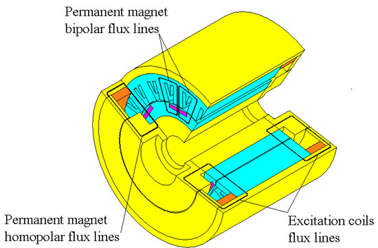
Figure 12.
Main magnetic flux paths of the hybrid excitation machine.
4.2. Prototype Construction
In order to verify the operating principle and to assess the flux control capability of the proposed field sources combination, a prototype has been designed and constructed. The prototype has been designed via a parametric study, by use of the finite element method. The initial design parameters of this machine have been derived from a simple analytical model based on a simple reluctance network. For the double excitation circuit’s design, the principle of equalization of flux cross-sections has been used [5]. The design constraints to be satisfied are given in Table 1. Figure 13a,b shows respectively, longitudinal cut view, and stator and rotor laminations of designed machine with main geometric dimensions. Values of these parameters are given in Table 2. Instead of being perfect cylinders, massive rotoric parts, are hollow cylinders with conical shapes in order to reduce rotor inertia.

Table 1.
Design constraints.
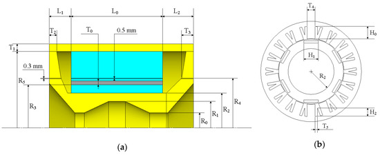
Figure 13.
Main design dimensions. (a) Longitudinal cut view; (b) stator and rotor laminations.
Table 2.
Machine main geometric dimensions.
The end-shields thickness at inner radius is greater than its thickness at outer radius, as can be seen in Figure 13a. It should be noted that air-gap thickness in the machine’s active part (0.5 mm) is slightly greater than the air-gap thickness between end-shields and rotoric flux collectors at both axial ends (0.3 mm). The number of armature windings turns is equal to three. The length between the stator laminated stack axial end, at one side, and the machine axial end, at the same side, is greater at one side as compared to the other side (L2 > L1). Figure 13b shows the stator and rotor lamination sheets (M270-35A). Massive parts are made of solid iron XC18 (see Table 3).
Table 3.
Double excitation synchronous machine data.
Armature windings are constituted by connecting non-overlapping concentrated windings realised using rectangular section wires (see Figure 14). The triangular shape of lamination in each stator slot helps improve the heat transfer. The use of this kind of wire helps to improve the stacking factor and reduce armature end-windings volume. As can be seen from Figure 14, the armature end-windings volume is quite small. However, additional AC Joule loss can be feared due to the large wire section. Nevertheless, stranding armature windings conductors can reduce these losses. Figure 15 shows respectively the rotor and the machine during assembling.
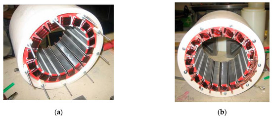
Figure 14.
Stator’s active part assembling. (a) Front view; (b) back view.

Figure 15.
Machine during assembling. (a) Rotor assembling; (b) machine assembling.
5. Modeling of the Hybrid Excitation Synchronous Machine
Electric machines models are established for analysis and design purposes. Two methods are used, in this study, for the modeling of the double excitation machine: Finite element method (FEM), and magnetic equivalent circuits method (MEC). The finite element method, which is a numerical analysis method, is time consuming, in particular for 3D problems and especially at first design stages. This is why the MEC method, which is a semi-analytical method, is also used. The MEC method presents a good compromise between accuracy and computation time. However, the MEC method is not as generic as the finite element method. To overcome this, an improved and more generic MEC modeling approach is used [23,24,25,26,84]. The modeling study using the two methods is presented in this section.
5.1. 3D Finite Element Method
The structure of the studied machine requires the use of the 3D finite element multi-static analysis. Figure 16 shows the 3D finite element mesh of the studied machine (133,958 nodes). The non-linearity of B-H curves of the different parts of the machine is considered.
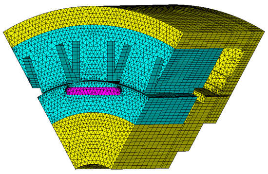
Figure 16.
3D finite element mesh.
The laminated parts are modeled using anisotropic material characteristics. Due to symmetry consideration, only 1/6 of the machine is modeled (one unique pole pair is considered). The magnetic scalar potential formulation is used. The mesh of only 1/12 of the machine is shown to highlight the smoothness of the mesh.
The finite element calculations are done considering two air volumes at axial ends of the machine [5]. The Dirichlet boundary condition is applied to the bounding surface in both axial limits of the finite element model and for Rext (the machine’s external radius). The developed model takes into account the rotor motion.
The air-gap is divided into two parts; a part is linked to the rotor and the other part to the stator. Motion consideration has already been described in [5]. The lamination effect is considered in the finite element calculations via an anisotropic material property for laminated parts. Computation of relative permeability in the perpendicular direction to the lamination is described in [5,104].
The FEA is used for the analysis of flux control capability of the double excitation machine. To do so, flux variation with the rotor position is first calculated for different values of excitation current. The flux linkage in the three phases is calculated by getting flux density distributions in the three teeth. The EMF is obtained by differentiating the flux linkage.
5.2. Magnetic Equivalent Circuit Model
The used MEC modeling technique applied to the HESM consists of meshing the studied object, areas or volumes, using 2D or 3D reluctance elements, respectively. The elementary reluctance blocks used for 2D and 3D problems, concur to the geometries of flux tubes that appear most often in electromagnetic devices [82,86,102,105].
5.2.1. Mesh Generation Algorithm and Modeling of Motion
Figure 17a shows a parallelepiped flux path region and its corresponding passive 2D element. The values of permeances Pv and Pw are given by Equation (1) where l and h are respectively the element dimensions in the v and w directions. Accordingly, Figure 17b shows a cylindrical bidirectional reluctance flux path region also for a passive 2D element. The values of permeances Pr1 and Pr2 in the radial direction and permeance Pθ in the θ directions are given by Equation (2) where r1, r2 and r3 are respectively the lower, the mid and the higher radius delimiting the reluctance block element and Δθ its opening angle.
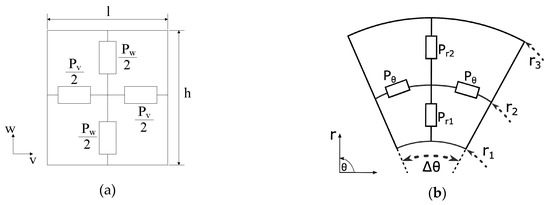
Figure 17.
Flux paths regions and corresponding 2D elementary reluctance block elements. (a) Parallelepiped bidirectional reluctance block element; (b) cylindrical bidirectional reluctance block element.
Figure 18a,b show some elements used for the mesh of the studied machine. Figure 18c shows the different components contained in each branch of those elements. For a completely passive element, the MMF sources Fsei = 0 A and the flux sources Φsei = 0 Wb (i = 1, 2, 3, 4, 5, 6 in Figure 18a), or (i = 1, 2, 3, 4, 5 in Figure 18b). Figure 19 illustrates how the value of relative permeability in z direction (axial direction) is estimated for laminated machine parts. Laminated parts are considered as a succession of ferromagnetic and non-magnetic (lamination insulation and parasitic air-gaps) materials. A packing factor kf, defined as the total length of ferromagnetic steel parts divided by total laminated pack length (active length), is set to 97%. Equation (3) gives then the value of the equivalent relative permeability in axial direction. μr is the relative permeability of ferromagnetic parts.
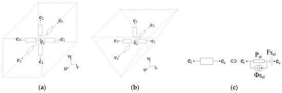
Figure 18.
3D elementary reluctance blocks. (a) 7-node block element; (b) 6-node block element; (c) branch components.
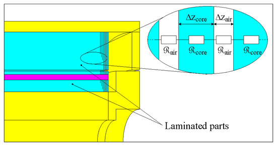
Figure 19.
Lamination effect modeling.
As for the finite element computations, two air volumes at axial ends of the machine are considered in the MEC model. The lamination effect is also taken into account in the same way as the finite element model. The nodal method is used to formulate the MEC equations system. The unknowns for the generated circuit equations system are the magnetic scalar potentials at each node. The equations system referred to in Equation (4) is solved using the MATLAB software. For that purpose, it is expressed using the matrix formulation where, [P] is the permeance matrix, [U] is the magnetic scalar potential vector, [Φ] is the flux source vector and n is the total number of nodes. For each moving armature/stator relative position a new equations system is established. It should be noticed that only the air-gap region has to be remeshed for each position, and that the reluctances connecting the nodes located at the stator/air-gap and moving armature/air-gap interfaces have to be recalculated.
Figure 20 summarizes the mesh-based generated MEC method incorporating magnetic saturation consideration and motion. The first step is to mesh the different regions of the studied object. Then, comes the node numbering before calculating the matrices [P] and [Φ]. After the solving of the algebraic system, the permeances of the block elements modeling the ferromagnetic parts are recalculated by adapting their permeabilities via the iterative process till convergence towards a magnetic equilibrium state.

Figure 20.
Mesh-based generated MEC method algorithm.
5.2.2. Modeling of Magnetic Field Sources
The modeling of permanent magnets and electric coils is discussed in this section. Permanent magnets can either be modeled by a flux source in parallel with a permeance or a magneto-motive force (MMF) in series with a permeance, as shown in Figure 21. Expressions of the different parameters of a permanent magnet region model depend on PM characteristics and the region geometry and dimensions. These expressions for a parallelogram PM region are given by Equation (5) where, Br and μr are, respectively, the magnetic remanence and the relative permeability of the permanent magnet. lpm, hpm and wpm are, respectively, PM length, height and width. Φpm and Fpm are PM flux source and PM MMF source.
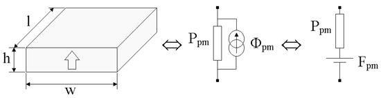
Figure 21.
Permanent magnet region modeling.
There are two types of electric coils in double excitation machines: Armature windings and wound field excitation coils. Armature windings are often distributed in slots and can be divided into two parts: Conductors contained in the slot volumes and armature end-windings. Figure 22a shows the MMF variation with w coordinate for the coil and the maximum MMF value is equal to the product of the number of turns and current in one conductor (, where Nt is the number of turns and I the value of armature current in one conductor in the slot). Values of MMF sources for the different elements, es1, es2, es3 and ey1, depend on the geometric dimensions of these elements and the value of armature current in the slot as illustrated in Figure 22b,c. Expressions of MMF sources in these elements are given by Equation (6).

Figure 22.
Magneto-motive force (MMF) coil variation.
The same technique is used for modeling the end-windings part of the armature coil and for both annular excitation coils (see Figure 23). MMF will vary accordingly with the variation of current at each motion step.

Figure 23.
Armature end-windings modeling.
5.2.3. Air-Gap Modeling
In order to model the air-gap, two types of reluctance elements can be used: Unidirectional (radial direction for radial flux rotating machines) or multi-directional reluctance blocks (see Figure 9 and Figure 17). This depends on the global quantity which is sought (flux or torque), the calculation time constraint and the sought precision [25,82]. For the study of flux control capability the use of unidirectional reluctances is largely enough. Furthermore, the use of unidirectional reluctances implies a reduced number of nodes, as compared to multi-directional reluctances, and as a consequence a reduced calculation time.
Figure 24 illustrates, on a simple 2D case, how the value of the reluctance between a static element and a moving element is calculated as a function of the moving armature relative position. For clarity reasons, only one static element e1 from the stator and one moving element e2 from the moving armature are represented (Figure 24a). The value of the unidirectional permeance between the two elements (see Figure 24b) is given by Equation (7) where, lag is the air-gap length, La is the elements axial length (it is supposed to be the same for both elements in 3D problems), and Δv is given by Equation (8). α and β values are given by Equation (9).
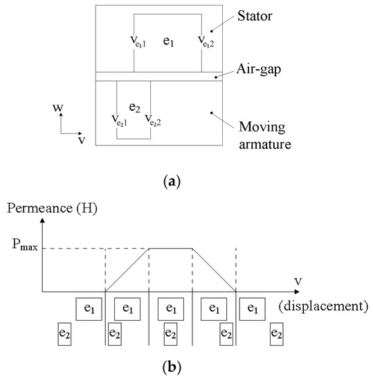
Figure 24.
Air-gap permeance (reluctance) calculation.
5.2.4. Equations System Solution and Magnetic Saturation
Figure 25 illustrates how elements of the matrix [P] and [Φ] are determined from Kirchhoff’s laws. According to Kirchhoff’s laws, it can be established that the sum of fluxes going into each node is null and the magnetic potential difference of two nodes is equal to the flux of the branch linking both nodes divided by the permeance of the same branch as shown in Equations (10) and (11), respectively. Elements of matrix [P] and [Φ] can be directly determined from Equation (11). For the nodes that are not directly connected to the ith node, the values of Pij, Fmsij and Φsij are null.
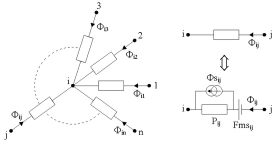
Figure 25.
Mesh equation setting for the ith node.
In order to take into account the magnetic saturation, the equations system is solved iteratively by adjusting the value of the permeance matrix [P] elements at each iteration. The convergence criterion is given by Equation (12) where μek and μek+1 correspond to the value of relative permeability in the reluctance element e respectively at the kth and (kth + 1) iteration of the iterative process described earlier (see Figure 20).
The open-circuit flux in a phase is estimated, for each position, by averaging radial flux passing through the tooth region covered by the concentrated winding (Figure 26). The average flux passing through the concentrated winding is calculated using elements et9 to et14, which are the elements belonging to the tooth region covered by the concentrated winding in Figure 26a. Previous to describing how the open-circuit flux linkage is calculated, the radial flux passing through an element should be defined (Figure 26b); it is given by Equation (13). The flux passing through the concentrated winding is then calculated as follows:
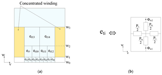
Figure 26.
Open-circuit radial flux linkage calculation.
- The radial flux (w direction in 0) passing through the layer containing elements et9 to et12 is first calculated as shown by Equation (14);
- Then, the radial flux passing through the second layer containing elements et13 and et14 is calculated as shown by Equation (15);
- Finally, the average flux linkage, per turn, passing through the concentrated winding is given by Equation (16).
The electromotive force is calculated by the flux derivative as can be shown by Equation (17). The hybrid torque is calculated as can be shown by Equation (18). Torque estimation can also be based either on the variation of magnetic energy [98] or is evaluated via the maxwell stress tensor (MST) method. In order to calculate the torque based on the MST method [82,98,106], access is needed to both normal and tangential components of air-gap flux density. Since the air-gap is modeled using unidirectional reluctances, the use of MST is not possible. However, it is possible to estimate the hybrid component of the torque of the machine [107,108]. The product of current gives the hybrid torque estimation and EMF as shown by Equation (18) where T is the hybrid torque, Nt is the number of turns of armature windings, Ω is the rotational speed, and I is the phase current. The number of nodes for the 3D mesh-based generated MEC model, of the hybrid excitation machine, is equal to 8680. This is fifteen times lower than the number of nodes in the 3D finite element model. Since unidirectional reluctances are used for the modeling of the air-gap, the number of nodes is kept constant for all rotor/stator relative positions.
6. Experimental Validation, Comparison and Discussion
In this section, results from both modeling methods: The finite element model (FEM) and the magnetic equivalent circuit model (MEC), are compared to each other and to experimental measurements.
Figure 27 compares the measured open-circuit line-to-line electromotive force (EMF) per-turn waveform for a null value of excitation current (Iexc = 0 A) to corresponding waveforms obtained from the FEM and the MEC model. Figure 28a,b shows the same comparison, i.e., open-circuit line-to-line EMF per-turn for Iexc = −4 A and Iexc = 4 A, respectively. As can be seen, a fairly good agreement is achieved between measurements and both modeling methods. Measurements are done for a rotational speed of 170 rpm. It should be noticed that the computation time for the MEC and FEM methods are respectively 4.7 s and 1560 s for one position; computations being done with the same computer. Figure 29 compares the measured RMS value line-to-line flux linkage variations with excitation current to corresponding variations obtained from the 3D FEM and the MEC model. The measured RMS values of line-to-line flux linkage are obtained by first integrating line-to-line EMF waveforms and then calculating the RMS value.
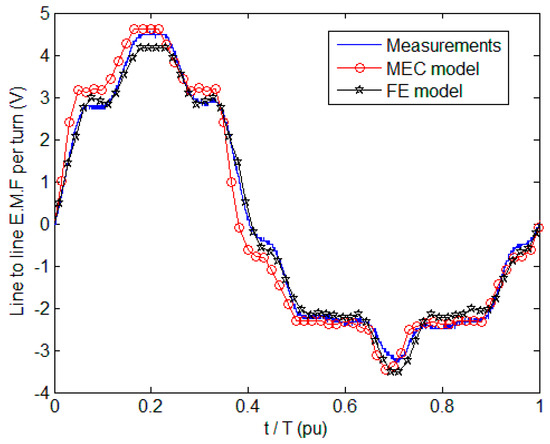
Figure 27.
Open-circuit line-to-line EMF per-turn for Iexc = 0 A.
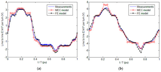
Figure 28.
Open-circuit line-to-line EMF per-turn. (a) For Iexc = − 4 A; (b) for Iexc = + 4 A.

Figure 29.
Open-circuit line-to-line maximum flux linkage variations with Iexc.
From Figure 29, it can be seen that a wide range of air-gap flux control can be achieved. The air-gap flux changes with a variation of +57% when air-gap flux is enhanced and −35% when it is weakened, with respect to the no-field excitation flux (Iexc = 0 A). Numerous reasons can explain the models discrepancies on global quantities such as flux and back-EMF. First, the mesh (spatial discretization) is not the same on both models. Another difference is that the 3D-FEA model is developed on a commercial FEA software and the implemented numerical methods (i.e., derivatives calculations, non-linear behaviors considerations) are not the same as those of the 3D-MEC model developed in MATLAB (see Figure 20).
Figure 30 compares the developed maximum hybrid torque evaluated by the FEA and MEC models with an armature current density of Jmax= 10 A/mm² at a rotational speed of 170 rpm for Iexc = −4 A, Iexc = 0 A and Iexc = +4 A, respectively. It can be seen from Figure 30 that magnetic saturation effects induce an increased error between models. The best agreement between both modeling techniques is obtained at Iexc = −4 A when the air-gap flux is weakened and magnetic saturation is low. When air-gap flux is enhanced (Iexc = +4 A) the difference between the MEC and FEA models is the greatest.
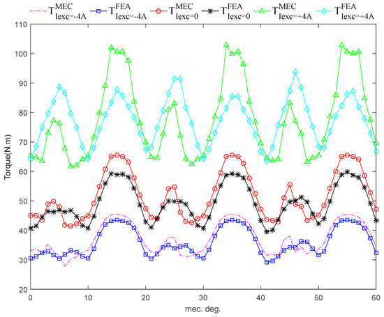
Figure 30.
Torque vs. rotor position (MEC and FEA comparison) (170 rpm, Jmax = 10 A/mm²).
7. Conclusions
This paper allowed presenting a double excitation machine and studying its field weakening capability. A prototype has been built and delivered to a car manufacturer. The excitation flux control characteristic has been studied experimentally before delivering the prototype. This study has shown the relatively good flux control capability of the prototype. The machine has been modeled using two different modeling methods: The FEA method and mesh-based generated MEC method. The two modeling methods are complementary for a design optimization process. As it has been shown in Section 6 the mesh-based generated MEC model was fairly accurate when compared to the FEM method while necessitating less time. Computation time for the MEC and FEM methods were respectively 4.7 s and 1560 s for one position (computations done with the same computer were divided by ≈ 330). Its genericity and time saving, makes it well adapted for optimal design studies in the pre-design stage of electromagnetic devices. These features are even more noticeable in the case of complicated 3D structures as the hybrid excitation structure studied in this paper.
Author Contributions
The work presented here was a cooperative effort by all the authors.
Funding
This research received no external funding.
Acknowledgments
This work was supported in part by “Le Groupement de Recherche Systèmes d’Energie Electrique dans leur Dimension Sociétale” (GdR SEEDS). This scientific study is related to the project Groupe de Travail (GT) "Modèles analytiques". The authors would like to thank GdR SEEDS (France) for the help they provided in this work and on this project.
Conflicts of Interest
The authors declare no conflict of interest.
References
- Amara, Y.; Vido, L.; Gabsi, M.; Hoang, E.; Ben Ahmed, A.H.; Lecrivain, M. Hybrid Excitation Synchronous Machines: Energy-Efficient Solution for Vehicle Propulsion. IEEE Trans. Veh. Technol. 2009, 58, 2137–2149. [Google Scholar] [CrossRef]
- Finken, T.; Hameyer, K. Study of hybrid excited synchronous alternators for automotive applications using coupled FE and circuit simulations. IEEE Trans. Magn. 2008, 44, 1598–1601. [Google Scholar] [CrossRef]
- Al-Adsani, A.S.; Schofield, N. Hybrid permanent magnet generators for electric vehicle applications. In Proceedings of the 2009 IEEE International Electric Machines and Drives Conference, Miami, FL, USA, 3–6 May 2009; pp. 1754–1761. [Google Scholar] [CrossRef]
- Zhao, C.; Yan, Y. A review of development of hybrid excitation synchronous machine. In Proceedings of the IEEE International Symposium on Industrial Electronics 2005, Dubrovnik, Croatia, 20–23 June 2005. [Google Scholar] [CrossRef]
- Nedjar, B.; Hlioui, S.; Amara, Y.; Vido, L.; Gabsi, M.; Lécrivain, M. A new parallel double excitation synchronous machine. IEEE Trans. Magn. 2011, 47, 2252–2260. [Google Scholar] [CrossRef]
- Kamiev, K.; Nerg, J.; Pyrhönen, J.; Zaboin, V.; Hrabovcova, V.; Rafajdus, P. Hybrid excitation synchronous generators for island operation. LET Electr. Power Appl. 2012, 6, 1–11. [Google Scholar] [CrossRef]
- Wang, Y.; Deng, Z. Hybrid excitation topologies and control strategies of stator permanent magnet machines for DC power system. IEEE Trans. Ind. Electron. 2012, 59, 4601–4616. [Google Scholar] [CrossRef]
- Yang, H.; Zhu, Z.Q.; Chu, W. Flux adjustable permanent magnet machines: A technology status review. Chin. J. Electr. Eng. 2016, 2, 14–30. [Google Scholar] [CrossRef]
- Wang, Q.; Niu, S. Overview of flux-controllable machines: Electrically excited machines, hybrid excited machines and memory machines. Renew. Sustain. Energy Rev. 2017, 68, 475–491. [Google Scholar] [CrossRef]
- Zhang, Z.; Dai, J.; Dai, C.; Yan, Y. Design considerations of a hybrid excitation synchronous machine with magnetic shunt rotor. IEEE Trans. Magn. 2013, 49, 5566–5573. [Google Scholar] [CrossRef]
- Chen, Z.; Wang, B.; Chen, Z.; Yan, Y. Comparison of Flux Regulation Ability of the Hybrid Excitation Doubly Salient Machines. IEEE Trans. Ind. Electron. 2014, 61, 3155–3166. [Google Scholar] [CrossRef]
- Geng, W.; Zhang, Z.; Member, S.; Jiang, K.; Yan, Y. A New Parallel Hybrid Excitation Machine: Machine with Bidirectional Field-Regulating Capability. IEEE Trans. Ind. Electron. 2015, 62, 1372–1381. [Google Scholar] [CrossRef]
- Wang, H.; Qu, Z.; Tang, S.; Pang, M.; Zhang, M. Analysis and optimization of hybrid excitation permanent magnet synchronous generator for stand-alone power system. J. Magn. Magn. Mater. 2017, 436, 117–125. [Google Scholar] [CrossRef]
- Tapia, J.A.; Leonardi, F.; Lipo, T.A. Consequent-pole permanent-magnet machine with extended field-weakening capability. IEEE Trans. Ind. Appl. 2003, 39, 1704–1709. [Google Scholar] [CrossRef]
- Kosaka, T.; Sridharbabu, M.; Yamamoto, M.; Matsui, N. Design studies on hybrid excitation motor for main spindle drive in machine tools. IEEE Trans. Ind. Electron. 2010, 57, 3807–3813. [Google Scholar] [CrossRef]
- Chen, J.T.; Zhu, Z.Q.; Iwasaki, S.; Deodhar, R.P. A novel hybrid-excited switched-flux brushless AC machine for EV/HEV applications. IEEE Trans. Veh. Technol. 2011, 60, 1365–1373. [Google Scholar] [CrossRef]
- Kamiev, K.; Pyrhonen, J.; Nerg, J.; Zaboin, V.; Tapia, J. Modeling and Testing of an Armature-Reaction-Compensated (PM) Synchronous Generator. IEEE Trans. Energy Convers. 2013, 28, 849–859. [Google Scholar] [CrossRef]
- Giulii Capponi, F.; De Donato, G.; Borocci, G.; Caricchi, F. Axial-flux hybrid-excitation synchronous machine: Analysis, design, and experimental evaluation. IEEE Trans. Ind. Appl. 2014, 50, 3173–3184. [Google Scholar] [CrossRef]
- Hua, H.; Zhu, Z.Q. Novel Parallel Hybrid Excited Machines with Separate Stators. IEEE Trans. Energy Convers. 2016, 31, 1212–1220. [Google Scholar] [CrossRef]
- Bash, M.L.; Pekarek, S.D. Modeling of salient-pole wound-rotor synchronous machines for population-based design. IEEE Trans. Energy Convers. 2011, 26, 381–392. [Google Scholar] [CrossRef]
- Bash, M.L.; Pekarek, S. Analysis and validation of a population-based design of a wound-rotor synchronous machine. IEEE Trans. Energy Convers. 2012, 27, 603–614. [Google Scholar] [CrossRef]
- Sudhoff, S.D.; Shane, G.M.; Suryanarayana, H. Magnetic-equivalent-circuit-based scaling laws for low-frequency magnetic devices. IEEE Trans. Energy Convers. 2013, 28, 746–755. [Google Scholar] [CrossRef]
- Rasmussen, C.B.; Ritchie, E. A magnetic equivalent circuit approach for predicting PM motor performance. In Proceedings of the IAS’97 Conference Record of the 1997 IEEE Industry Applications Conference Thirty-Second IAS Annual Meeting, New Orleans, LA, USA, 5–9 October 1997. [Google Scholar] [CrossRef]
- Demenko, A.; Lech, N.; Szelag, W. Reluctance Network Formed by Means of Edge Element Method. IEEE Trans. Magn. 1998, 34, 2485–2488. [Google Scholar] [CrossRef]
- Perho, J. Reluctance Network for Analysing Induction Machines; Helsinki University of Technology: Espoo, Finland, 2002. [Google Scholar]
- Amrhein, M.; Krein, P.T. Induction machine modeling approach based on 3-D magnetic equivalent circuit framework. IEEE Trans. Energy Convers. 2010, 25, 339–347. [Google Scholar] [CrossRef]
- Kou, B.; Jin, Y.; Zhang, H.; Zhang, L.; Zhang, H. Analysis and design of hybrid excitation linear eddy current brake. IEEE Trans. Energy Convers. 2014, 29, 496–506. [Google Scholar] [CrossRef]
- Li, W.; Ching, T.W.; Chau, K.T. Design and analysis of a new parallel-hybrid-excited linear vernier machine for oceanic wave power generation. Appl. Energy 2017, 208, 878–888. [Google Scholar] [CrossRef]
- Hsu, J.S. Direct control of air-gap flux in permanent-magnet machines. IEEE Trans. Energy Convers. 2000, 15, 361–365. [Google Scholar] [CrossRef]
- Yildiriz, E.; Gulec, M.; Aydin, M. An Innovative Dual-Rotor Axial-Gap Flux-Switching Permanent-Magnet Machine Topology with Hybrid Excitation. IEEE Trans. Magn. 2018. [Google Scholar] [CrossRef]
- Nasr, A.; Hlioui, S.; Gabsi, M.; Mairie, M.; Lalevee, D. Design Optimization of a Hybrid-Excited Flux-Switching Machine for Aircraft safe DC Power Generation using a Diode Bridge Rectifier. IEEE Trans. Ind. Electron. 2017, 64, 9896–9904. [Google Scholar] [CrossRef]
- Druant, J.; Vansompel, H.; De Belie, F.; Sergeant, P. Optimal Control for a Hybrid Excited Dual Mechanical Port Electric Machine. IEEE Trans. Energy Convers. 2017, 32, 599–607. [Google Scholar] [CrossRef]
- Druant, J.; Vansompel, H.; De Belie, F.; Melkebeek, J.; Sergeant, P. Torque Analysis on a Double Rotor Electrical Variable Transmission with Hybrid Excitation. IEEE Trans. Ind. Electron. 2017, 64, 60–68. [Google Scholar] [CrossRef]
- Liu, Y.; Zhang, Z.; Zhang, X. Design and Optimization of Hybrid Excitation Synchronous Machines with Magnetic Shunting Rotor for Electric Vehicle Traction Applications. IEEE Trans. Ind. Appl. 2017. [Google Scholar] [CrossRef]
- Berkoune, K.; Ben Sedrine, E.; Vido, L.; Le Ballois, S. Robust control of hybrid excitation synchronous generator for wind applications. Math. Comput. Simul. 2017, 131, 55–75. [Google Scholar] [CrossRef]
- Wang, Y.; Deng, Z. A Controllable Power Distribution Strategy for Open Winding Hybrid Excitation Generator System. IEEE Trans. Energy Convers. 2017, 32, 122–136. [Google Scholar] [CrossRef]
- Wang, Q.; Niu, S. A Novel Hybrid-Excited Dual-PM Machine with Bidirectional Flux Modulation. IEEE Trans. Energy Convers. 2017, 32, 424–435. [Google Scholar] [CrossRef]
- Beik, O.; Schofield, N. High-Voltage Hybrid Generator and Conversion System for Wind Turbine Applications. IEEE Trans. Ind. Electron. 2018, 65, 3220–3229. [Google Scholar] [CrossRef]
- Mseddi, A.; Le Ballois, S.; Aloui, H.; Vido, L. Robust control of a wind conversion system based on a hybrid excitation synchronous generator: A comparison between H∞ and CRONE controllers. Math. Comput. Simul. 2018. [Google Scholar] [CrossRef]
- Cheraghi, M.; Karimi, M. Optimal design of a Hybrid Excited Doubly Salient Permanent Magnet generator for wind turbine application. In Proceedings of the 2017 8th Power Electronics, Drive Systems & Technologies Conference (PEDSTC), Mashhad, Iran, 14–16 February 2017; pp. 19–24. [Google Scholar] [CrossRef]
- Hoang, E.; Lecrivain, M.; Gabsi, M. A new structure of a switching flux synchronous polyphased machine with hybrid excitation. In Proceedings of the 2007 European Conference on Power Electronics and Applications, Aalborg, Denmark, 2–5 September 2007; pp. 1–8. [Google Scholar] [CrossRef]
- Sulaiman, E.; Kosaka, T.; Matsui, N. Design and analysis of high-power/high-torque density dual excitation switched-flux machine for traction drive in HEVs. Renew. Sustain. Energy Rev. 2014, 34, 517–524. [Google Scholar]
- Owen, R.L.; Zhu, Z.Q.; Jewell, G.W. Hybrid-excited flux-switching permanent-magnet machines with iron flux bridges. IEEE Trans. Magn. 2010, 46, 1726–1729. [Google Scholar] [CrossRef]
- Hua, W.; Cheng, M.; Zhang, G. A novel hybrid excitation flux-switching motor for hybrid vehicles. IEEE Trans. Magn. 2009, 45, 4728–4731. [Google Scholar] [CrossRef]
- Dupas, A.; Hlioui, S.; Hoang, E.; Gabsi, M.; Lecrivain, M. Investigation of a New Topology of Hybrid-Excited Flux-Switching Machine with Static Global Winding: Experiments and Modeling. IEEE Trans. Ind. Appl. 2016, 52, 1413–1421. [Google Scholar] [CrossRef]
- Zhang, Z.; Tao, Y.; Yan, Y. Investigation of a New Topology of Hybrid Excitation Doubly Salient Brushless DC Generator. IEEE Trans. Ind. Electron. 2012, 59, 2550–2556. [Google Scholar] [CrossRef]
- Du, Y.; Lu, W.; Zhu, X.; Quan, L. Optimal Design and Analysis of Partitioned Stator Hybrid Excitation Doubly Salient Machine. IEEE Access 2018, 6, 57700–57707. [Google Scholar] [CrossRef]
- Syverson, D. Hybrid Alternator. U.S. Patent US5397975A, 14 March 1995. [Google Scholar]
- Zhang, Z.; Yan, G.; Yang, S.; Bo, Z. Principle of operation and feature investigation of a new topology of hybrid excitation synchronous machine. IEEE Trans. Magn. 2008, 44, 2174–2180. [Google Scholar] [CrossRef]
- Kosaka, T.; Matsui, N. Hybrid Excitation Machines with Powdered Iron Core for Electrical Traction Drive Applications. In Proceedings of the 2008 International Conference on Electrical Machines and Systems (ICEMS), Wuhan, China, 17–20 October 2008; pp. 2974–2979. [Google Scholar]
- Wang, Y.; Deng, Z.-Q. A Position Sensorless Method for Direct Torque Control with Space Vector Modulation of Hybrid Excitation Flux-Switching Generator. IEEE Trans. Energy Convers. 2012, 27, 912–921. [Google Scholar] [CrossRef]
- Fu, X.; Zou, J. Numerical analysis on the magnetic field of hybrid exciting synchronous generator. IEEE Trans. Magn. 2009, 45, 4590–4593. [Google Scholar] [CrossRef]
- Wu, Y.; Sun, L.; Zhang, Z.; Miao, Z.; Liu, C. Analysis of Torque Characteristics of Parallel Hybrid Excitation Machine Drives with Sinusoidal and Rectangular Current Excitations. IEEE Trans. Magn. 2018, 54, 1–5. [Google Scholar] [CrossRef]
- Shi, M.; Zhou, B.; Wei, J.; Zhang, Z.; Mao, Y.; Han, C. Design and practical implementation of a novel variable-speed generation system. IEEE Trans. Ind. Electron. 2011, 58, 5032–5040. [Google Scholar] [CrossRef]
- Zhang, Z.; Ma, S.; Dai, J.; Yan, Y. Investigation of hybrid excitation synchronous machines with axial auxiliary air-gaps and non-uniform air-gaps. IEEE Trans. Ind. Appl. 2014, 50, 1729–1737. [Google Scholar] [CrossRef]
- Greif, H.; Nguyen, N.-T.; Mueller, A.; Reutlinger, K. Electric Machine with a Rotor with Hybrid Excitation. International Patent WO2011036135A1, 31 March 2011. [Google Scholar]
- Fang, Y.; Liu, Q.; Ma, J.; Meng, L.; Wang, L.; Xia, C.; Yao, Y. Hybrid Excitation Structure. Chinese Patent CN101814821 (A), 25 August 2010. [Google Scholar]
- Xie, S.J.; Xu, Z. Multitooth Magnetic Bridge Type Hybrid Excitation Magnetic Flux Switching Motor. Chinese Patent CN101834474 (A), 15 September 2010. [Google Scholar]
- Xia, G.; Zeng, Q.; Cai, Y. Tangential-Set Magnet Double Salient Hybrid Excitation Motor. Chinese Patent CN201403037 (Y), 10 February 2010. [Google Scholar]
- Akemakou, D. Double-Excitation Rotating Electrical Machine for Adjustable Defluxing. U.S. Patent US20060119206A1, 8 June 2006. [Google Scholar]
- Moynot, V.; Chabot, F.; Lecrivain, M.; Gabsi, M.; Hlioui, S. Rotating Electric Machine with Homopolar Double Excitation. International Patent WO2010052439A2, 14 May 2010. [Google Scholar]
- Wang, G. A Hybrid Excitation Synchronous Generator. International Patent WO2009082875A1, 9 September 2009. [Google Scholar]
- Reutlinger, K. Electric Machine Comprising a Rotor with Hybrid Excitation. International Patent WO2008148621A1, 19 August 2008. [Google Scholar]
- Mizutani, R.; Tatematsu, K.; Yamada, E.; Matsui, N.; Kosaka, T. Rotating Electric Motor. International Patent WO2008093865A1, 7 August 2008. [Google Scholar]
- Hoang, E.; Lecrivain, M.; Gabsi, M. Flux-Switching Dual Excitation Electrical Machine. U.S. Patent US7868506B2, 11 February 2011. [Google Scholar]
- Aydin, M.; Lipo, T.A.; Huang, S. Field Controlled Axial Flux Permanent Magnet Electrical Machine. U.S. Patent US20070046124A1, 1 March 2007. [Google Scholar]
- Yu, H.; Hu, M.; Shi, L.; Qin, F. Hybrid Excitation Linear Synchronous Motor Using Halbach Permanent Magnet. Chinese Patent CN101594040 (A), 2 December 2009. [Google Scholar]
- Wang, H.; Zhao, C.; Guo, H. Hybrid Excitation Brushless Synchronous Motor. Chinese Patent CN101752969 (A), 23 June 2010. [Google Scholar]
- Ahmad, M.Z.; Sulaiman, E.; Haron, Z.A.; Kosaka, T. Impact of Rotor Pole Number on the Characteristics of Outer-rotor Hybrid Excitation Flux Switching Motor for In-wheel Drive EV. Procedia Technol. 2013, 11, 593–601. [Google Scholar] [CrossRef]
- Liu, J.; Yang, X.; Zhang, J.; Xue, J.; Gao, F.; Xiao, C.; Gao, Y.; Tan, F. Hybrid Excitation Motor for New Energy Automobile. Chinese Patent CN108429421 (A), 21 August 2018. [Google Scholar]
- Zhao, J.; Jing, M.; Quan, X.; Sun, X. Direct Predictive Power Control Method for Hybrid Excitation Synchronous Motor. Chinese Patent CN108390602 (A), 10 August 2018. [Google Scholar]
- Diao, T. Alternating-Current and Permanent Magnet Hybrid Excitation Doubly-Fed Wind Power Generator and Power Generation System. Chinese Patent CN108282064 (A), 13 July 2018. [Google Scholar]
- Chao, Z.; Yuefei, Z.U.O.; Feng, L.I.; Zixuan, X. Hybrid Excitation Direct-Drive Motor. Chinese Patent CN108336837 (A), 27 July 2018. [Google Scholar]
- Zhao, J.; Jing, M.; Quan, X.; Sun, X. Non-Salient Pole Type Hybrid Excitation Motor Constant-Power Loss Model Prediction Control Method. Chinese Patent CN108418485 (A), 17 August 2018. [Google Scholar]
- Han, W. Control Method for Electric Vehicle Hybrid Excitation Type Internal Combustion Power Generation Range Extending System. Chinese Patent CN108407624 (A), 17 August 2018. [Google Scholar]
- King, E.I. Equivalent Circuits for Two-Dimensional Magnetic Fields: II—The Sinusoidally Time-Varying Field. IEEE Trans. Power Appar. Syst. 1966, PAS-85, 936–945. [Google Scholar] [CrossRef]
- King, E.I. Equivalent Circuits for Two-Dimensional Magnetic Fields: I—The Static Field. IEEE Trans. Power Appar. Syst. 1966, PAS-85, 927–935. [Google Scholar] [CrossRef]
- Carpenter, C.J. Finite-element network models and their application to eddy-current problems. Proc. Inst. Electr. Eng. 1975, 122, 455–462. [Google Scholar] [CrossRef]
- Liu, G.; Ding, L.; Zhao, W.; Chen, Q.; Jiang, S. Nonlinear Equivalent Magnetic Network of a Linear Permanent Magnet Vernier Machine With End Effect Consideration. IEEE Trans. Magn. 2018, 54, 1–9. [Google Scholar] [CrossRef]
- Tang, Y.; Paulides, J.J.H.; Lomonova, E.A. Analytical Modeling of Flux-Switching In-Wheel Motor Using Variable Magnetic Equivalent Circuits. ISRN Automot. Eng. 2014, 2014, 530260. [Google Scholar] [CrossRef]
- Benlamine, R.; Hamiti, T.; Vangraefschèpe, F.; Dubas, F.; Lhotellier, D. Modeling of a coaxial magnetic gear equipped with surface mounted PMs using nonlinear adaptive magnetic equivalent circuits. In Proceedings of the 2016 XXII International Conference on Electrical Machines (ICEM), Lausanne, Switzerland, 4–7 September 2016; pp. 1888–1894. [Google Scholar] [CrossRef]
- Asfirane, S.; Hlioui, S.; Amara, Y.; Barriere, O.D.L.; Barakat, G.; Gabsi, M. Global Quantities Computation Using Mesh-Based Generated Reluctance Networks. IEEE Trans. Magn. 2018, 54, 1–4. [Google Scholar] [CrossRef]
- Amrhein, M.; Krein, P.T. 3-D magnetic equivalent circuit framework for modeling electromechanical devices. IEEE Trans. Energy Convers. 2009, 24, 397–405. [Google Scholar]
- Benmessaoud, Y.; Dubas, F.; Hilairet, M.; Beniamine, R. Three-dimensional automatic generation magnetic equivalent circuit using mesh-based formulation. In Proceedings of the 2017 20th International Conference on Electrical Machines and Systems (ICEMS), Sydney, Australia, 11–14 August 2017; pp. 1–6. [Google Scholar] [CrossRef]
- Laoubi, Y.; Dhifli, M.; Barakat, G.; Amara, Y. Hybrid analytical modeling of a flux switching permanent magnet machines. In Proceedings of the 2014 International Conference on Electrical Machines (ICEM), Berlin, Germany, 2–5 September 2014; pp. 1018–1023. [Google Scholar] [CrossRef]
- Ilhan, E.E.; Gysen, B.L.J.; Paulides, J.J.H.; Lomonova, E.A. Analytical Hybrid Model for Flux Switching Permanent Magnet Machines. IEEE Trans. Magn. 2010, 46, 1762–1765. [Google Scholar] [CrossRef]
- Pluk, J.W.K.; Jansen, J.W.; Lomonova, E.A. 3-D Hybrid Analytical Modeling: 3-D Fourier Modeling Combined With Mesh-Based 3-D Magnetic Equivalent Circuits. IEEE Trans. Magn. 2015, 51, 1–14. [Google Scholar] [CrossRef]
- Martins, D.; Araujo, C.J.-L.; Delinchant, B.; Chadebec, O. A Hybrid Method BEM-NRM for Magnetostatics Problems. J. Microw. Optoelectron. Electromagn. 2013, 12, 555–568. [Google Scholar]
- Philips, D.A. Coupling Finite Elements and Magnetic Networks in Magnetostatics. Int. J. Numer. Methods Eng. 1992, 35, 1991–2002. [Google Scholar]
- Petrichenko, D. Calculation and Simulation of Turbogenerators Using Permeance Network. Optimization Application. Ph.D. Thesis, École Centrale de Lille, Villeneuve-d’Ascq, France, 2007. [Google Scholar]
- ANSYS®. Electromagnetics Suite, Release 16.2. Available online: https://www.ansys.com/ (accessed on 27 March 2019).
- Miller, T.J.E.; McGilp, M.; Wearing, A. Motor Design Optimisation Using SPEED CAD Software. In Proceedings of the IEE Seminar Practical Electromagnetic Design Synthesis, London, UK, 11 February 1999. [Google Scholar]
- Du Peloux, B.; Gerbaud, L.; Wurtz, F.; Leconte, V.; Dorschner, F. Automatic generation of sizing static models based on reluctance networks for the optimization of electromagnetic devices. IEEE Trans. Magn. 2006, 42, 715–718. [Google Scholar]
- De Saint Romain, B.D.; Gerbaud, L.; Wurtz, F.; Morin, E. A method and a tool for fast transient simulation of electromechanical devices: application to linear actuators. In Proceedings of the 14th Brazilian Microwave and Optoelectronics Symposium and the 9th Brazilian Conference on Electromagnetics (MOMAG 2010), Vila Velha, Brazil, 29 August–1 September 2010. [Google Scholar]
- Demenko, A.; Sykulski, J.K.; Wojciechowski, R. On the Equivalence of Finite Element and Finite Integration Formulations. IEEE Trans. Magn. 2010, 46, 3169–3172. [Google Scholar] [CrossRef]
- Amrhein, M.; Krein, P.T. Magnetic Equivalent Circuit Modeling of Induction Machines Design-Oriented Approach with Extension to 3-D. In Proceedings of the 2007 IEEE International Electric Machines & Drives Conference, Antalya, Turkey, 3–5 May 2007; pp. 1557–1563. [Google Scholar] [CrossRef]
- Benhamida, M.A.; Ennassiri, H.; Amara, Y.; Barakat, G.; Debbah, N. Study of switching flux permanent magnet machines using interpolation based reluctance network model. In Proceedings of the 2016 International Conference on Electrical Sciences and Technologies in Maghreb (CISTEM), Antalya, Turkey, 3–5 May 2007. [Google Scholar] [CrossRef]
- Nedjar, B.; Hlioui, S.; Vido, L.; Amara, Y.; Gabsi, M. Hybrid Excitation Synchronous Machine modeling using magnetic equivalent circuits. In Proceedings of the 2011 International Conference on Electrical Machines and Systems, Beijing, China, 20–23 August 2011; pp. 1–6. [Google Scholar] [CrossRef]
- Bekhaled, C.; Hlioui, S.; Vido, L.; Gabsi, M.; Lecrivain, M.; Amara, Y. 3D magnetic equivalent circuit model for homopolar hybrid excitation synchronous machines. In Proceedings of the 2007 International Aegean Conference on Electrical Machines and Power Electronics, Bodrum, Turkey, 10–12 September 2007; pp. 575–580. [Google Scholar] [CrossRef]
- Tolyat, H.; Hong, J.P.; Hur, J. Dynamic Analysis of Linear Induction Motors Using 3-D Equivalent Magnetic Circuit Network (EMCN) Method. Electr. Power Compon. Syst. 2001, 29, 531–541. [Google Scholar]
- Belalahy, C.; Rasoanarivo, I.; Sargos, F.M. Using 3D reluctance network for design a three phase synchronous homopolar machine. In Proceedings of the 2008 34th Annual Conference of IEEE Industrial Electronics, Orlando, FL, USA, 10–13 November 2008; pp. 2067–2072. [Google Scholar] [CrossRef]
- Ostović, V. Dynamics of Saturated Electric Machines, 1st ed.; Springer: New York, NY, USA, 1989. [Google Scholar]
- Nedjar, B. Modélisation Basée sur la Méthode des Réseaux de Perméances en vue de L’optimisation de Machines Synchrones à Simple et à double Excitation. Ph.D. Thesis, École Normale Supérieure de Cachan—ENS Cachan, Cachan, France, 2011. [Google Scholar]
- Kosaka, T.; Pollock, C.; Matsui, N. 3 Dimensional finite element analysis of hybrid stepping motors taking inter-lamination gap into account. In Proceedings of the Second International Conference on Power Electronics, Machines and Drives (PEMD 2004), Edinburgh, UK, 31 March–2 April 2004; pp. 534–539. [Google Scholar] [CrossRef]
- Benlamine, R.; Dubas, F.; Randi, S.; Lhotellier, D.; Espanet, C. 3-D Numerical Hybrid Method for PM Eddy-Current Losses Calculation: Application to Axial-Flux PMSMs. IEEE Trans. Magn. 2015, 51, 1–10. [Google Scholar] [CrossRef]
- Amrhein, M.; Krein, P.T. Force Calculation in 3-D Magnetic Equivalent Circuit Networks with a Maxwell Stress Tensor. IEEE Trans. Energy Convers. 2009, 24, 587–593. [Google Scholar] [CrossRef]
- Le Huy, H.; Perret, R.; Feuillet, R. Minimization of Torque Ripple in Brushless DC Motor Drives. IEEE Trans. Ind. Appl. 1986, IA-22, 748–755. [Google Scholar] [CrossRef]
- Clenet, S.; Lefevre, Y.; Sadowski, N.; Astier, S.; Lajoie-Mazenc, M. Compensation of permanent magnet motors torque ripple by means of current supply waveshapes control determined by finite element method. IEEE Trans. Magn. 1993, 29, 2019–2023. [Google Scholar] [CrossRef]


© 2019 by the authors. Licensee MDPI, Basel, Switzerland. This article is an open access article distributed under the terms and conditions of the Creative Commons Attribution (CC BY) license (http://creativecommons.org/licenses/by/4.0/).