1. Introduction
Technological advances in astronomical instrumentation during the second part of the twentieth century gave rise to 4 m, 8 m and 10 m class telescopes that were completed with close loop
active optics control in monolithic mirrors [
1], segmented primary mirrors [
2] and segmented in-situ stressed active optics mirrors [
3]. Further advances on ground-based telescopes allowed developments of
adaptive optics for blurring the image degradation due to atmosphere. Both
active and adaptive optics provided milestone progress in the detection of super-massive black holes, exoplanets and large-scale structure of galaxies.
This paper is dedicated to
highly deformable active optics that can generate non-axisymmetric aspheric surfaces—or
freeform surfaces—by use of a minimum number of actuators: a single uniform load acts over the monolithic surface of a
closed-form substrate whilst under reaction to its elliptical perimeter ring. These freeform surfaces are the basic aspheric components of dispersive/reflective Schmidt systems. Both reflective diffraction freeform gratings and freeform mirrors have been investigated by Lemaitre [
4].
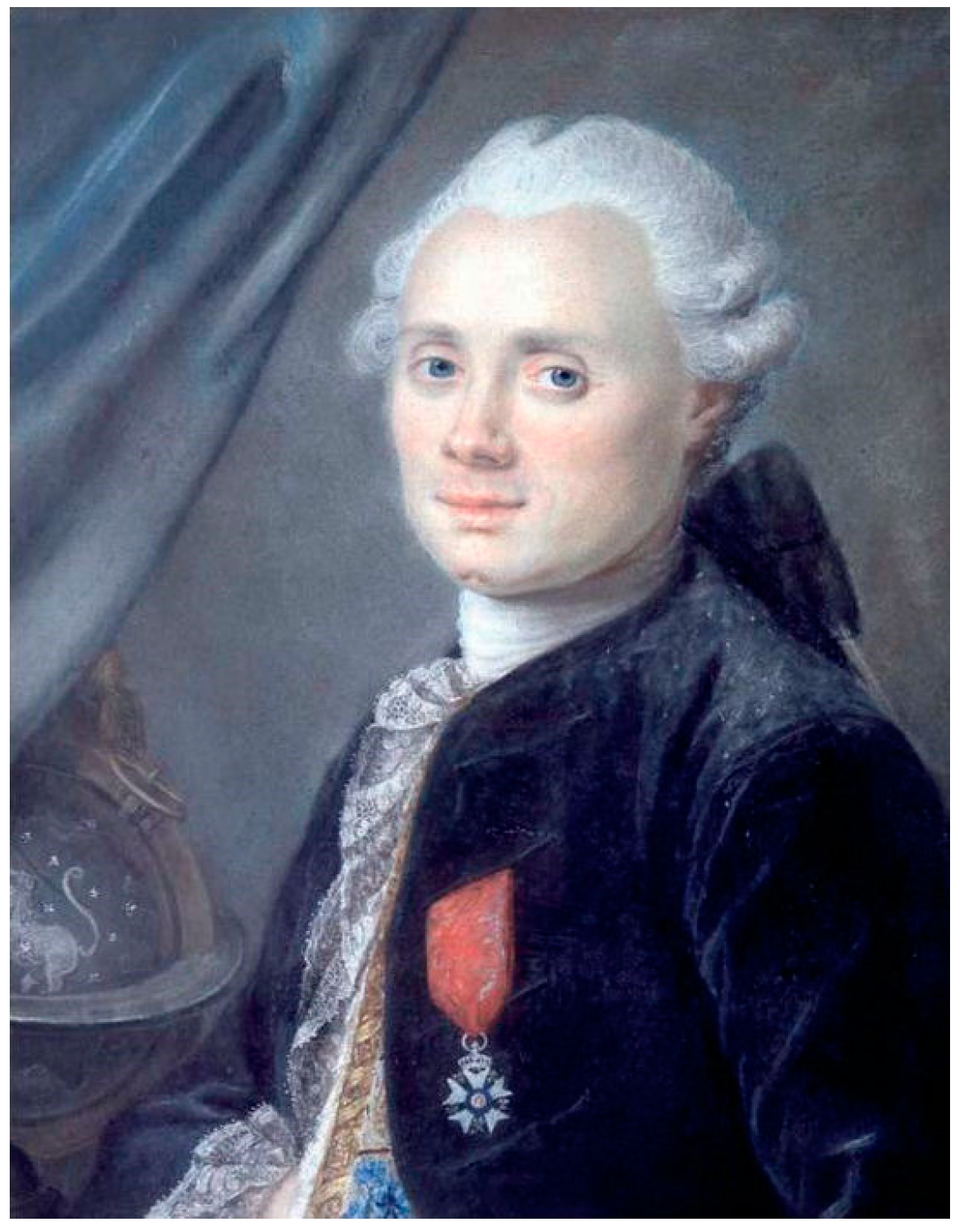
MESSIER proposal is a wide-field low-central-obstruction folded-two-mirror-anastigmat or here called briefly three-mirror-anastigmat (TMA) telescope based on a folded reflective Schmidt optical design. It is dedicated to the survey of extended astronomical objects with extremely low surface brightness. The proposal name is in homage to French astronomer Charles Messier (1730–1817) (
Figure 1) who published the first astronomical catalogue of nebulae and star clusters. The catalogue was known as
Messier objects—for instance, M1 for the Crab nebulae, M31 for the Andromeda galaxy and so forth—and distinguished between permanent and transient diffuse objects, then helped in sensing or discovering comets.
MESSIER optical design would provide a high imaging quality without any diffractive spider pattern in the beams. A preliminarily ground-based prototype is planned to serve as a fast-track pathfinder for a future space-based MESSIER mission. The elliptical freeform mirror is generated by stress polishing and elastic relaxation technique [
4,
5].
Super-polishing of freeform surfaces is obtained from spherical polishing after elastic relaxation. Preliminary analysis required use of the optics theory of 3rd-order aberrations and elasticity theory of thin elliptical plates. The final cross-optimizations were carried out with Zemax ray-tracing code and Nastran FEA elasticity code that provides accurate determination of the substrate geometry of a glass ceramic Zerodur material.
2. Optical Design with a Reflective Schmidt Concept
A reflective Schmidt design is a wide-field system and basically a two-mirror anastigmat. With one freeform surface correcting all three primary aberrations, such a system has been widely investigated as well as for telescope or spectrograph designs. The corrector mirror or reflective diffraction grating is always located at the centre of curvature of a spherical concave mirror.
Compared to a Schmidt with a refractor-correcting element, which is a centred-system, a reflective Schmidt necessarily requires a tilt of the optics. The inclination of the mirrors then forms a non-centred-system. For an f/2.5 focal-ratio, the tilt angle of the aspheric primary mirror is typically of about 10° and somewhat depending on the FoV size.
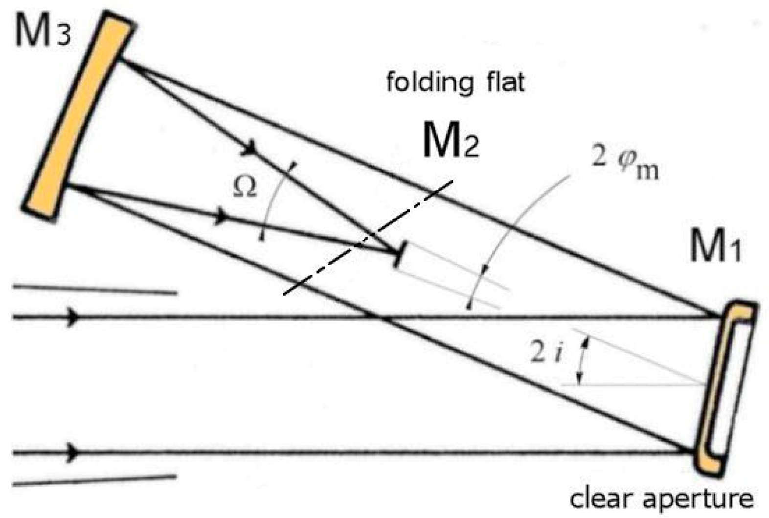
For a reflective Schmidt optical design, as MESSIER telescope proposal at f/2.5, a supplementary folding-flat mirror was found necessary. This third mirror provides: (i) an easy access to the detector for minimal central obstruction; and (ii) avoid any spider inside the beams that would cause diffractive artefact cross-like images at the focal image of bright stars. This led us to a three-mirror design or TMA telescope.
Investigations of the plane-aspheric mirror have been discussed to define the best shape freeform surface of this non-centred system. The freeform surface is with elliptical symmetry and provides balance of the quadratic terms with respect to the bi-quadratic terms.
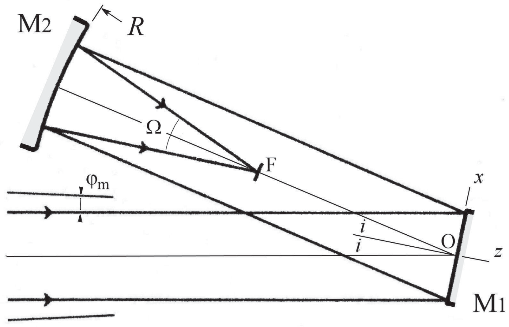
Temporarily avoiding the folding-flat mirror, let assume a two-mirror non-centred system where the primary mirror M1 is a freeform and the secondary mirror M2 is a concave spherical surface of radius of curvature
R. The input beams are circular collimated beams merging at various field angles of a telescope and define along the M1 freeform mirror an elliptical pupil due to inclination angle
i. A convenient value of the inclination angle allows the M2 mirror to avoid any obstruction and provide focusing very closely to mid-distance between M1 and M2, then very near the distance
R/2 from M1 (
Figure 2).
Let us denote
xm and
ym the semi-axes of the elliptic clear-aperture on M1 primary mirror. If the
y-axis is perpendicular to the symmetry plane
x,
z of the two-mirror telescope, one defines
a dimensionless ratio Ω, where
ym is the semi-clear-aperture of the beams in
y-direction, that is half-pupil size in y-direction. The
focal-ratio of the two-mirror telescope is denoted
f/Ω.
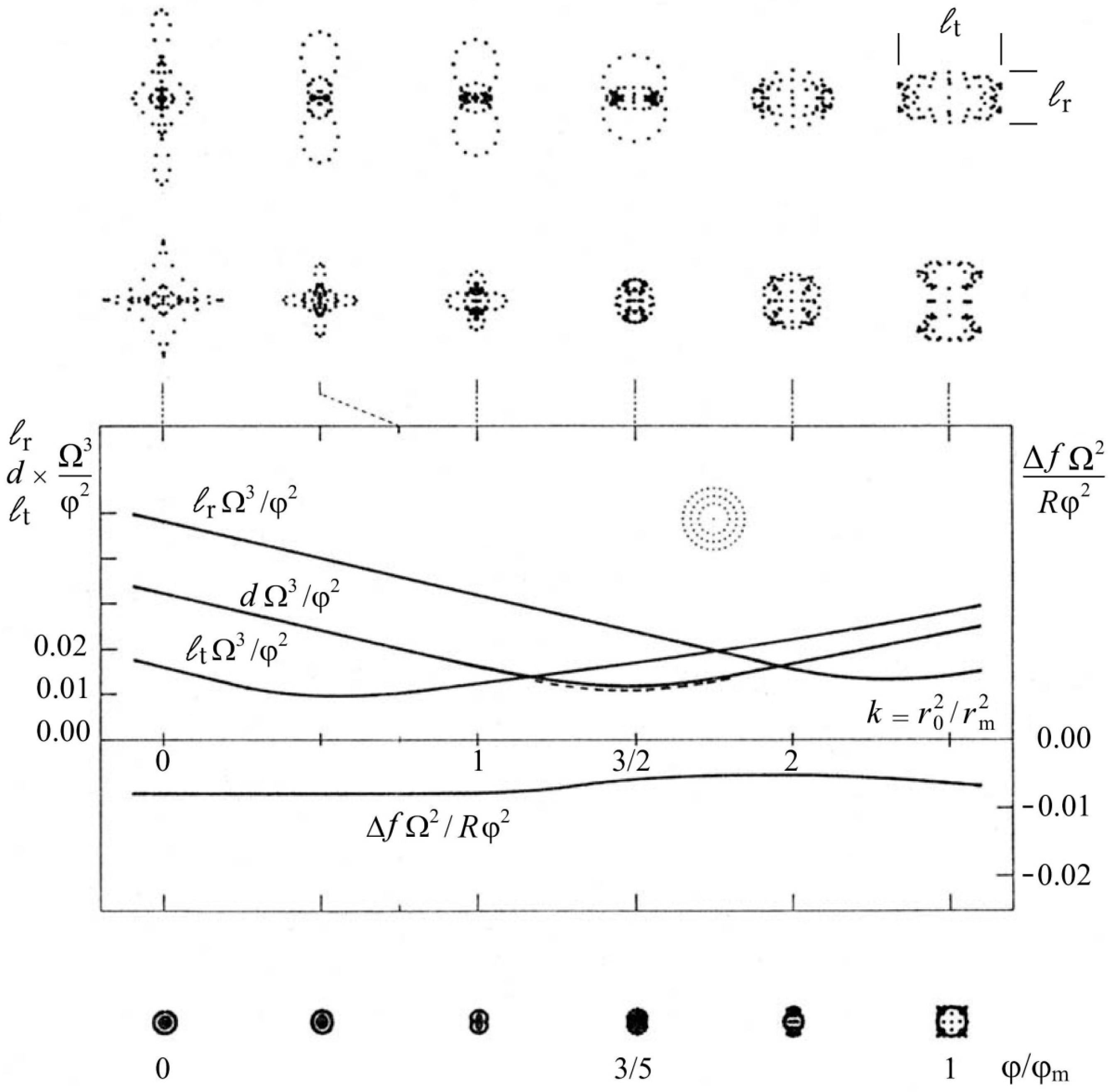
It is the interesting to investigate the performance in the field of view of a 100% obstructed two-mirror telescope which then is a centred system. Comparing the blur images, the free parameter is the ratio that characterize the meridian profile section of the primary mirror M1. This ratio, or aspect ratio, can be expressed by
k =
rO2/
rm2 where
rO is the radius of null-power zone and
rm that of clear aperture. The blur residual sizes as a function of parameter
k are displayed by
Figure 3 [
4,
6].
In order to avoid 100% beam obstruction the primary mirror M1 must be tilted at a convenient inclination angle
i. It can be shown that the shape
ZOpt of the M1 freeform mirror is an anamorphic shape and expressed in first approximation by [
4]
where dimensionless coefficients could be considered as an under-correction parameter slightly smaller than unity (0.990 <
s < 1). In fact, for a tilt angle of M1—that is a non-centred system—coefficients does not operates and must just be set to
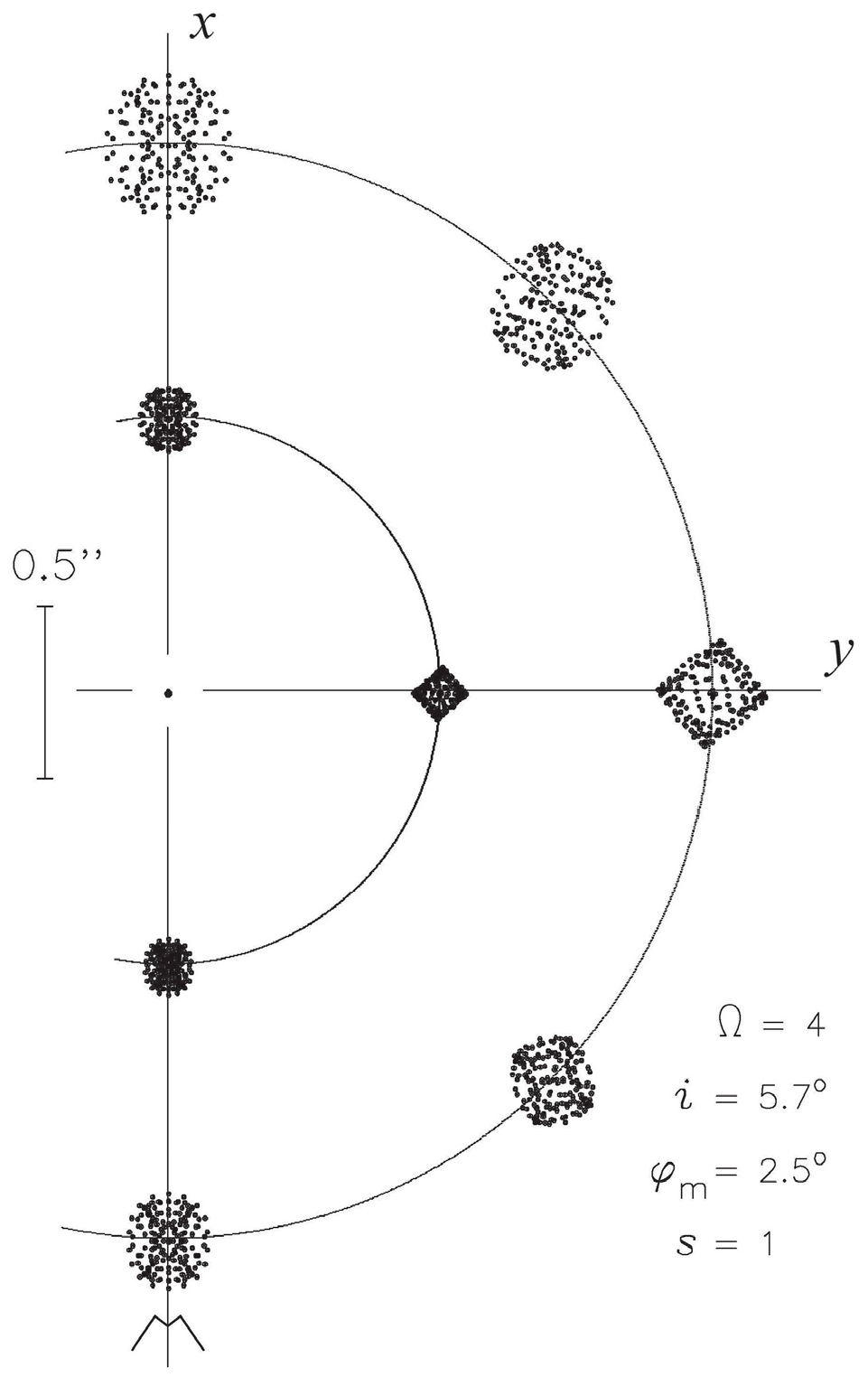
s = 1. A preliminary analysis of the two-mirror system shows that for four direction points of a circular field of view, the largest blur image occurs at the largest deviation angle of the field along the
x-axis. In
y-direction sideways blur images have an average size.
The length from the vertex O of the M1 mirror to the focus F can be derived as [
4]
showing that this distance is slightly larger than the Gaussian distance
R/2. The optimal size of blur images for an
f/4 two-mirror anastigmat telescope over the field of view are displayed by
Figure 4.
Preliminarily analyses also show that the M1 mirror shape has opposite signs between quadratic and bi- quadratic terms. The shape is given by Equation (2) and represented by
Figure 5 in either directions
x or
y in dimensionless coordinates of
ρ.
Dimensionless coordinates
z,
ρ have been normalized for a clear semi-aperture
ρ = 1, presently in the
y-direction, with a maximum sag
which leads to algebraically opposite curvatures
d2z/
dρ2 for
ρ = 0 and
ρ = 1.
The conclusions from the best optical design of an all-reflective two-mirror Schmidt telescope with
optimal angular resolution are the followings [
4,
6]:
For a circular incident beam, the elliptical clear-aperture of the primary mirror istimes smaller to that of the null-power zone ellipse.
The angular resolution dNCof a reflective non-centred two-mirror telescope is The primary mirror of a non-centred two-mirror system provides the algebraic balance of second derivative extremals. Therefore, its central curvature is opposite to the local curvatures at edge.
3. Elasticity Design and Deformable Primary-Mirror Substrate
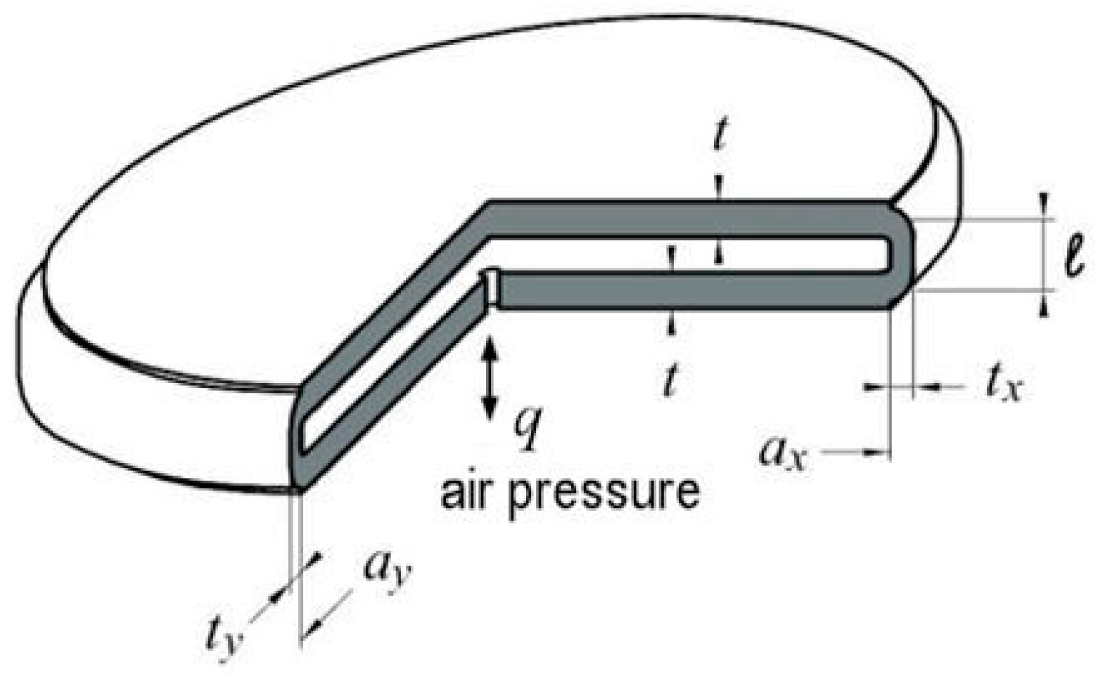
Active optics preliminarily analysis of a Schmidt-type primary mirror M1 leads to investigate deformable substrates and use of stress mirror polishing (SMP). We consider hereafter the thin plate theory of plates with development to elliptical plates.
Let consider the system coordinates of an elliptical plate and denote
n the normal to the contour
C of the surface. Equation of
C is represented by (
Figure 6)
The bi-Laplacian equation of the flexure where a uniform load
q is applied to the inner plate is [
4,
7]
where the rigidity
D is [
4,
7]
and
E the Young’s modulus,
ν the Poisson ratio and
t the constant thickness of the plate over
C.
The equation of homothetic ellipses
C(
ax,
ay) or
C′(
bx,
by) can be expressed by quadratic forms. Ellipse curve
C writes
Remaining within the optics theory of third-order aberrations, such optical freeform surfaces can be obtained from elastic bending by mean of the following conditions:
a flat and constant-thickness plate, t = constant,
a uniform load q applied to inner surface of substrate,
and a link at the edge to an elliptic contour expressed by a built-in edge, or a clamped edge, that is where the slope is null all along the contour C of the plate.
Assuming that the three conditions below are satisfied, the analytic theory of thin plates allows deriving a biquadratic flexure
ZElas(
x,y) in the form [
4,
7],
where
z0 is the sag at origin and where
ax and
ay are semi-axes corresponding to the elliptic null-power zone of the principal directions of contour. The flexural sag
z0 is obtained from substitution of Equation (9) into biharmonic Equation (6). This leads to
The null-power zone contour
C is larger by a factor
to that of the clear-aperture (cf.
Figure 3).
The dimensions of semi-axes
ax and
ay at
C of the built-in ellipse – or null-power zone –relatively to that of clear-semi-apertures
xm and
ym are
From Equations (2) and (1), in setting
s = 1 and
x = 0 and for the built-in radius
of the vase form, we obtain the amplitude of the flexure
z0 in Equation (9), as
From Equations (10)–(12) we obtain, after simplification, the thickness
t of the inner plate
This defines the execution conditions and elasticity parameters of an elliptical plate where the clear aperture of primary mirror M1 uses a somewhat smaller area than the total built-in surface as delimited by ellipse C.
The conclusions from a best optical design of the primary mirror M1 of a two-mirror Schmidt telescope, as corresponding to the profile displayed by
Figure 3, are as follow [
4]:
A built-in elliptic vase-form is useful to obtain easily the primary mirror of a two-mirror anastigmat.
The elliptic null-power zone at the plate built-in contour istimes larger than that of the elliptic clear-aperture of the primary mirror.
The total sag of the built-in contour is 9/8 times larger than that of its optical clear-aperture.
The optimization of a built-in substrate, of course, requires losing some of the outer surface which then is not usable by an amount of 33% outside the clear-aperture area. It is clear that a flat deformable M1 substrate, conjugated with an elliptic inner contour, provides most interesting advantages in practice with a
built-in condition (
Figure 7).
An extremely rigid outer ring designed for a
closed vase form, while polished flat at rest, allows the primary mirror to generate by uniform loading a bi-symmetric optical surface made of
homothetic ellipses (
Figure 8).
The case of a perfect
built-in condition was applied to the design and construction of several aspherized grating spectrographs (4) such as UVPF of CFHT, MARLYs of OHP and PMO, CARELEC of OHP, OSIRIS of ODIN space mission. It was recently applied to the design and construction of aspherized gratings for the FIREBall balloon experiment [
8] using a 1-meter telescope and multi-object spectrograph. The processing was as follows: (i) A plane reflective diffraction grating was first deposited on a deformable stainless steel matrix without stressing; (ii) the freeform bi-quadratic surface of this deformable matrix was bent by inner air pressure loading; (iii) the freeform gratings were obtained from resin replication during controlled stressing onto Zerodur vitro ceramic rigid substrate; and (iv) final aspheric shape of the gratings was obtained by elastic relaxation [
4] (
Figure 9).
Compared to the case of or a deformable M1 mirror—or a deformable matrix—where a perfect built-in condition leads to some outside loosen optical area of the freeform (a clear aperture somewhat smaller to that of the built-in zero power zone), we investigate hereafter a closed-form substrate with a radially thinned outer elliptic cylinder. The optimized freeform surface for MESSIER proposal will then provide almost the telescope theoretical angular resolution by use of a semi-built-in edge condition of the mirror substrate.
4. A TMA Telescope Proposal for MESSIER
Our proposal of MESSIER experiment is named in honour to French astronomer Charles Messier who started compiling in 1774 his famous Messier Catalogue of diffuse non-cometary objects. For instance the Crab Nebulae, named object ”M1,” is a bright supernova remain recorded by Chinese astronomer in 1054. The present MESSIER proposal is dedicated to the detection of extremely low surface brightness objects. A detailed description of the science objectives and instrument design for this space mission can be found in [
9].
A three mirror anastigmat (TMA) telescope proposal should provide detection of extremely low surface brightness. MESSIER science goals require that any optical design should deliver a detection as a detection as low as 32 magnitude/arcsec2 in the optical range. A space-based telescope option should provide 37 magnitude/arcsec2 in UV at 200 nm. The preliminary ground-based telescope here investigated as a prototype should be useful for spectral ranges in blue, red and infrared regions. The main features require a particular optical design as follow:
a wide field three mirror anastigmat telescope with fast f-ratio,
a distortion-free field of view at least in one direction,
a curved-field detector for a natural curved reflective Schmidt,
a time delay integration by use of drift-scan techniques,
no spider in the beams can be placed in the optical train.
The final space-based proposal, restrained to extremely low brightness objects in ultraviolet imaging, would be a 50-cm aperture telescope. For the optical range, our preliminary plan for MESSIER is to develop and build a 30-cm aperture ground-based telescope fulfilling all above features of the optical design. Preliminary proposed designs can be found in [
5,
10].
4.1. Optical Design and Ray Tracing Modelling
Before studying a space model, we propose development of a ground-based prototype telescope is a three-mirror anastigmat (TMA) with an f-ratio at f/2.5.
One may notice a classical design as a two-element anastigmat design where the first optical element is a refractive aspherical plate. Minimization of field aberrations is achieved by a balance of the slopes—that is balance of 1st-order derivative—where sphero-chromatism variations are dominating aberration residuals.
Now using a mirror—instead of a refractive plate—as a first element M1 of a two-mirror anastigmat, the best angular resolution over the field of view is achieved by a
balance of meridian curvatures—that is balance of the 2nd-order derivative—of the aspherical mirror or diffraction grating [
4].
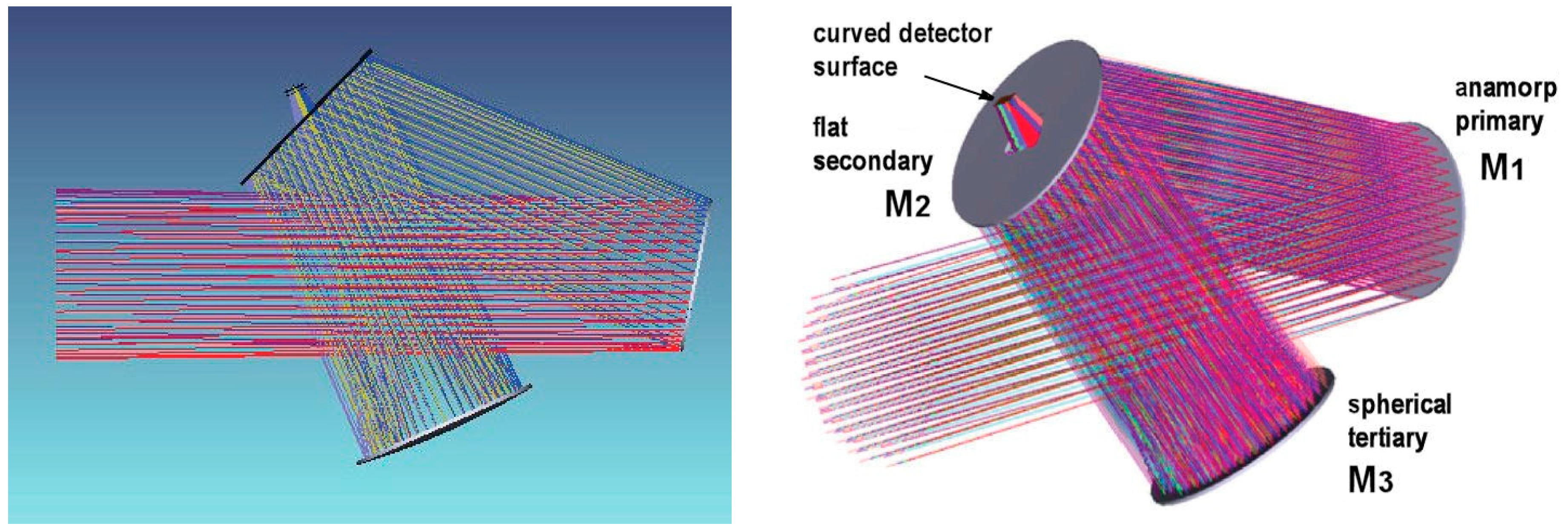
The proposed design is made of freeform primary mirror M1, followed by holed flat secondary mirror M2 and then a spherical concave tertiary mirror M3. The centre of curvature of M3 is located at the vertex of M1which is a basic configuration for a reflective Schmidt concept. The unfolded version, with only two mirrors, do not alter anastigmatic image quality (Figure 13). The optics parameters are optimized for a convex field of view (
Table 1). The three-mirror system gives unobstructed access to detector and avoid any spider in the field of view (
Figure 10 and
Figure 11).
The primary mirror surface M1 can be defined by the aspheric anamorphic equation as derived from Zemax optics ray-tracing code—which is somewhat similar to Equaiton (2)—and denoted
where now in all this section with Zemax code (
y,
z) is the symmetry plane of the telescope.
Restraining to the case of a simply bi-curvature surface for the first quadratic term, then setting Kx = Ky = −1, denominator reduces to unity. The result from Zemax modelling optimization provides the four coefficients, Cx = −3.598 × 10⁻⁶ mm−1, Cy = −3.467 × 10⁻⁶ mm−1, AR = 2.203 × 10⁻¹¹ mm−3 and AP = −0.01854.
The
total sag of clear aperture in
x-direction (i.e., off-symmetry plane) for
xmax = 178 mm is then
ZOpt−max = −35.70 µm.
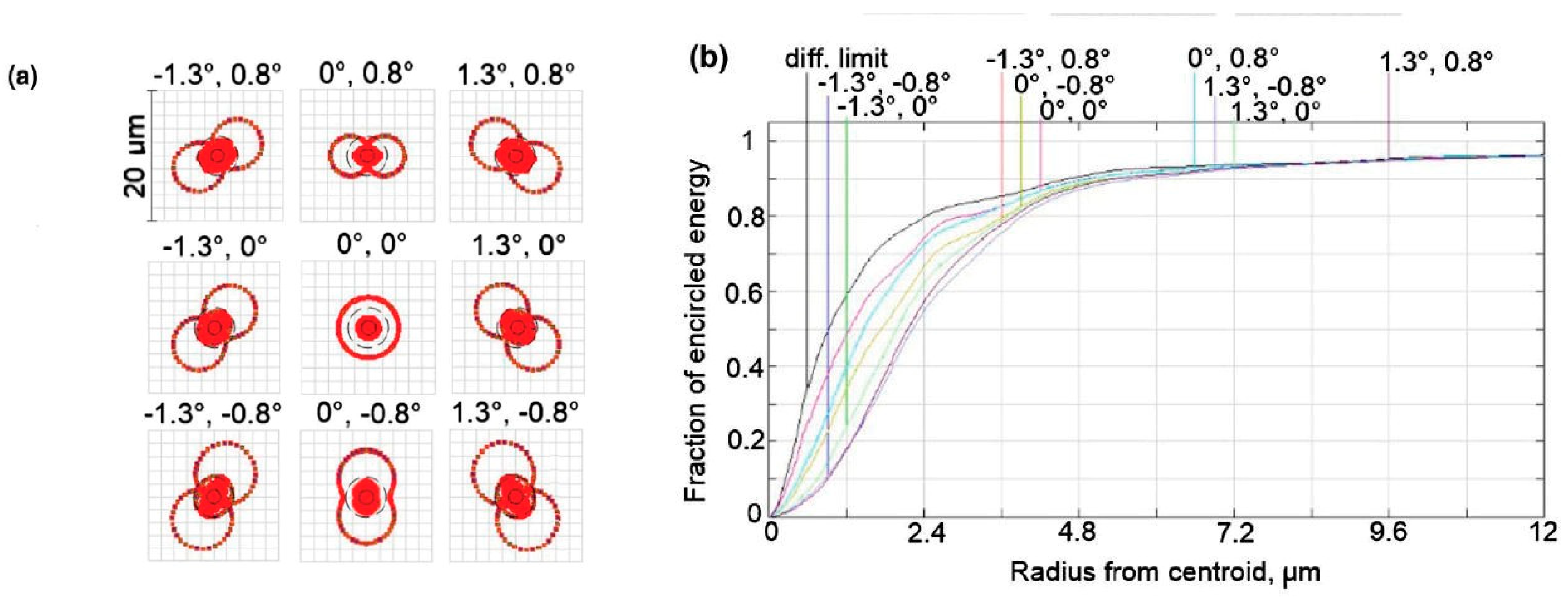
Zemax iterations lead to RMS residual blur images in agreement with predicted angular resolution (
Figure 12).
Results from Zemax modelling and spot diagram one shows that the maximum RMS blur residuals is
ϕZemax = 5.5 µm or
dNC = 1.27 arcsec. From Equation (5) and a same diagonal semi-FOV (1.52°) and same parameters in
Table 2, one also obtains for MESIER proposal the theoretical angular resolution [
4,
6],
showing that results from modelled and theoretical angular resolutions are similar.
One of the key requirements was to provide a free distortion design. Over a diagonal field of view of maximum radius ° it was shown that for a curved FoV distortion Δφ/φm remains smaller than 2 × 10⁻⁴ and thus is negligible.
The telescope image quality is estimated through its spot sizes in the diagram. Diagram indicates an image quality convenient for seeing limited conditions and close to the diffraction limit. Contribution of residual aberrations is 1.3 arcsec RMS over the field of view.
Residual spot radius values take into account a UBK7 colour filter 2 mm thick where a spectral band can be selected in a filter wheel with 5 wavebands. An optional 5 mm thickness SiO
2 cryostat window is planned for optical design of the ground-based prototype telescope (
Table 2).
4.2. Elasticity Modelling of a Freeform Primary Mirror
The requested aspheric surface with non-rotational symmetry of the primary mirror surface refers to an optical surface also called a
freeform surface. The present freeform surface for our MESSIER primary mirror is made of
homothetic-ellipse iso-level lines. This surface is to be designed through active optics methods where the deformable substrate is aspherized by a plane surfacing under stress—an active optics method also called stress mirror polishing (SFP). The principle uses a uniform load applied and controlled inside a
closed vase form whilst a plane polishing is operated with a full-size tool. The final process delivers the required shape after elastic relaxation of the load [
5,
6,
10,
11].
The
closed vase form—or
closed biplate—is made of facing twin elliptical vase form blanks in Zerodur assembled together at the end of their outer rings through a layer of 100–150 µm thickness 3M DP490 Epoxy, where elasticity constants are Poisson’s ratio
ν = 0.38 and Young’s modulus
E = 659 MPa [
12]. Elasticity constants of the blanks in Zerodur are Poisson’s ratio
ν = 0.243 and Young’s modulus
E = 90.2 GPa (
Figure 13).
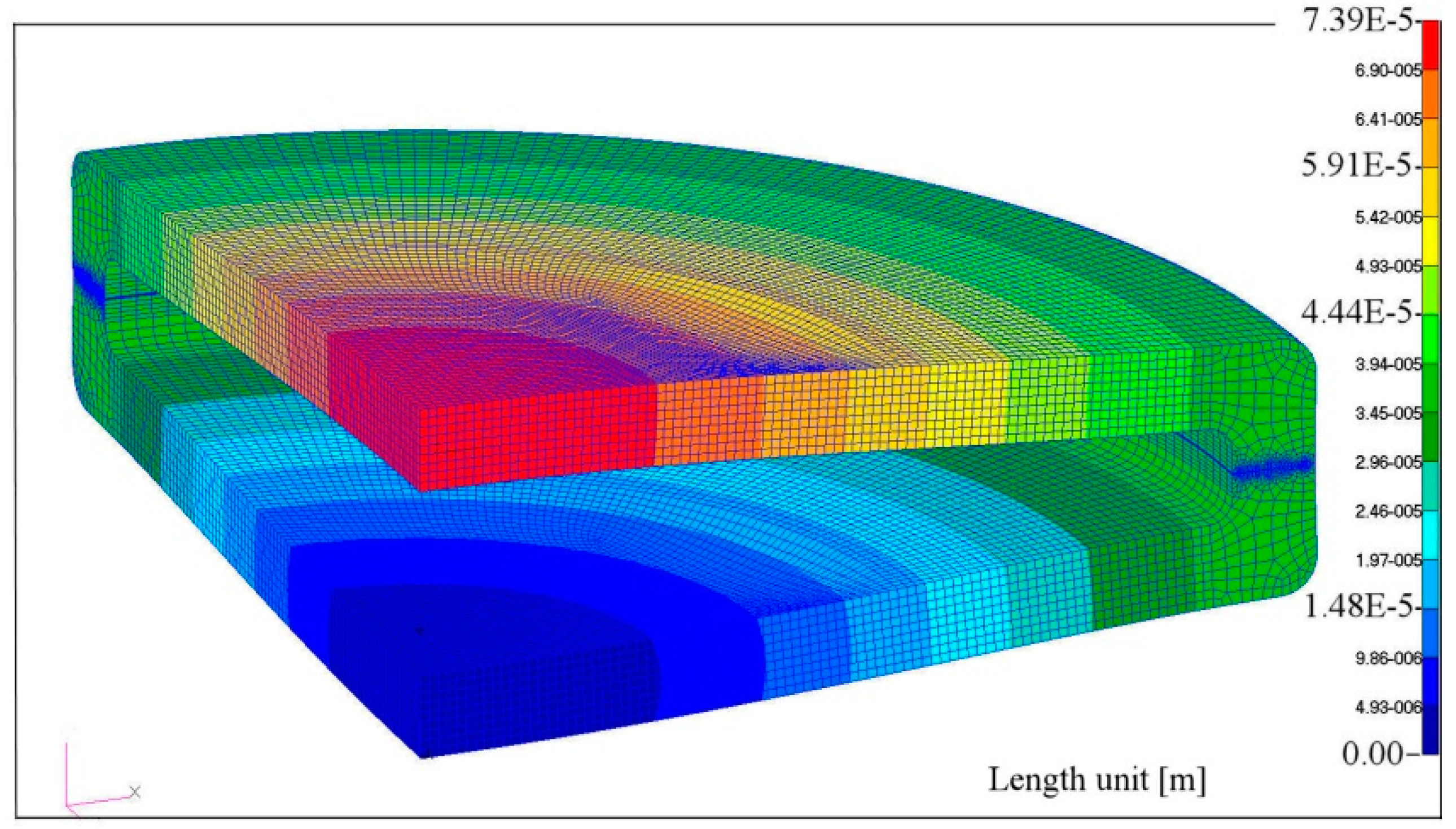
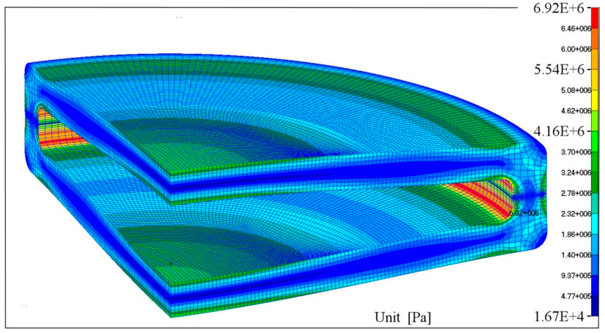
Modelling with Nastran code led us to make cross optimizations with Zemax code. The intensity of uniform loading
q and final geometry of the
closed vase form mirror substrate are displayed by
Table 3. The final finite element modelling by Pascal Vola display the displacements (
Figure 14) and stresses (
Figure 15).
The general law of algebraically balancing the second-order derivatives applies on principal directions of a pupil mirror—as stated by Equation (4)—for a circular or elliptical clear aperture. In dimensionless coordinates and any x or y orthogonal directions, if the clear aperture radii is denoted ρm, then we must obtain algebraically opposite local curvature values for ρ = 0 and ρ = ρm.
One has shown [
4] that with a perfect built-in condition – that is for a closed vase form with moderate ellipticity and a ring of large radial thickness, say, at least five times larger than the plate axial thickness—the flexure provides an elliptic
null-power zone radius
ρ0 where the size of the
clear aperture radius
ρm is in the ratio
ρ0/
ρm =
1.224. This means that the useful optical area is convenient for
ρ ∈ [
ρm,
ρ0] but unacceptable for
ρ ∈ [
ρm,
ρ0].
From our cross optimizations with Zemax and Nastran codes the ring of the closed vase form provides a noticeable decrease in flexural rigidity, which is equivalent to a
semi-built-in condition. Then, compared to a perfect built-in assembly and from our results described in latter subsection, the radii ratio between null-power zone
ρ0 and clear aperture
ρm has become after optimized modelling
This ratio is significantly smaller than 1.224. Then from Zemax ray tracing optimizations, we now take benefit of an important result: the angular resolution is not substantially modified in using the optical surface also up to the inner zone of the ring. The flat deformable surface of the closed vase form requires use of stress polishing by plane super-polishing, which then avoids any ripple errors of the freeform surface.
Closed vase form Messier primary mirror can be aspherized up to its inner part of the semi-built-in elliptic ring without any lost in optical area and angular resolution.
4.3. Optical Testing of MESSIER Freeform Primary Mirror
Optical testing of the freeform primary mirror must be a precise measurement because of its anamorphic shape. From Equation (14) the clear aperture shape presents a total sag of
ZOpt−max = −35.70 µm for
xmax = 178 mm in
x-direction, that is in the off-symmetry telescope plane. Several optical tests could be considered mainly based on a null-test system [
6]. For instance this involves lens compensators [
13] and computed-generated holograms [
14] and their combinations.
We adopted a singlet lens compensator as component already existing at the lab and providing exactly the correct compensation level of the rotational symmetry mode, that is, 3rd-order spherical aberration compensation of M1 primary mirror. This lens, also called Fizeau or Marioge lens, is plano-convex made in Zerodur-Schott with following parameters, axial thickness
tL = 62 mm,
R1L = ∞,
R2L = 1180 mm,
DL = 380 mm, used on elliptical clear aperture 356 × 362.7 mm. The axial separation to primary mirror is 10 mm. Remaining aberration is then a balanced anamorphose term to be accurately calibrated by He-Ne interferometry (
Figure 16).
Another important feature of MESSIER telescope proposal is the selection of a
curved detector,
RFOV −
f = −
R3/2 (cf.
Table 1), which allows a
distortion free design over an active area of 40 × 25 mm
2. This technology is presently under development by use of either
variable curvature mirrors (VCMs) or
toroid deformed mirrors [
4,
5]. References can be found on curved detectors in Muslimov paper [
15].
5. Conclusions
Modelling of freeform surfaces by development of active optics techniques or stress mirror polishing provides extremely smooth surfaces. Generated from elastically relaxed plane or spherical polishing with full-size aperture tools these surfaces are free from ripple errors.
Applied to MESSIER TMA telescope proposal the best angular resolution of a non-centred optical designs corresponds to a primary mirror freeform optical surface made of homothetic elliptical isolevel lines. It has been shown that this leads to algebraic balance of local curvatures – that is balance of second derivatives of the optical surface
Beside the facility to obtain easily a freeform aspheric from elastic relaxation of a closed vase form primary mirror, MESSIER proposal would also benefit from free distortion because of its naturally curved FoV. This field curvature shall be associated to a curved detector.


