Article

Magnetic Field Analytical Solution for Non-homogeneous Permeability in Retaining Sleeve of a High-Speed Permanent-Magnet Machine

by
Gabriel A. Mendonça
*,
Thales A. C. Maia
and
Braz J. Cardoso Filho
Departamento de Engenharia Elétrica (DEE), Universidade Federal de Minas Gerais (UFMG), Belo Horizonte, MG 31270-901, Brazil
*
Author to whom correspondence should be addressed.
Math. Comput. Appl. 2018, 23(4), 72; https://doi.org/10.3390/mca23040072
Submission received: 9 October 2018 / Revised: 6 November 2018 / Accepted: 7 November 2018 / Published: 10 November 2018
(This article belongs to the Special Issue Mathematical Models for the Design of Electrical Machines)

Abstract

:
This work presents a novel solution for magnetic field calculation in two-dimensional problems in which one region is defined with space-varying magnetic parameter. The proposed solution extends the well-established Maxwell–Fourier method for calculating magnetic fields in surface-mounted cylindrical high-speed permanent-magnet machines. This contribution is effective to evaluate more realistic magnetic parameters, where measurements of a high-speed permanent-magnet generator prototype indicate saturation in the retaining sleeve due to pole-to-pole leakage flux. The saturation profile is a function of mechanical angle and can be modeled with the aid of a space-varying relative permeability, expressed in terms of a Fourier series. As an example, the presented solution has been applied to a surface-mounted PM machine at no-load condition. Magnetic field calculations show that a simple saturation profile, with low order space-varying permeability in the retaining sleeve significantly affects the magnetic flux density distribution in the air-gap. The analytical solution is confronted with finite-element method, which confirms validity of the proposed methodology.

1. Introduction

An increasing interest in high-speed (HS) machines are noticeable throughout several applications, ranging from distributed energy resources to medical equipment [1,2]. These machines commonly use permanent-magnet (PM) due to high torque per unit volume and low rotor losses [3].
For HS applications, surface-mounted PM machines usually require banding with a sleeve for retaining the PMs against centrifugal forces [4]. One important disadvantage of introducing such a component is an increased effective air-gap, where the added reluctance decreases PM excitation performance [5]. Furthermore, the addition of a conducting retaining sleeve (RS), which works as damper winding or shielding cylinder, reduces PM eddy-current losses in HS operating range [6]. Therefore, an accurate modeling of the RS is crucial for the evaluation of the PM machine overall electromagnetic behavior [7].
The modeling method plays an important role in HS machines electromagnet performance analysis. Numerical methods, such as finite-elements, provide accurate results for magnetic field, but with great computational cost. Alternatively, (semi-)analytical modeling based on the formal solution of Maxwell’s equations provides precise calculation of magnetic field distribution in different machine regions. Compared with finite-element method (FEM), this approach is based on strong and limiting assumptions for both geometrical and physical parameters, however, with lower computation time and greater insight into the problem. (Semi-)analytical techniques are considered powerful tools, being vastly used in HS machine early design stage [1,2,3,6,8,9].
The available literature on (semi-)analytical technique for PM machine evaluation is extensive, with published papers ranging over twenty-five years, to the best of the authors’ knowledge [10,11,12]. Moreover, there is still great effort towards methods with better accuracy and less restricting assumptions [4,13,14,15,16,17,18,19,20,21,22] to list a few recently published works. Dubas et al. [23] realized an overview on the existing (semi-)analytical models in Maxwell–Fourier methods (vis., multi-layer models, eigenvalues model, subdomain technique and hybrid models) with the effect of local/global saturation. Further details, advantages and disadvantages of these techniques can be found in [23,24,25]. Ramakrishnan et al. [13] presented a comprehensive comparison of analytical methods, where a subdomain technique exceeded the others in terms of accuracy with reasonable calculation time.
Furthermore, extending the limitations discussed in [25], recent developments include more realistic geometric structures, such as tooth-tips [14,15,16,26,27,28] or rotor eccentricity [27,29]. Chebak et al. [30] and Rahdeh et al. [31] defined more realistic magnetic parameters, but in slotless topologies. Qian et al. [29] and Ortega et al. [32] evaluate several geometries and physical imperfections expected from manufacturing processes. Spranger et al. [33] and Dubas et al. [23,24] have recently developed new techniques to account for finite soft-magnetic permeabilities, respectively: (i) in the multi-layer model using the Cauchy’s product theorem [33], and (ii) in the subdomain technique by applying the superposition principle in both directions [23,24]. As discussed by Hannon et al. [34], both methodologies are very effective since they enable the magnetic field calculation in the ferromagnetic material of slotted geometries. The subdomain technique has been improved to consider soft-magnetic material permeability in radial-flux electrical machines, such as switched reluctance machines [21] and spoke-type PM machines [4]. In addition, this technique has been extended to the thermal modeling for the steady-state temperature distribution in rotating electrical machines [22]. According to Pfister et al. [35], the first work on the semi-analytical subdomain technique was published by [36] with the state-of-the-art in the introduction. Moreover, the method based on the Cauchy’s product theorem has been improved to account for saturation in stator tooth [19] and a configurable model, adaptable to many machine geometries [20].
However, among the presented references, a small number of authors give a proper realistic evaluation for RS [3,6,9,14,18,28]. Furthermore, only a few of these works evaluate all electromagnetic properties of the retaining sleeve, where relative permeability is different from the air [14,18] and eddy-currents are considered [3,6,9,18,28].
In this paper, a novel formulation is presented to extend a two-dimensional analytical solution from Laplace’s and Poisson’s equation in polar coordinates. The proposed technique allows the definition of periodic space-varying magnetic parameter, which is defined through Fourier series. A similar approach was used by Sprangers et al. [33], where permeability variation in slotted regions was evaluated directly into the field solution. Such method, based on the convolution theorem, allows the calculation of magnetic field in the tooth region, where interactive solutions can be applied to evaluation of magnetic saturation [19]. The technique presented in this paper, based on well-established Maxwell–Fourier method solutions, evaluates the space-varying permeability by reexamining the boundary conditions. Therefore, the proposed analysis provides an intuitive and fast solution to problems involving magnetic saturation of an annular region and can be extended to other analytical techniques, e.g., the subdomain method for evaluating slotting effects.
Finally, validation of the proposed model is carried out based on a two-pole surface-mounted permanent-magnet generator prototype [37], where experimental data indicated saturation in the retaining sleeve. The geometry and magnetic parameters of the PM generator are approximated, thus providing simplified formulation. The derived model is, then, evaluated with different saturation characteristics and the results are compared with those obtained from FEM.

2. Geometry and Mathematical Formulation

Throughout the literature, great efforts are invested in developing and improving analytical models focused on the early design stages, where optimization routines play an important role. This work is based on the performance of a HS machine prototype and justifies the reevaluation of common approximations. Thus, the model presented is implemented to include a space-varying permeability to evaluate magnetic saturation effects of the retaining sleeve. Moreover, several other machine aspects not related to the present method are simplified, such as machine geometry and some magnetic parameters, as discussed in this section.
The proposed method is derived according to well-established analytical solution of Maxwell’s equations. The saturation phenomenon in the RS is mainly due to pole-to-pole leakage flux, thus changing the RS relative permeability in the tangential direction. In a first approximation, this behavior is considered as independent on loading conditions and the machine is studied evaluating only PM magnetization. Furthermore, stator iron core is assumed to present linear and very large relative permeability, assumed to be infinite. The PM do not demagnetize. All electrical conductivities are assumed to be null. Finally, the magnetic field solutions are derived considering a slotless geometry, as illustrated in Figure 1.
These approximations are necessary to simplify the analytical model and must be used with care. The objective is to derive simpler mathematical formulation, allowing better insight of the proposed method. However, to fully investigate PM machine performance, further research must be done to evaluate more realistic geometry and electromagnetic parameters, such as slotting effects, conducting regions and loading influence.
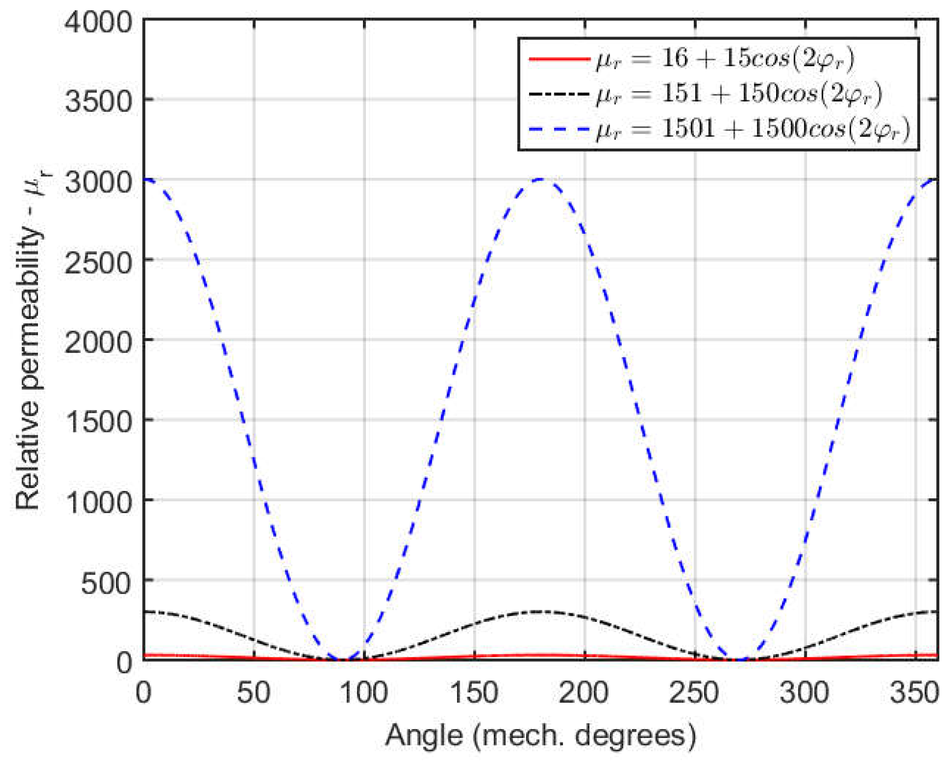
The remainder of assumptions are necessary to evaluate the two-dimensional analytical problem using Fourier series representation. Magnetic field end effects are neglected and all parameters are periodic in respect to the tangential coordinate. In the RS region, saturation occurs from pole-to-pole leakage flux, where the resultant relative permeability is a function of rotor mechanical angle and varies periodically from pole-to-pole. Therefore, it can be characterized as periodic in the circumferential direction with fundamental space period equals to 2 p , where p is the number of pole pairs. The relative permeability distribution is defined in terms of a Fourier series as
μ r φ = k = 0 , 1 , 2 , 3 , μ ^ r , k cos ( 2 p k φ r ) ,
where μ r is the space-varying relative permeability.
The Fourier coefficients μ ^ r , k can be calculated accordingly for the evaluated phenomenon. For example, to estimate saturation in an annular region, an iterative method could be used to account for the nonlinear magnetic material.

The Poisson’s Equation Solution

Considering previous approximations, the basis for the analytical solution for the air-gap magnetic field is set. Using the magnetic vector potential, and using the Coulomb gauge, the general governing equation for the defined regions is
2 A = × B r e m .
The general solution to Poisson’s Equation (2) is determined in each annular region depending on their electromagnetic characteristic and can be expressed as
A z ( v ) r , φ = k = 1 , 3 , 5 , A ^ z , k ( v ) ( r ) sin k p φ r ,
where:
A ^ z , k ( v ) ( r ) = C k ( v ) r k p + D k ( v ) r k p + A ^ p a r t , z , k ( v ) r .
In the present investigation, where focus is given to characterize saturation in the RS region, PM magnetization pattern and topology does not need to be determined. These aspects are needed, however, to obtain the particular solution, A ^ p a r t , z , k ( v ) , in (3b). Further discussion on this particular solution from different magnetization profiles (e.g., parallel, radial, Halbach, etc.) can be found in [3,6,10,31,36]. Regions where no magnetic field sources are defined, namely air-gap and RS, the Poisson’s equation (1) simplifies to the corresponding Laplace’s equation. The solution is also obtained from Equations (3a) and (3b), where the particular solution is null, i.e., A ^ p a r t , z , k ( v ) = 0 .
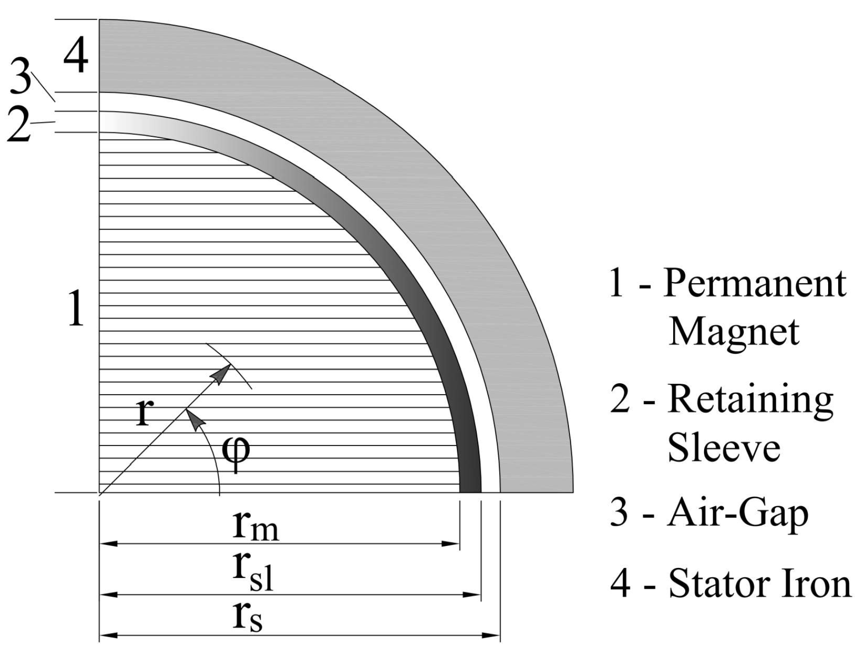
The magnetic vector potential in region v, A z ( v ) , is described through an infinite series of space harmonics k. The regions are defined according to
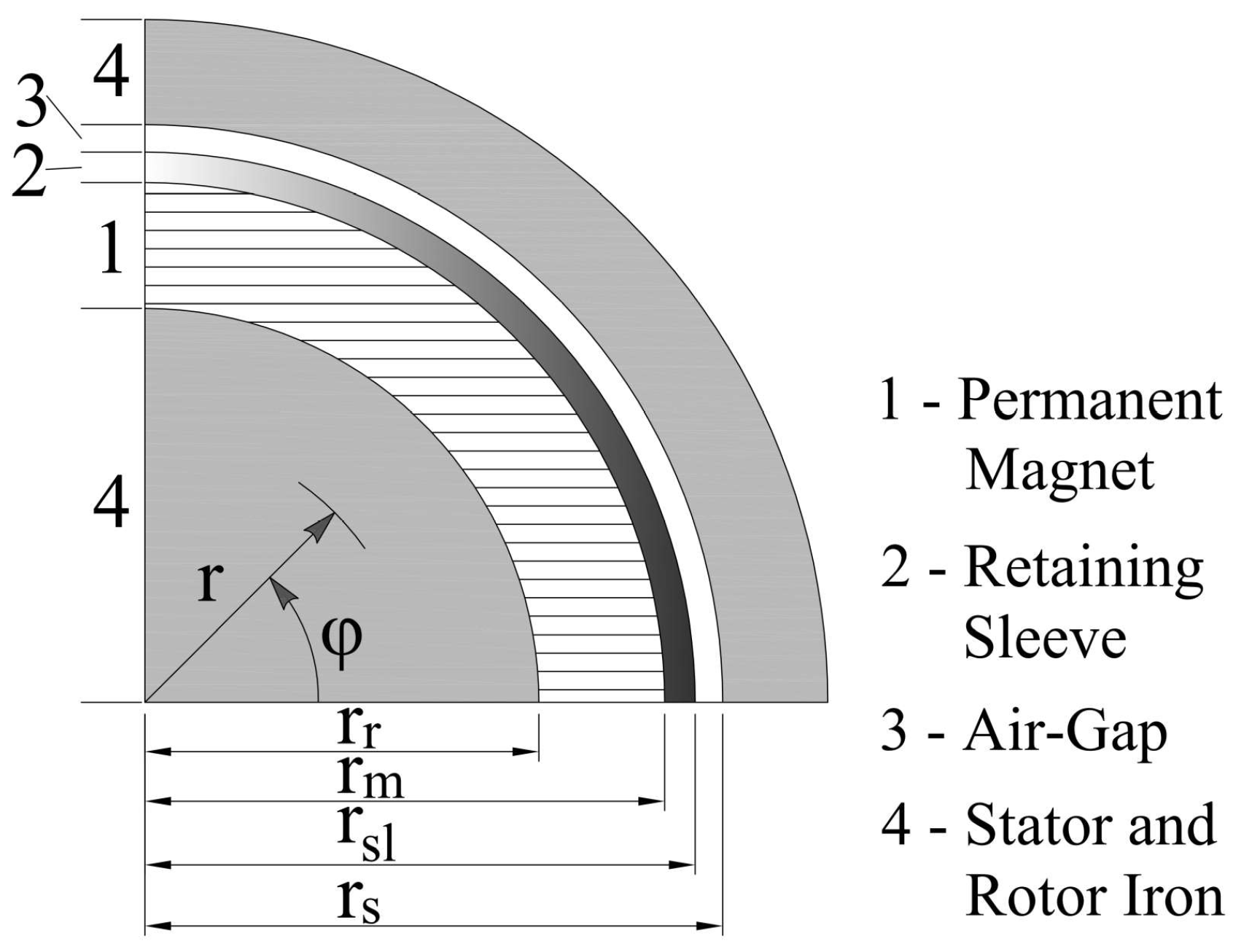
 Figure 1, where v = 1 , 2 and 3 for PM, RS and air-gap, respectively. Rotor reference frame, φ r , is defined from magnetization axis. Finally, the constants C k ( v ) and D k ( v ) are determined from the boundary conditions, which are defined by the continuity of the tangential field intensity, H φ , and the normal flux density, B r and expressed as
H φ ( v + 1 ) r v , φ H φ ( v ) r v , φ = K z ( v ) φ ,
B r ( v + 1 ) r v , φ B r ( v ) r v , φ = 0 .
The surface density current, K z ( v ) , is usually defined along the z-axis, being positive in the out-of-the-page direction. Equations (3a) and (3b)–(5) are the basis to the field solution procedure. The analysis is usually simplified, since space harmonics of different orders are orthogonal. Hence, the constants C k ( v ) and D k ( v ) are related only to the field source space harmonic component of the k-th order, being either from PM or current sources.
The present formulation is based on the reevaluation of such criteria. Reexamining the magnetic flux density tangential component boundary condition for the interfaces of the RS, Equation (4), with the proposed relative permeability in (1), that is
B φ ( 2 ) r s l , φ μ r ( φ ) μ 0 = B φ ( 3 ) r s l , φ μ 0 ,
B φ ( 1 ) r m , φ B r e m , φ φ μ 0 = B φ ( 2 ) r m , φ μ r ( φ ) μ 0 .
With the tangential component for magnetic flux density calculated from the magnetic vector potential Equations (3a) and (3b), Equation (6) can be rewritten as
1 μ r ( φ ) k = 1 , 3 , 5 , B ^ φ , k ( 2 ) ( r s l ) sin k p φ r = k = 1 , 3 , 5 , B ^ φ , k ( 3 ) ( r s l ) sin k p φ r ,
where B ^ φ , k ( v ) ( r ) = k p C k ( v ) r k p 1 D k ( v ) r k p 1 + A ^ p a r t , z , k ( v ) r r . The solution, with relative permeability defined with (1), includes multiple summation terms. For generalization purposes, these summation indexes are defined with different variables, k, m and n. Thus, from (8), we have
k = 1 , 3 , 5 , B ^ φ , k ( 2 ) ( r s l ) sin k p φ r = m = 0 , 1 , 2 , 3 , μ ^ r , m cos 2 m p φ r n = 1 , 3 , 5 , B ^ φ , n ( 3 ) ( r s l ) sin n p φ r .
The calculation of the constants and proper interaction of the different space harmonic indexes are found from the definition of Fourier series. Therefore, if we establish
f φ r = k = 1 , 3 , 5 , B ^ φ , k ( 2 ) sin k p φ r ,
the constants in (10) are determined from
B ^ φ , k ( 2 ) = 1 π 0 2 π f φ r sin k p φ r d φ .
Rearranging the right-hand side of (11) with the aid of (9) yields
B ^ φ , k ( 2 ) ( r s l ) = m = 0 , 1 , 2 , 3 , n = 1 , 3 , 5 , μ ^ r , m B ^ φ , n ( 3 ) ( r s l ) π 0 2 π sin n p φ r cos 2 m p φ r sin k p φ r d φ ,
where the space harmonic index k can be thought as a reference index. The integration on the right-hand side of (12) will not be null for specific values of k, m and n.The same reasoning is used for (7), that is,
B ^ φ , k ( 2 ) ( r m ) = m = 0 , 1 , 2 , 3 , i = 1 , 3 , 5 , μ ^ r , m B ^ φ , i ( 1 ) ( r m ) π 0 2 π sin i p φ r cos 2 m p φ r sin k p φ r d φ m = 0 , 1 , 2 , 3 , l = 1 , 3 , 5 , μ ^ r , m B ^ r e m , φ , l π 0 2 π sin l p φ r cos 2 m p φ r sin k p φ r d φ .
The definition of a relative permeability from Fourier series expansion results in an interaction of magnetic fields of different orders. The integrations in (12) and (13) will be different from zero only for certain values of i, k, l, m and n. The trigonometric transformations needed to evaluate integration terms in Equations (12) and (13) are well known and will not be reproduced here. Summarizing the results, Table 1 presents the relations between the indexes which results non-zero integration values in Equation (12). Though there are different indexes relations in Equation (13), the results can be easily extended by replacing n with i or l.
One first conclusion derived from Table 1 is that, assuming homogeneous and constant RS magnetic parameter, the solution is determined from interaction of magnetic fields with the same space harmonic order. In such case, for m = 0 , the linear equation systems are obtained with k = i = l = n . In addition, it is important to note that the results from the index relations must be added up accordingly with the summation notations. Therefore, from the index relations in Table 1, the result for Equations (12) and (13) can be derived as
B ^ φ , k ( 2 ) ( r s l ) = m = 0 , 1 , 2 , 3 , μ ^ r , m 2 B ^ φ , k 2 m ( 3 ) ( r s l ) + B ^ φ , k + 2 m ( 3 ) ( r s l ) B ^ φ , 2 m k ( 3 ) ( r s l ) ,
B ^ φ , k ( 2 ) ( r m ) = m = 0 , 1 , 2 , 3 , μ ^ r , m 2 B ^ φ , k 2 m ( 1 ) ( r m ) + B ^ φ , k + 2 m ( 1 ) ( r m ) B ^ φ , 2 m k ( 1 ) ( r m ) m = 0 , 1 , 2 , 3 , μ ^ r , m 2 B ^ r e m , φ , k 2 m + B ^ r e m , φ , k + 2 m B ^ r e m , φ , 2 m k .
From (14) and (15), it can be verified that the Fourier coefficients of the magnetic flux density in the non-homogeneous region, v = 2 , are related to those of different space harmonic orders of the surrounding regions, i.e., v = 1 and 3. For example, B ^ φ , k ( 2 ) is expressed in terms of B ^ φ , k 2 m ( 3 ) , B ^ φ , k + 2 m ( 3 ) and B ^ φ , 2 m k ( 3 ) , which are the Fourier coefficients of space harmonic orders ( k 2 m ) , ( k + 2 m ) and ( 2 m k ) for flux density in region v = 3 and where m is the space harmonic order of the relative permeability Fourier series. These relations will be further detailed in the application example (Section 4).
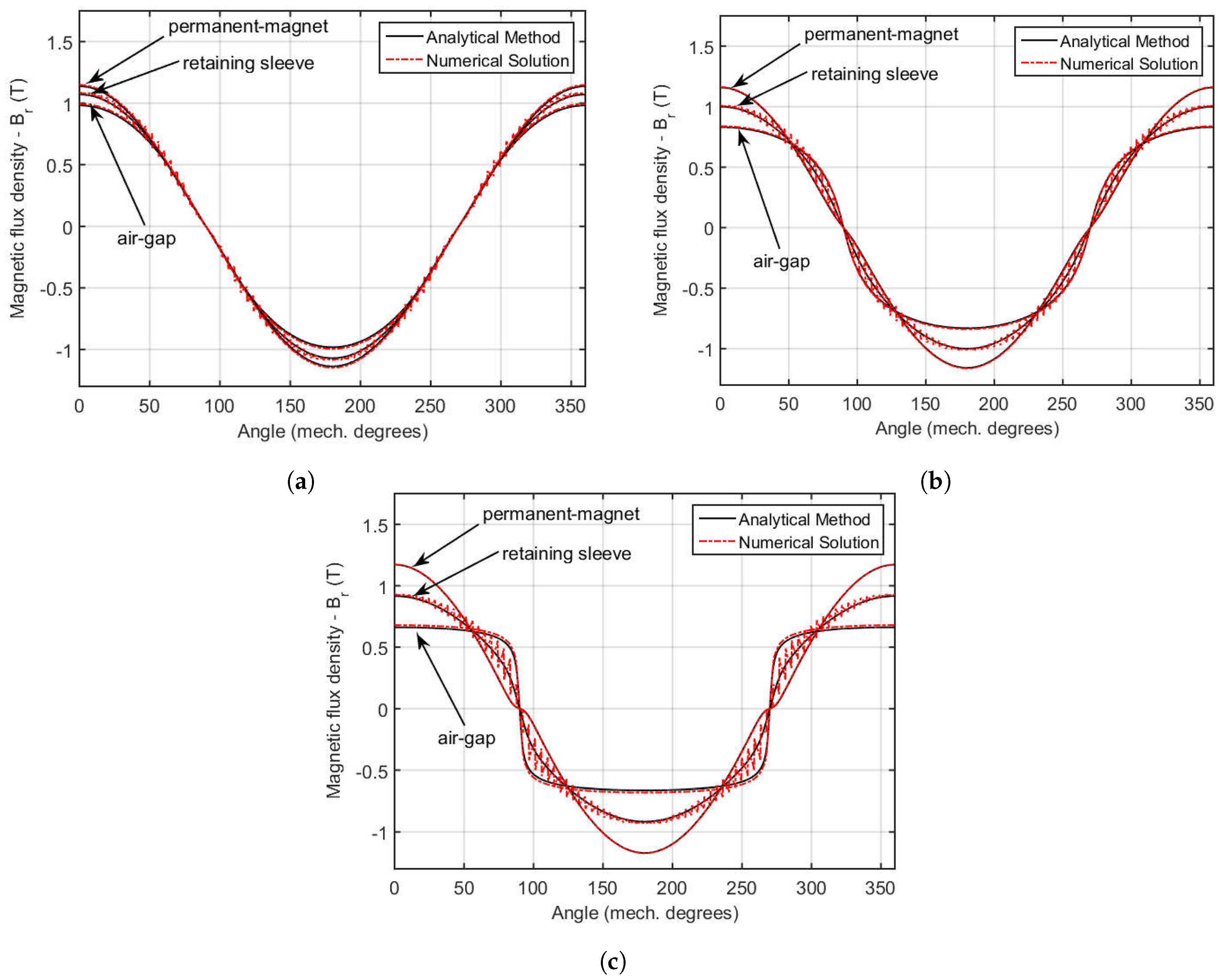
The mathematical formulation presented in this section is general and can be applied to several PM machine configurations. However, to help illustrate the proposed methodology and to show the importance of evaluating the RS saturation, the following sections will discuss its application to a HS machine prototype.

3. Evaluated Prototype

The machine used for verifying the proposed methodology is part of a micro-compressed air energy storage (micro-CAES) system [37]. It was built from a conventional turbocharger system adapted to operate only with air [37]. Due to its high speeds, the power density is considerably higher. It is suitable for small scale applications, such as operating with distributed generation to improve power supply reliability. The prototype is illustrated in Figure 2, where Figure 2a shows the dissembled system, and Figure 2b illustrates the mounted system.
In such application, generator design is carried out based on some overall restrictions, such as reduced size and cost. A single high-speed shaft eliminates the need of gear-box, thus improving system reliability [2]. However, a high-speed drive system design is critical, with difficulties associated with generator topology, material selection, manufacturing procedure, bearings types and many others. All of these concerns for the evaluated machine are addressed by Maia et al. [37].
The constructed machine consists of a two-pole surface-mounted PM generator with parallel magnetization. In order to fulfill the banding requirement, a stainless steel AISI 310 sleeve was adopted for its additional properties. The high electrical conductivity is expected to help shielding the magnets and rotor iron from high-frequency magnetic fields [3], thus reducing rotor losses. Moreover, behaving like a damper winding, it could help improving transient stability. The stator, manufactured with electric steel with 0.35 mm lamination thickness, was designed with full-pitch concentrated winding, as pictured in Figure 3a. The assembled prototype is presented in Figure 3b and final machine characteristics are shown in Table 2.
Maia et al. [37,38] successfully evaluated the electromechanical design of a HS generator directly driven by a micro-CAES system. Additionally, experimental measurements carried out helped reevaluate the assumptions usually made to simplify the mathematical formulation. Using flux sensing coils, as indicated in Figure 3a, measurements pointed that the RS had higher magnetic permeability than expected from the material specification. The RS machining, needed to achieve proper mechanical tolerances, changed the relative permeability to approximately 300. With the adjusted values, numerical simulations using FEMM [39] were performed. The results, compared with measurements, are presented in Figure 4.
Discarding any saturation effects in the RS region, the higher relative permeability increases the pole-to-pole leakage flux, reducing significantly the no-load stator flux linkage and electromotive force [5]. Experimental no-load measurements did not match the results from FEM simulations which assumed linear RS relative permeability. Reevaluating the numerical simulation with nonlinear relative permeability for the RS region yields accurate results compared with measurements, as illustrated in Figure 5. The saturated RS provides a preferential path for the magnetic flux in the magnetization axis, diminishing the pole-to-pole leakage flux. The saturation curve for the stainless-steel RS was based on [40] and adjusted to provide the unsaturated relative permeability of approximately 300. The relative permeability profile in the RS for the PM generator at no-load condition is illustrated in Figure 6.
Another aspect observed from the manufactured system is that, though not measured, cogging torque was perceived by manually rotating the machine shaft. This is an interesting result because it also leads to the assumption that saturation was taking place in the RS. A linear magnetic parameter, with this type of PM excitation and slot geometry, would result in a constant torque, without any harmonic content.
The interaction between magnetic flux produced by the PM and the stator non-uniform structure governs the cogging torque phenomenon [29]. This relationship can be clearly visualized through the complex permeance modeling method [8,13,41,42]. From closed form solutions for calculating the cogging torque using conformal mapping [41], no cogging torque would be expected for the studied motor. The rotor was manufactured with a two-pole NdFeB ring shaped with parallel magnetization, which produces a sinusoidal air-gap magnetic flux density with no space harmonic content, and the slotting configuration results in a constant torque profile, with no oscillation. Using the revised relative permeability for the RS, simulations using FEMM [39] were performed to illustrate the effect of saturation in the cogging torque.
To allow the evaluation of the stator core saturation effect on the cogging torque, the simulation was made using different remanence values for the PM. Figure 7a,b illustrate the results for different remanence values, B ^ r e m = 1.2 T and B ^ r e m = 1.3 T, respectively. For each PM remanent magnetization value, simulation evaluated effects of using linear or nonlinear permeability of RS, stator and rotor core.

4. Application Example Results and Validation

The validation was supported by problems simplification. Machine slotting effect was neglected and many magnetic parameters were approximated, as discussed in Section 2. This approach was chosen to help clarify some key aspects in the new formulation proposed. Furthermore, the relative permeability was defined only with a constant and one fundamental space-varying component, i.e., μ r ( φ ) = μ ^ r , 0 + μ ^ r , 1 cos 2 φ r . This approximation is justified here to help evaluate the interaction between space harmonic of different orders, showing that even low order spatial harmonics in the RS can significantly affect the air-gap density flux distribution. In addition, results from the analytical method were validated from FEM results.
The geometrical parameters used in the mathematical formulation are based on the PM machine structure illustrated in Figure 1 with values given in Table 3. The rotor type allows one more simplification without loss of generality. The rotor iron core region was neglected and the rotor structure is composed of full cylindrical PM and the RS, as illustrated in Figure 8. This reduces one boundary condition and, as a consequence, one linear equation (i.e., D k ( 1 ) = 0 , from (3b)). In addition, the machine PM configuration simplifies the Poisson’s equation since the curl of the parallel magnetization vector is null. Therefore, the radial and tangential components of the magnetization were defined only with a fundamental space harmonic, i.e., B r e m = B ^ r e m cos φ r a r B ^ r e m sin φ r a φ , where a r and a φ are the unit vectors in the radial and tangential direction.
Combining Equations (3a) and (3b) with the boundary conditions (4) and (5) establishes a set of linear equations. However, the RS boundary conditions were reevaluated with the procedure developed in Section 2. First, for the studied machine with only fundamental magnetization vector, the index l in (13) is set as equal to one. Table 4 presents the space harmonic indexes m and n, as defined in (12), which satisfies the conditions in Table 1. In addition, the superscripts in Table 4 relate the conditions in Table 1 that are satisfied.
With the presented space harmonic indexes combinations, the system of linear equations can be defined. First, three boundary conditions used to derive the linear equation system remain unchanged. For the normal flux density continuity at r = r m and r = r s l and for the tangential field intensity at r = r s , the expressions can be derived for any space harmonic indexes as follows:
r s k 1 C k ( 3 ) r s k 1 D k ( 3 ) = 0 ,
r s l k 1 C k ( 3 ) + r s l k 1 D k ( 3 ) r s l k 1 C k ( 2 ) r s l k 1 D k ( 2 ) = 0 ,
r m k 1 C k ( 2 ) + r m k 1 D k ( 2 ) r m k 1 C k ( 1 ) = 0 .
Furthermore, from the space harmonic relations defined in Table 4, the tangential field intensity continuity at r = r m and r = r s l can be expressed as
  • For k = 1 :
    μ ^ r , 0 1 2 μ ^ r , 1 C 1 ( 3 ) μ ^ r , 0 1 2 μ ^ r , 1 r s l 2 D 1 ( 3 ) C 1 ( 2 ) + r s l 2 D 1 ( 2 ) + 3 2 μ ^ r , 1 r s l 2 C 3 ( 3 ) 3 2 μ ^ r , 1 r s l 4 D 3 ( 3 ) ,
    C 1 ( 2 ) r m 2 D 1 ( 2 ) μ ^ r , 0 1 2 μ ^ r , 1 C 1 ( 1 ) 3 2 μ ^ r , 1 r m 2 C 3 ( 1 ) = μ ^ r , 0 1 2 μ ^ r , 1 B ^ r e m .
  • For k = 3 :
    1 6 μ ^ r , 1 C 1 ( 3 ) 1 6 μ ^ r , 1 r s l 2 D 1 ( 3 ) + μ ^ r , 0 r s l 2 C 3 ( 3 ) μ ^ r , 0 r s l 4 D 3 ( 3 ) r s l 2 C 3 ( 2 ) + r s l 4 D 3 ( 2 ) + 5 6 μ ^ r , 1 r s l 4 C 5 ( 3 ) 5 6 μ ^ r , 1 r s l 6 D 5 ( 3 ) = 0 ,
    1 6 μ ^ r , 1 C 1 ( 1 ) + r m 2 C 3 ( 2 ) r m 4 D 3 ( 2 ) μ ^ r , 0 r m 2 C 3 ( 1 ) 5 6 μ ^ r , 1 r m 4 C 5 ( 1 ) = 1 6 μ ^ r , 1 B ^ r e m .
  • For k 5 :
    k 2 2 k μ ^ r , 1 r s l k 3 C k 2 ( 3 ) k 2 2 k μ ^ r , 1 r s l k + 1 D k 2 ( 3 ) + μ ^ r , 0 r s l k 1 C k ( 3 ) μ ^ r , 0 r s l k 1 D k ( 3 ) r s l k 1 C k ( 2 ) + r s l k 1 C k ( 2 ) + k + 2 2 k μ ^ r , 1 r s l k + 1 C k + 2 ( 3 ) k + 2 2 k μ ^ r , 1 r s l k 3 D k + 2 ( 3 ) = 0 ,
    k 2 2 k μ ^ r , 1 r m k 3 C k 2 ( 1 ) + r m k 1 C k ( 2 ) r m k 1 D k ( 2 ) μ ^ r , 0 r m k 1 C k ( 1 ) k + 2 2 k μ ^ r , 1 r m k + 1 C k + 2 ( 1 ) = 0 .
The proposed formulation requires different space harmonics orders to be solved integrally, which differs from the usual procedure. In addition, the analytical method was validated based on results from numerical simulations. The FEM analysis was set with the same premises used in the analytical model. For the space-varying relative permeability in the RS, the region was discretized. To obtain the needed accuracy, 80 regions were defined to characterize this space-varying parameter in the RS, as illustrated in Figure 8.
The simulations were carried out with several values for the RS relative permeability, considering both homogeneous and space-varying parameter. Table 5 summarizes the obtained result where the RS was modeled based on the evaluated PM machine. The results show the radial component of the magnetic flux density in the air-gap. Moreover, to illustrate the analytical model application with different permeability values, the model validation was done with similar parameters but with different magnitude orders, as illustrated in Figure 9 with the results presented in Table 6 and Table 7.
The results show a very good agreement with those obtained from the FEM simulations. As expected from the derived equations, the results show great interaction among space harmonics of different orders. Table 5, Table 6 and Table 7 present the results with different harmonic spectrum considered for the analytical method, ranging from k = 1 to k m a x . In addition, the results are illustrated in Figure 10, which depicts the magnetic flux density waveforms from both methods in different regions (viz., the average radius of the air-gap, RS and PM). In these figures, results are for a maximum number of harmonics equal to k m a x = 100 .
As can be appreciated from the results in Table 5, Table 6 and Table 7, the analyital method accuracy is dependent on the maximum order of space harmonics, i.e., k m a x . For a higher relative permeability case presented in Table 6 and in Figure 10c, the analytical method converged (with an error smaller than 5 % ) only for space harmonic content evaluated up to the thirtieth order. In addition, the relative permeability evaluated with only one harmonic content leads to a air-gap magnetic flux density with significant spacial harmonic content.
Furthermore, if only the fundamental component would exist in a system, with μ r , 1 = 0 in the evaluated PM machine, no harmonic content would be observed using either techniques, FEM or analytical method. This result is expected since the PM topology with parallel magnetization would result in only fundamental magnetic fields. In addition, as expected from the no-load voltage measurements in the prototype in comparison with numerical results, higher relative permeability in the RS region increases the pole-to-pole leakage flux significantly. This behavior would diminish air-gap magnetic fields and stator linkage flux if no saturation effect took place in the RS. Therefore, the space-varying relative permeability helps to maintain the magnetization level.

5. Conclusions

In this work, a new analytical model is presented that incorporates non-homogeneous magnetic parameters. The novel procedure evaluates an annular region defined with a space-varying relative permeability, where iterative methods could be used to study saturation phenomenon. This new solution is needed because experimental analysis pointed out a higher order space harmonics spectrum for the calculated magnetic field. In the assessed PM machine, linear models provide only fundamental components of the magnetic fields. Such assumption would lead to erroneous conclusions.
The novel analytical method was validated with results obtained from finite-element analysis. Seeking a clearer and direct way to analyze the derived results, the PM machine model and parameters not related to the proposed solution were simplified. In this case, linear system equations were derived illustrating the proposed methodology. Comparison with numerical solutions for magnetic flux density at different PM machine regions showed very good agreement for both amplitude and phase.
The proposed technique is derived from well-established analytical solution methodology, where other researched improvements can be extended with it. For example, evaluation of slotting effect can be easily carried out with a subdomain model. This will help suppress known analytical method drawbacks, such as the need to define linear material properties to solve the problem. Thus, improved accuracy in magnetic field calculation, aligned with fast computation time, can extend analytical method application capabilities throughout PM machine and drive design procedures.

Author Contributions

Supervision, B.J.C.F.; Writing—original draft, G.A.M.; Writing—review & editing, T.A.C.M.

Acknowledgments

This study was financed in part by the Coordenação de Aperfeiçoamento de Pessoal de Nível Superior - Brasil (CAPES) - Finance Code 001, the Conselho Nacional de Desenvolvimento Científico e Tecnológico (CNPq) and the Universidade Federal de Minas Gerais (UFMG).

Conflicts of Interest

The authors declare no conflict of interest.

References

  1. Luise, F.; Tessarolo, A.; Pieri, S.; Raffin, P.; Chiara, M.D.; Agnolet, F.; Scalabrin, M. Design and technology solutions for high-efficiency high-speed motors. In Proceedings of the 2012 XXth International Conference on Electrical Machines, Marseille, France, 2–5 September 2012; pp. 157–163. [Google Scholar]
  2. Borisavljević, A. Limits, Modeling and Design of High-Speed Permanent Magnet Machines. Ph.D. Thesis, Delft University of Technology, Delft, The Netherlands, 2011. [Google Scholar]
  3. Holm, S.R. Modelling and Optimization of a Permanent Magnet Machine in a Flywheel. Ph.D. Thesis, Delft University of Technology, Delft, The Netherlands, 2003. [Google Scholar]
  4. Roubache, L.; Boughrara, K.; Dubas, F.; Ibtiouen, R. New Subdomain Technique for Electromagnetic Performances Calculation in Radial-Flux Electrical Machines Considering Finite Soft-Magnetic Material Permeability. IEEE Trans. Magn. 2018, 54, 1–15. [Google Scholar] [CrossRef]
  5. Qiu, H.; Duan, Q.; Yao, L.; Dong, Y.; Yi, R.; Cui, G.; Li, W. Analytical analysis of sleeve permeability for output performance of high speed permanent magnet generators driven by micro gas turbines. Appl. Math. Model. 2016, 40, 9017–9028. [Google Scholar] [CrossRef]
  6. Polinder, H. On the Losses in a High-Speed Permanent-Magnet Generator with Rectifier. Ph.D. Thesis, Delft University of Technology, Delft, The Netherlands, 1998. [Google Scholar]
  7. Boubaker, N.; Matt, D.; Enrici, P.; Nierlich, F.; Durand, G.; Orlandini, F.; Longère, X.; Aïgba, J. Study of eddy-current loss in the sleeves and Sm-Co magnets of a high-performance SMPM synchronous machine (10 kRPM, 60 kW). Electr. Power Syst. Res. 2017, 142, 20–28. [Google Scholar] [CrossRef]
  8. Willerich, S.; Herzog, H.G. Prediction of the magnetic field in the air-gap of synchronous machines on a preliminary design level—Machine modelling and field calculation. In Proceedings of the 2015 IEEE International Electric Machines Drives Conference (IEMDC), Coeur d’Alene, ID, USA, 10–13 May 2015; pp. 1292–1298. [Google Scholar]
  9. Holm, S.R.; Polinder, H.; Ferreira, J.A. Analytical Modeling of a Permanent-Magnet Synchronous Machine in a Flywheel. IEEE Trans. Magn. 2007, 43, 1955–1967. [Google Scholar] [CrossRef] [Green Version]
  10. Zhu, Z.Q.; Howe, D.; Bolte, E.; Ackermann, B. Instantaneous magnetic field distribution in brushless permanent magnet DC motors. I. Open-circuit field. IEEE Trans. Magn. 1993, 29, 124–135. [Google Scholar] [CrossRef]
  11. Ackermann, B.; Sottek, R. Analytical modeling of the cogging torque in permanent magnet motors. Electr. Eng. 1995, 78, 117–125. [Google Scholar] [CrossRef]
  12. Boules, N. Prediction of No-Load Flux Density Distribution in Permanent Magnet Machines. IEEE Trans. Ind. Appl. 1985, IA-21, 633–643. [Google Scholar] [CrossRef]
  13. Ramakrishnan, K.; Curti, M.; Zarko, D.; Mastinu, G.; Paulides, J.J.H.; Lomonova, E.A. Comparative analysis of various methods for modelling surface permanent magnet machines. IET Electr. Power Appl. 2017, 11, 540–547. [Google Scholar] [CrossRef]
  14. Hanic, A.; Zarko, D.; Kuhinek, D.; Hanic, Z. On-Load Analysis of Saturated Surface Permanent Magnet Machines Using Conformal Mapping and Magnetic Equivalent Circuits. IEEE Trans. Energy Convers. 2018, 33, 915–924. [Google Scholar] [CrossRef]
  15. Shin, K.H.; Park, H.I.; Cho, H.W.; Choi, J.Y. Analytical prediction for electromagnetic performance of interior permanent magnet machines based on subdomain model. AIP Adv. 2017, 7, 056669. [Google Scholar] [CrossRef] [Green Version]
  16. Tikellaline, A.; Boughrara, K.; Takorabet, N. Magnetic field analysis of double excited synchronous motor using numerical conformal mapping. In Proceedings of the 2017 5th International Conference on Electrical Engineering-Boumerdes (ICEE-B), Boumerdes, Algeria, 29–31 October 2017; pp. 1–6. [Google Scholar]
  17. Ramakrishnan, K.; Zarko, D.; Hanic, A.; Mastinu, G. Improved method for field analysis of surface permanent magnet machines using Schwarz-Christoffel transformation. IET Electr. Power Appl. 2017, 11, 1067–1075. [Google Scholar] [CrossRef]
  18. Hannon, B.; Sergeant, P.; Dupré, L. Study of the Effect of a Shielding Cylinder on the Torque in a Permanent-Magnet Synchronous Machine Considering Two Torque-Producing Mechanisms. IEEE Trans. Magn. 2017, 53, 1–8. [Google Scholar] [CrossRef] [Green Version]
  19. Djelloul-Khedda, Z.; Boughrara, K.; Dubas, F.; Ibtiouen, R. Nonlinear Analytical Prediction of Magnetic Field and Electromagnetic Performances in Switched Reluctance Machines. IEEE Trans. Magn. 2017, 53, 1–11. [Google Scholar] [CrossRef]
  20. Djelloul-Khedda, Z.; Boughrara, K.; Dubas, F.; Kechroud, A.; Souleyman, B. Semi-Analytical Magnetic Field Predicting in Many Structures of Permanent-Magnet Synchronous Machines Considering the Iron Permeability. IEEE Trans. Magn. 2018, 54, 1–21. [Google Scholar] [CrossRef]
  21. Ben Yahia, M.; Boughrara, K.; Dubas, F.; Roubache, L.; Ibtiouen, R. Two-Dimensional Exact Subdomain Technique of Switched Reluctance Machines with Sinusoidal Current Excitation. Math. Comput. Appl. 2018, 23, 59. [Google Scholar]
  22. Boughrara, K.; Dubas, F.; Ibtiouen, R. 2-D Exact Analytical Method for Steady-State Heat Transfer Prediction in Rotating Electrical Machines. IEEE Trans. Magn. 2018, 54, 1–19. [Google Scholar] [CrossRef]
  23. Dubas, F.; Boughrara, K. New Scientific Contribution on the 2-D Subdomain Technique in Cartesian Coordinates: Taking into Account of Iron Parts. Math. Comput. Appl. 2017, 22, 17. [Google Scholar] [CrossRef]
  24. Dubas, F.; Boughrara, K. New Scientific Contribution on the 2-D Subdomain Technique in Polar Coordinates: Taking into Account of Iron Parts. Math. Comput. Appl. 2017, 22, 42. [Google Scholar] [CrossRef]
  25. Tiegna, H.; Amara, Y.; Barakat, G. Overview of analytical models of permanent magnet electrical machines for analysis and design purposes. Math. Comput. Simul. 2013, 90, 162–177. [Google Scholar] [CrossRef]
  26. Abbaszadeh, K.; Alam, F.R. On-Load Field Component Separation in Surface-Mounted Permanent-Magnet Motors Using an Improved Conformal Mapping Method. IEEE Trans. Magn. 2016, 52, 1–12. [Google Scholar] [CrossRef]
  27. Alam, F.R.; Abbaszadeh, K. Magnetic Field Analysis in Eccentric Surface-Mounted Permanent-Magnet Motors Using an Improved Conformal Mapping Method. IEEE Trans. Energy Convers. 2016, 31, 333–344. [Google Scholar] [CrossRef]
  28. Oner, Y.; Zhu, Z.Q.; Wu, L.J.; Ge, X.; Zhan, H.; Chen, J.T. Analytical On-Load Subdomain Field Model of Permanent-Magnet Vernier Machines. IEEE Trans. Ind. Electr. 2016, 63, 4105–4117. [Google Scholar] [CrossRef]
  29. Qian, H.; Guo, H.; Wu, Z.; Ding, X. Analytical Solution for Cogging Torque in Surface-Mounted Permanent-Magnet Motors With Magnet Imperfections and Rotor Eccentricity. IEEE Trans. Magn. 2014, 50, 1–15. [Google Scholar] [CrossRef]
  30. Chebak, A.; Viarouge, P.; Cros, J. Improved Analytical Model for Predicting the Magnetic Field Distribution in High-Speed Slotless Permanent-Magnet Machines. IEEE Trans. Magn. 2015, 51, 1–4. [Google Scholar] [CrossRef]
  31. Rahideh, A.; Korakianitis, T. Analytical calculation of open-circuit magnetic field distribution of slotless brushless PM machines. Int. J. Electr. Power Energy Syst. 2013, 44, 99–114. [Google Scholar] [CrossRef]
  32. Ortega, A.J.P.; Paul, S.; Islam, R.; Xu, L. Analytical Model for Predicting Effects of Manufacturing Variations on Cogging Torque in Surface-Mounted Permanent Magnet Motors. IEEE Trans. Ind. Appl. 2016, 52, 3050–3061. [Google Scholar] [CrossRef]
  33. Sprangers, R.L.J.; Paulides, J.J.H.; Gysen, B.L.J.; Lomonova, E.A. Magnetic Saturation in Semi-Analytical Harmonic Modeling for Electric Machine Analysis. IEEE Trans. Magn. 2016, 52, 1–10. [Google Scholar] [CrossRef]
  34. Hannon, B.; Sergeant, P.; Dupré, L. Two-dimensional fourier-based modeling of electric machines. In Proceedings of the 2017 IEEE International Electric Machines and Drives Conference (IEMDC), Miami, FL, USA, 21–24 May 2017; pp. 1–8. [Google Scholar]
  35. Pfister, P.; Yin, X.; Fang, Y. Slotted Permanent-Magnet Machines: General Analytical Model of Magnetic Fields, Torque, Eddy Currents, and Permanent-Magnet Power Losses Including the Diffusion Effect. IEEE Trans. Magn. 2016, 52, 1–13. [Google Scholar] [CrossRef]
  36. Dubas, F.; Espanet, C. Analytical Solution of the Magnetic Field in Permanent-Magnet Motors Taking Into Account Slotting Effect: No-Load Vector Potential and Flux Density Calculation. IEEE Trans. Magn. 2009, 45, 2097–2109. [Google Scholar] [CrossRef]
  37. Maia, T.A.; Faria, O.A.; Barros, J.E.; Porto, M.P.; Filho, B.J.C. Test and simulation of an electric generator driven by a micro-turbine. Electr. Power Syst. Res. 2017, 147, 224–232. [Google Scholar] [CrossRef]
  38. Maia, T.A.; Barros, J.E.; Filho, B.J.C.; Porto, M.P. Experimental performance of a low cost micro-CAES generation system. Appl. Energy 2016, 182, 358–364. [Google Scholar] [CrossRef]
  39. Meeker, D. Finite Element Method Magnetics v4.2; 2015. Available online: www.femm.info/wiki/HomePage (accessed on 9 November 2018).
  40. Fofanov, D.; Riedner, S. Magnetic Properties of Stainless Steels: Applications, Opportunities and New Developments. In Proceedings of the 2011 World Stainless Steel Conference & Expo, Maastricht, The Netherlands, 29 November–1 December 2011; pp. 1–13. [Google Scholar]
  41. Zarko, D.; Ban, D.; Lipo, T.A. Analytical Solution for Cogging Torque in Surface Permanent-Magnet Motors Using Conformal Mapping. IEEE Trans. Magn. 2008, 44, 52–65. [Google Scholar] [CrossRef]
  42. Zarko, D.; Ban, D.; Lipo, T.A. Analytical calculation of magnetic field distribution in the slotted air gap of a surface permanent-magnet motor using complex relative air-gap permeance. IEEE Trans. Magn. 2006, 42, 1828–1837. [Google Scholar] [CrossRef]
Figure 1. A quarter cross section of PM synchronous machine for analytical calculation.
Mca 23 00072 g001
Figure 2. Low cost high-speed micro-CAES system: (a) disassembled components; and (b) system in operation [37].
Mca 23 00072 g002
Figure 3. PM generator: (a) schematic view; and (b) assembled prototype stator.
Mca 23 00072 g003
Figure 4. Measured and simulated results for induced voltage in exploring coils.
Mca 23 00072 g004
Figure 5. Measured and simulated results for no-load voltage.
Mca 23 00072 g005
Figure 6. RS space-varying relative permeability profile.
Mca 23 00072 g006
Figure 7. Cogging torque FEMM simulation with: (a) B ^ r e m = 1.2 T; and (b) B ^ r e m = 1.3 T.
Mca 23 00072 g007
Figure 8. A quarter cross section of the PM synchronous machine with a segmented RS region for FEMM simulation.
Mca 23 00072 g008
Figure 9. Different relative permeability profile for method validation.
Mca 23 00072 g009
Figure 10. Analytical and numarical simulation comparison at different regions: (a) μ r = 16 + 15 cos ( 2 φ r ) ; (b) μ r = 151 + 150 cos ( 2 φ r ) ; and (c) μ r = 1501 + 1500 cos ( 2 φ r ) .
Mca 23 00072 g010
Table 1. Space harmonic index relations for non-zero integral solutions.
ConditionIndex RelationIntegral Result
1 k n 2 m = 0 π 2
2 k n + 2 m = 0 π 2
3 k + n 2 m = 0 π 2
Table 2. Prototype PM machine characteristics.
ParametersValue
Induced voltage 220 V R M S
Rated speed70,000 RPM
Rated current9.2 A
Rated power3.5 kW
Stator length100 mm
PM diameter21 mm
Table 3. Parameters for analytical model of slotless geometry.
ParametersSymbolValue
Radius of magnet surface r m 9.8935 mm
Radius of retaining sleeve surface r s l 10.475 mm
Radius of stator inner surface r s 11.0 mm
Magnet remanence B ^ r e m 1.2 T
Table 4. Space harmonic index relation for an evaluated PM machine.
Base IndexRelative Permeability Index
m = 0 m = 1
k = 1 n 1 , 2 = k n 2 = 3 ; n 3 = 1
k = 3 n 1 = 1 ; n 2 = 5
k = 5 n 1 = 3 ; n 2 = 7
k = 7 n 1 = 5 ; n 2 = 9
Table 5. Simulation result for B ^ r , k ( 3 ) ( T ) : relative permeability based on measurements.
HarmonicRelative Permeability Model
μ r = 300 μ r = 151 + 150 cos ( 2 φ r )
FEMAnalyticalFEMAnalyticalAnalyticalAnalytical
k max = 3 k max = 7 k max = 13
k = 1 0.584 0.585 0.957 0.932 0.948 0.948
k = 3 00 0.160 0.118 0.151 0.156
k = 5 00 0.060 0.050 0.058
k = 7 00 0.029 0.017 0.028
Table 6. Simulation result for B ^ r , k ( 3 ) ( T ) : relative permeability based on measurements.
HarmonicRelative Permeability Model
μ r = 3000 μ r = 1501 + 1500 cos ( 2 φ r )
FEMAnalyticalFEMAnalyticalAnalyticalAnalytical
k max = 3 k max = 15 k max = 31
k = 1 0.117 0.117 0.843 0.518 0.759 0.803
k = 3 00 0.245 0.084 0.204 0.227
k = 5 00 0.134 0.101 0.120
k = 7 00 0.088 0.059 0.076
Table 7. Simulation result for B ^ r , k ( 3 ) ( T ) : relative permeability based on measurements.
HarmonicRelative Permeability Model
μ r = 30 μ r = 16 + 15 cos ( 2 φ r )
FEMAnalyticalFEMAnalyticalAnalyticalAnalytical
k max = 3 k max = 7 k max = 13
k = 1 0.972 0.972 1.030 1.019 1.015 1.014
k = 3 00 0.036 0.037 0.034 0.033
k = 5 00 0.001 0.002 0.000
k = 7 00 0.004 0.000 0.002

