Article

Application of Approximate Analytical Technique Using the Homotopy Perturbation Method to Study the Inclination Effect on the Thermal Behavior of Porous Fin Heat Sink

1
School of Electrical Engineering, Faculty of Engineering and Informatics, University of Bradford, Bradford BD7 1DP, UK
2
Department of Mechanical Engineering, University of Lagos, 101017 Akoka, Nigeria
*
Author to whom correspondence should be addressed.
Math. Comput. Appl. 2018, 23(4), 62; https://doi.org/10.3390/mca23040062
Submission received: 19 September 2018 / Revised: 11 October 2018 / Accepted: 12 October 2018 / Published: 15 October 2018
(This article belongs to the Section Engineering)

Abstract

:
This article presents the homotopy perturbation method (HPM) employed to investigate the effects of inclination on the thermal behavior of a porous fin heat sink. The study aims to review the thermal characterization of heat sink with the inclined porous fin of rectangular geometry. The study establishes that heat sink of an inclined porous fin shows a higher thermal performance compared to a heat sink of equal dimension with a vertical porous fin. In addition, the study also shows that the performance of inclined or tilted fin increases with decrease in length–thickness aspect ratio. The study further reveals that increase in the internal heat generation variable decreases the fin temperature gradient, which invariably decreases the heat transfer of the fin. The obtained results using HPM highlights the accuracy of the present method for the analysis of nonlinear heat transfer problems, as it agrees well with the established results of Runge–Kutta.

1. Introduction

With the increasing demand for high-performance electronic systems of miniaturized packaging, electronic cooling, and subsequently, the thermal enhancement of heat transfer components is rapidly gaining more attention. To achieve miniaturized packaging, the challenge to trade off size with efficiency often comes at a design cost. One key design consideration is the issue of excess heat building up within the thermal components, which could lead to the eventual damage of the electronic circuitry and overall functional breakdown of such electronic systems.
A key approach to achieve compact, thermally efficient electronic systems is to effectively improve heat dissipation between the device surface and the surrounding environment using extended surface or fin. Fin application is identified as a viable approach for enhancing thermal performance of different systems following the research breakthrough of [1]. Consequently, research on heat transfer using porous fin has become one of the emerging research areas for engineers and scientists, since, for the same weight, porous fin is established to show better performance than solid fins of equal dimension [2,3].
Different authors have applied different methods including analytical, numerical, and hybrid; i.e. a combination of two or more methods to investigate the thermal behaviour of fin under different operating conditions. Example of these methods include: Runge–Kutta [4,5,6], Galerkin’s method of weighted residual [7,8], least squares method [9], and various collocation methods, including Haar wavelet [10,11], spectral [12], Chebychev [13,14,15], spectral element [16], Legendre [17], Adomian decomposition method [18,19], differential transform method [20,21,22], variational iteration method [23], homotopy analysis method [24], and hybrid methods [25,26,27].
Furthermore, in the quest to enhance the performance of fins, especially porous fins, different authors are investigating various thermal characteristics of porous fin including material, geometry, orientation, and composition are investigated to achieve heat transfer enhancement and augmentation. Since the heat sink is a critical component of most electronic systems, several authors have carried out different investigations on how the orientation of the heat sink as a composite unit affects its overall thermal performance [28,29]. Nevertheless, to the best of our knowledge, a study on the effect of inclination on the thermal performance of solid or porous fin heat sinks have not been carried out in the literature.
In this article, the homotopy perturbation method (HPM) is applied to theoretically investigate the effect of inclination and internal heat generation on the thermal behavior of a porous fin heat sink. HPM is an efficient approximate analytical approach useful for boundary value problems as shown in the present work and is independent on a small parameter in the governing equation. Furthermore, HPM handles the conditions at the boundaries without necessarily representing them, thereby obtaining the solution at every point without the presence of an unknown. The study aims at thermal characterization of heat sink with inclined porous fins of rectangular geometry. The rest of the article is organised as follows: The physical model of the process will be presented in Section 2. In Section 3, the developed nonlinear governing equation is solved using HPM. The parametric results of the study are discussed in Section 4. The summarized conclusions from the analysis are presented in Section 5.

2. Problem Formulation

Figure 1 shows a heat sink of vertical fins. The geometry of the porous fin is of the length L, thickness t and is exposed on both faces to a convective–radiative environment at temperature T. To simplify the formulation of fin problem, we made the following assumptions:
  • Porous media is homogeneous and saturated with single-phase fluid.
  • The interaction between the saturated fluid and medium is governed by Darcy’s model.
  • Thermo-physical characteristics of the porous fin with that of the fluid are constant.
  • Fin tip is adiabatic.
The steady-state one-dimensional thermal model of a single porous fin heat sink is established from our previous works [8,11,15,30] is expressed as:
d 2 T d x 2 ρ c p g K β t h k e f f t v ( T T a ) 2 h e f f k e f f t ( T T a ) + q ( T ) k e f f A c r = 0
The boundary conditions are
x = 0 ,   d T d x = 0 x = L ,   T = T b
where the temperature-dependent internal heat generation is given as:
q ( T ) = q 0 [ 1 + λ ( T T ) ]
If we substitute Equation (3) into Equation (1), we arrive at
d 2 T d x 2 ρ c p g K β t h k e f f t v ( T T a ) 2 h e f f k e f f t ( T T a ) + q o k e f f A c r [ 1 + λ ( T T ) ] = 0
The effective convective heat transfer coefficient ( h e f f = ( k N u ) / L ) is found from the correlations
N u = { 0.68 + 0.67 [ ( G r c o s β ) P r ] 0.25 { 1 + ( 0.492 P r ) 0.5625 } 0.444 ( G r c o s β ) P r < 10 4 0.59 [ ( G r c o s β ) P r ] 0.25 10 4 < ( G r c o s β ) P r < 10 9
Alternatively, for all values of ( G r ( c o s β ) ) P r
N u = { 0.825 + 0.387 [ ( G r c o s β ) P r ] 0.167 { 1 + ( 0.492 P r ) 0.5625 } 0.296 } 2
where the inclination angle is expressed as “β” which is “0” for the vertical fin.
On introducing the dimensionless parameters in Equation (7) into Equation (4)
X = x L ,   θ = T T a T b T a ,   S h = ρ c p g k β t h L 2 ( T b T a ) t v k e f f ,   M 2 = h e f f L 2 k e f f t ,   Q = q 0 L 2 t k e f f A e f f ( T b T a ) ,   γ = λ ( T b T a )
We arrive at
d 2 θ d X 2 S h θ 2 M a 2 θ + M 2 Q ( 1 + γ θ ) = 0
Therefore, Equation (8) becomes the nonlinear dimensionless thermal model, and the dimensionless boundary condition becomes
X = 0 ,   d θ d X = 0 X = 1 ,   θ = 1

3. Method of Solution using HPM

The dimensionless nonlinear thermal equation of Equation (8) is solved using HPM. Therefore, to solve the present problem, a homotopy construction for Equation (8) is generated as:
H ( θ , p ) = ( 1 p ) [ d 2 θ d X 2 ] + p [ d 2 θ d X 2 S h θ 2 M 2 θ + M 2 Q ( 1 + γ θ ) ]
Here p [ 0 , 1 ] is an embedding parameter, and for p = 0 and p = 1 , we have
θ ( X , 0 ) = θ 0 ( X ) ,   θ ( X , 1 ) = θ 1 ( X )
It is worth noting that as p increases from 0 to 1, θ ( X , p ) changes from θ 0 ( X ) to θ 1 ( X ) .
Assume the solution of Equation (8) is expressed as a series in p as:
θ ( X ) = θ 0 ( X ) + p θ 1 ( X ) + p 2 θ 2 ( X ) + p 3 θ 2 ( X ) + = i = 0 n p i θ i ( X )
Then by substituting Equation (12) into Equation (10) and expanding the equation while terms of the same order of p are collected together, the resulting expression will appear in form of a polynomial in p . Moreover, by equating the coefficients of the polynomial in p to zero, we derive a set of differential equations and their corresponding boundary conditions as
p 0 :   d 2 θ 0 d X 2 ( X ) = 0 ,   θ 0 ( 0 ) = 1   θ 0 ( 1 ) = 0
p 1 :   d 2 θ 1 d X 2 + M 2 Q γ θ 0 S h θ 0 2 M 2 θ 0 + M 2 Q = 0 ,   θ 1 ( 0 ) = 0   θ 1 ( 1 ) = 0
p 2 :   d 2 θ 2 d X 2 + M 2 Q γ θ 1 S h θ 0 θ 1 M 2 θ 1 = 0 ,   θ 2 ( 0 ) = 0   θ 2 ( 1 ) = 0
p 3 :   d 2 θ 3 d X 2 + M 2 Q γ θ 2 S h θ 1 2 2 S h θ 0 θ 2 M 2 θ 1 + M 2 Q = 0 ,   θ 3 ( 0 ) = 0   θ 3 ( 1 ) = 0
p 4 :   d 2 θ 4 d X 2 M 2 θ 3 2 S h θ 1 θ 2 2 S h θ 0 θ 3 + M 2 Q γ θ 3 = 0 ,   θ 4 ( 0 ) = 0   θ 4 ( 1 ) = 0
p 5 :   d 2 θ 5 d X 2 S h θ 1 θ 3 + M 2 Q γ θ 4 M 2 θ 4 S h θ 2 2 2 S h θ 0 θ 4 = 0 ,   θ 5 ( 0 ) = 0   θ 5 ( 1 ) = 0
p 6 :   d 2 θ 6 d X 2 + M 2 Q γ θ 5 2 S h θ 0 θ 5 2 S h θ 1 θ 4 M 2 θ 5 2 S h θ 2 θ 3 = 0 ,   θ 6 ( 0 ) = 0   θ 6 ( 1 ) = 0
p 7 :   d 2 θ 7 d X 2 + M 2 Q γ θ 6 2 S h θ 1 θ 5 2 S h θ 0 θ 6 M 2 θ 6 2 S h θ 2 θ 4 = 0 ,   θ 7 ( 0 ) = 0   θ 7 ( 1 ) = 0
p 8 :   d 2 θ 8 d X 2 + M 2 Q γ θ 7 2 S h θ 3 θ 4 2 S h θ 1 θ 6 M 2 θ 7 2 S h θ 0 θ 7 2 S h θ 2 θ 5 = 0 ,   θ 8 ( 0 ) = 0   θ 8 ( 1 ) = 0
p 9 :   d 2 θ 9 d X 2 2 S h θ 0 θ 8 2 S h θ 2 θ 6 + M 2 Q γ θ 8 S h θ 4 2 2 S h θ 3 θ 5 2 S h θ 1 θ 7 M 2 θ 8 = 0 ,   θ 9 ( 0 ) = 0   θ 9 ( 1 ) = 0
On solving the above Equations (13)–(22), we arrived at
θ 0 ( X ) = 1
θ 1 ( X ) = [ M 2 [ 1 Q ( 1 + γ ) ] + S h ] 2 ( X 2 1 )
θ 2 ( X ) = [ M 2 [ 1 Q ( 1 + γ ) ] + S h ] ( M 2 + 2 S h M 2 Q γ ) 24 ( X 4 6 X 2 + 5 )
θ 3 ( X ) = [ ( S h ( [ M 2 [ 1 Q ( 1 + γ ) ] + S h ] 2 ) 2 + ( M 2 + 2 S h M 2 Q γ ) 12 ( [ M 2 [ 1 Q ( 1 + γ ) ] + S h ] ( M 2 + 2 S h M 2 Q γ ) 2 ) ) X 6 30 ( 2 S h ( [ M 2 [ 1 Q ( 1 + γ ) ] + S h ] 2 ) 2 + ( M 2 + 2 S h M 2 Q γ ) 2 ( [ M 2 [ 1 Q ( 1 + γ ) ] + S h ] ( M 2 + 2 S h M 2 Q γ ) 2 ) ) X 4 12 + ( S h ( [ M 2 [ 1 Q ( 1 + γ ) ] + S h ] 2 ) 2 + 5 ( M 2 + 2 S h M 2 Q γ ) 12 ( [ M 2 [ 1 Q ( 1 + γ ) ] + S h ] ( M 2 + 2 S h M 2 Q γ ) 2 ) ) X 2 2 ( 11 30 S h ( [ M 2 [ 1 Q ( 1 + γ ) ] + S h ] 2 ) 2 + 61 ( M 2 + 2 S h M 2 Q γ ) 360 ( [ M 2 [ 1 Q ( 1 + γ ) ] + S h ] ( M 2 + 2 S h M 2 Q γ ) 2 ) ) ]
In the same manner, the expressions for θ 4 ( X ) , θ 5 ( X ) , θ 6 ( X ) , θ 7 ( X ) , θ 8 ( X ) are obtained. However, these expressions are too large to be included in this paper.
Nevertheless, from the above definition, the solution of Equation (8) in HPM domain can, therefore, be expressed as:
θ ( X ) = θ 0 ( X ) + p θ 1 ( X ) + p 2 θ 2 ( X ) + p 3 θ 3 ( X ) + p 4 θ 4 ( X ) + p 5 θ 5 ( X ) + p 6 θ 6 ( X ) + p 7 θ 7 ( X ) + p 8 θ 8 ( X ) + p 9 θ 9 ( X ) +
Again, it worth noting that for all values of p between 0 and 1, we obtain the best result at p = 1. Therefore, by using p = 1 produces the approximate expression of Equation (27),
θ ( X ) = lim p 1 θ ( X ) = θ 0 ( X ) + θ 1 ( X ) + θ 2 ( X ) + θ 3 ( X ) + θ 4 ( X ) + θ 5 ( X ) + θ 6 ( X ) + θ 7 ( X ) + θ 8 ( X ) + θ 9 ( X ) +
Furthermore, by substituting Equations (23)–(26) into Equation (28), we arrive at:
θ ( X ) = 1 [ M 2 [ 1 Q ( 1 + γ ) ] + S h ] 2 ( 1 X 2 ) + [ M 2 [ 1 Q ( 1 + γ ) ] + S h ] ( M 2 + 2 S h M 2 Q γ ) 24 ( X 4 6 X 2 + 5 ) + [ ( S h ( [ M 2 [ 1 Q ( 1 + γ ) ] + S h ] 2 ) 2 + ( M 2 + 2 S h M 2 Q γ ) 12 ( [ M 2 [ 1 Q ( 1 + γ ) ] + S h ] ( M 2 + 2 S h M 2 Q γ ) 2 ) ) X 6 30 ( 2 S h ( [ M 2 [ 1 Q ( 1 + γ ) ] + S h ] 2 ) 2 + ( M 2 + 2 S h M 2 Q γ ) 2 ( [ M 2 [ 1 Q ( 1 + γ ) ] + S h ] ( M 2 + 2 S h M 2 Q γ ) 2 ) ) X 4 12 + ( S h ( [ M 2 [ 1 Q ( 1 + γ ) ] + S h ] 2 ) 2 + 5 ( M 2 + 2 S h M 2 Q γ ) 12 ( [ M 2 [ 1 Q ( 1 + γ ) ] + S h ] ( M 2 + 2 S h M 2 Q γ ) 2 ) ) X 2 2 ( 11 30 S h ( [ M 2 [ 1 Q ( 1 + γ ) ] + S h ] 2 ) 2 + 61 ( M 2 + 2 S h M 2 Q γ ) 360 ( [ M 2 [ 1 Q ( 1 + γ ) ] + S h ] ( M 2 + 2 S h M 2 Q γ ) 2 ) ) ]
The fin efficiency is obtained from the integration shown below:
η = 0 1 { 1 [ M 2 [ 1 Q ( 1 + γ ) ] + S h ] 2 ( 1 X 2 ) + [ M 2 [ 1 Q ( 1 + γ ) ] + S h ] ( M 2 + 2 S h M 2 Q γ ) 24 ( X 4 6 X 2 + 5 ) + [ ( S h ( [ M 2 [ 1 Q ( 1 + γ ) ] + S h ] 2 ) 2 + ( M 2 + 2 S h M 2 Q γ ) 12 ( [ M 2 [ 1 Q ( 1 + γ ) ] + S h ] ( M 2 + 2 S h M 2 Q γ ) 2 ) ) X 6 30 ( 2 S h ( [ M 2 [ 1 Q ( 1 + γ ) ] + S h ] 2 ) 2 + ( M 2 + 2 S h M 2 Q γ ) 2 ( [ M 2 [ 1 Q ( 1 + γ ) ] + S h ] ( M 2 + 2 S h M 2 Q γ ) 2 ) ) X 4 12 + ( S h ( [ M 2 [ 1 Q ( 1 + γ ) ] + S h ] 2 ) 2 + 5 ( M 2 + 2 S h M 2 Q γ ) 12 ( [ M 2 [ 1 Q ( 1 + γ ) ] + S h ] ( M 2 + 2 S h M 2 Q γ ) 2 ) ) X 2 2 ( 11 30 S h ( [ M 2 [ 1 Q ( 1 + γ ) ] + S h ] 2 ) 2 + 61 ( M 2 + 2 S h M 2 Q γ ) 360 ( [ M 2 [ 1 Q ( 1 + γ ) ] + S h ] ( M 2 + 2 S h M 2 Q γ ) 2 ) ) ] + } x
η = 1 [ M 2 [ 1 Q ( 1 + γ ) ] + S h ] 2 + 2 [ M 2 [ 1 Q ( 1 + γ ) ] + S h ] ( M 2 + 2 S h M 2 Q γ ) 15 + [ 1 210 ( S h ( [ M 2 [ 1 Q ( 1 + γ ) ] + S h ] 2 ) 2 + ( M 2 + 2 S h M 2 Q γ ) 12 ( [ M 2 [ 1 Q ( 1 + γ ) ] + S h ] ( M 2 + 2 S h M 2 Q γ ) 2 ) ) 1 60 ( 2 S h ( [ M 2 [ 1 Q ( 1 + γ ) ] + S h ] 2 ) 2 + ( M 2 + 2 S h M 2 Q γ ) 2 ( [ M 2 [ 1 Q ( 1 + γ ) ] + S h ] ( M 2 + 2 S h M 2 Q γ ) 2 ) ) + 1 6 ( S h ( [ M 2 [ 1 Q ( 1 + γ ) ] + S h ] 2 ) 2 + 5 ( M 2 + 2 S h M 2 Q γ ) 12 ( [ M 2 [ 1 Q ( 1 + γ ) ] + S h ] ( M 2 + 2 S h M 2 Q γ ) 2 ) ) ( 11 30 S h ( [ M 2 [ 1 Q ( 1 + γ ) ] + S h ] 2 ) 2 + 61 ( M 2 + 2 S h M 2 Q γ ) 360 ( [ M 2 [ 1 Q ( 1 + γ ) ] + S h ] ( M 2 + 2 S h M 2 Q γ ) 2 ) ) ]

4. Results and Discussion

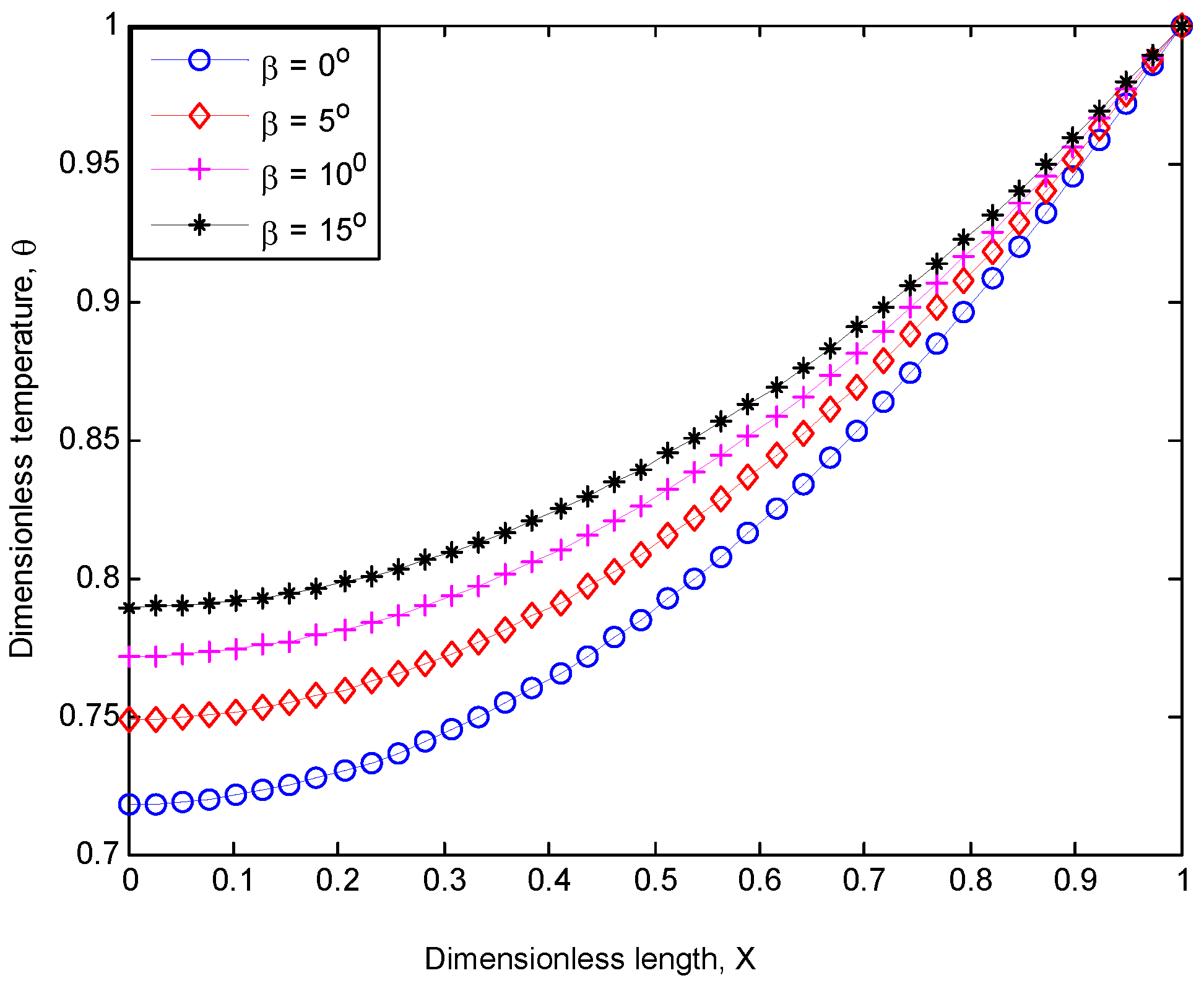
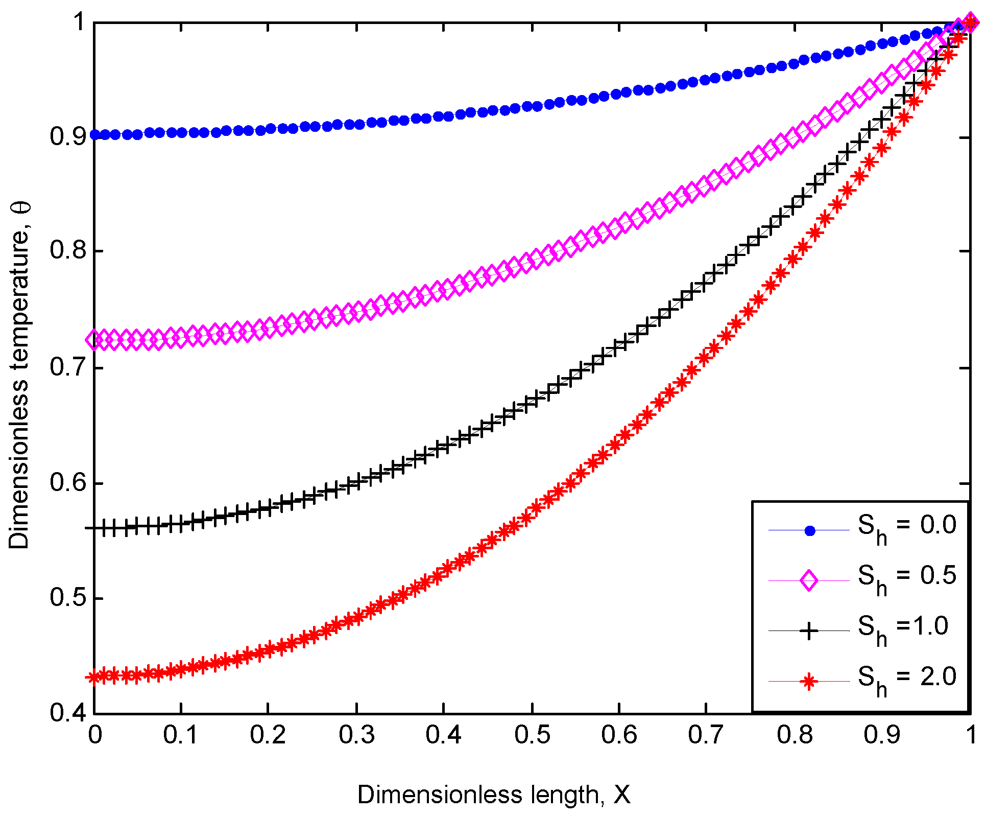
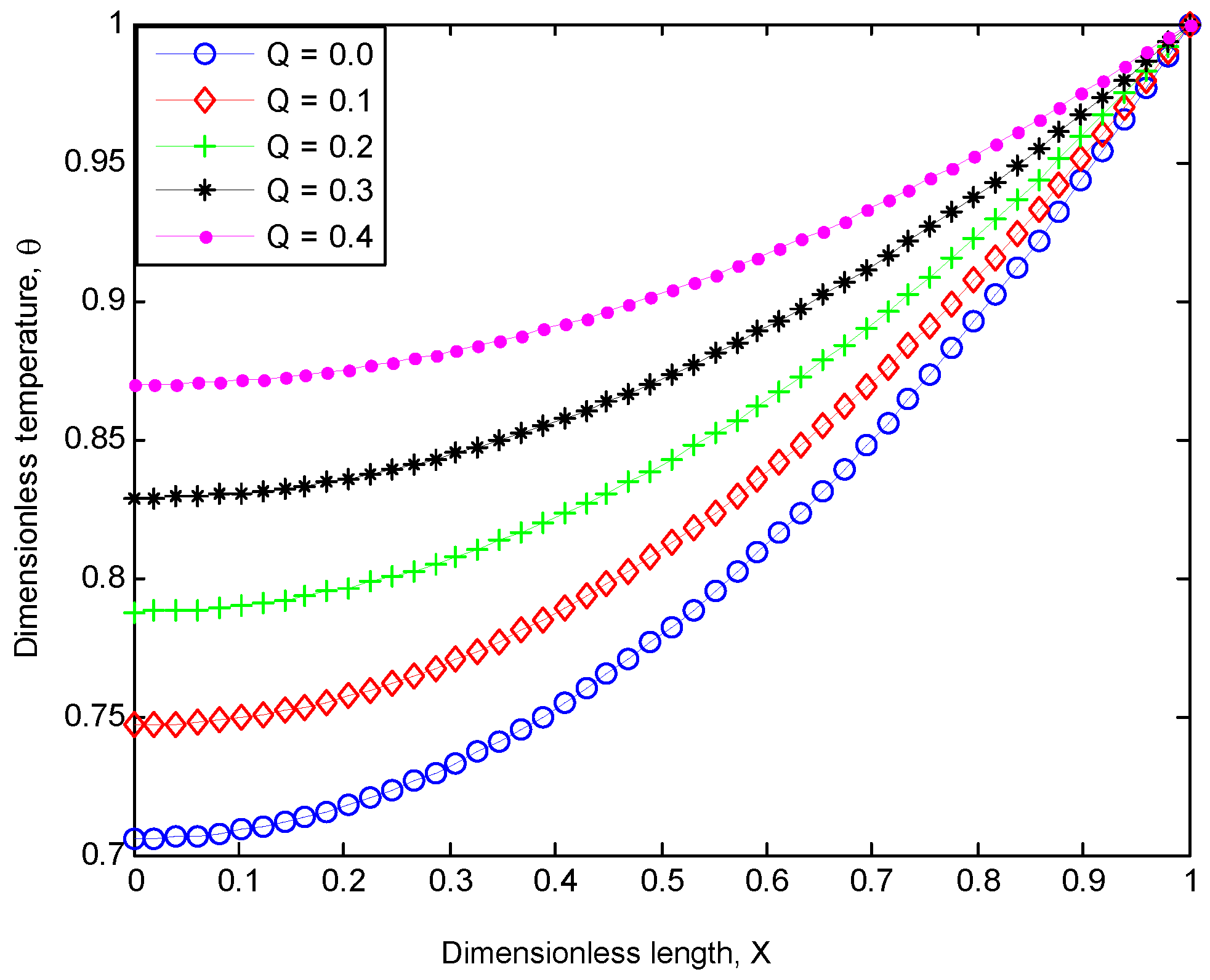
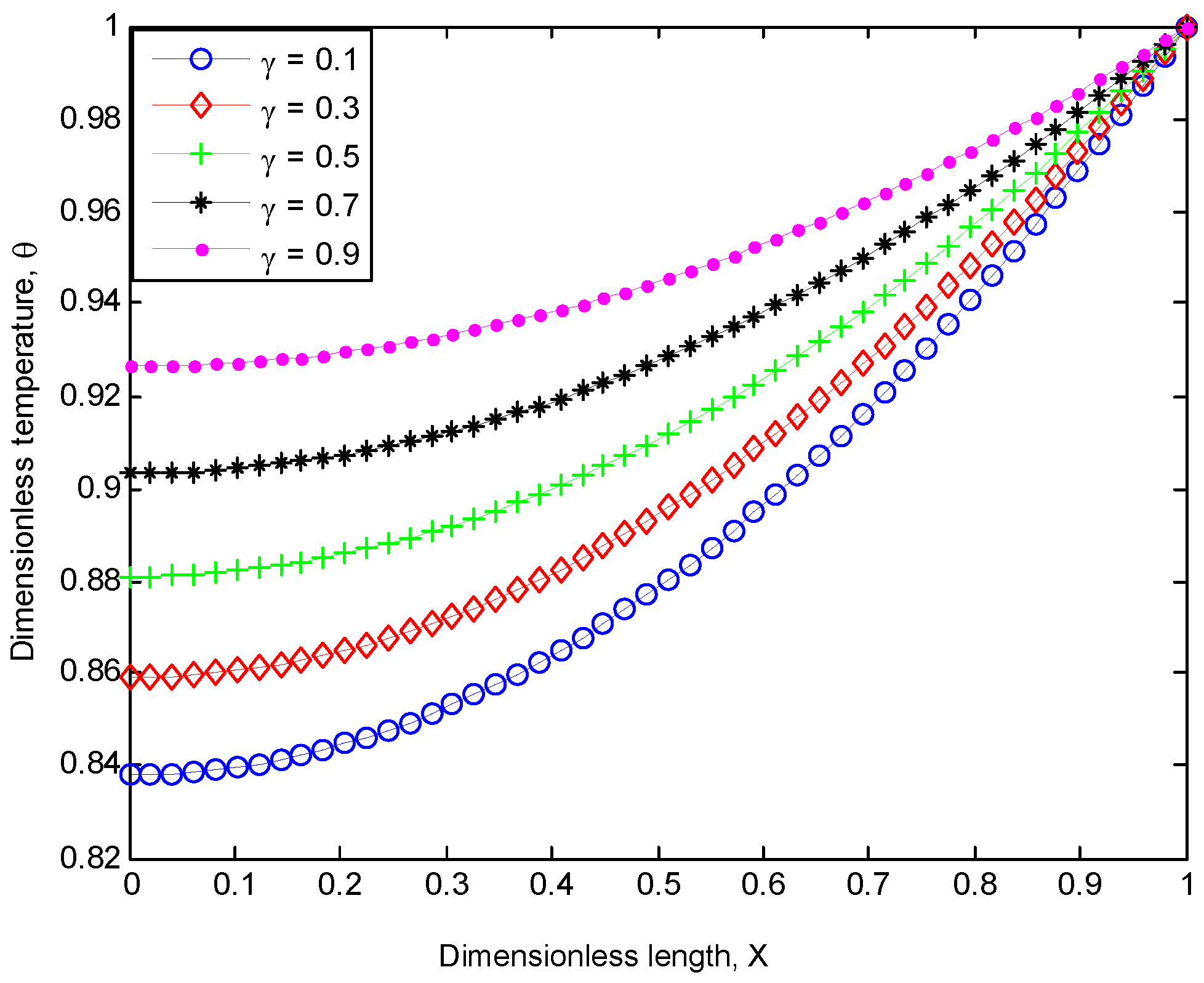
The developed analytical solutions presented in Section 3 are simulated in MATLAB and the results are presented in Figure 2, Figure 3, Figure 4, Figure 5, Figure 6 and Figure 7.
From Figure 2, the inclination effect on the performance of the porous fin is highlighted. It can be seen from Figure 2 that the inclined porous fin exhibits improved thermal performance than the corresponding vertical heat sink of equal dimension. In addition, the thermal performance of the inclined or tilted fin increases with decrease in the length–thickness aspect ratio of the fin. In addition, Figure 3 shows the effect of porosity on the temperature distribution of the fin. From Figure 3, it can be observed that the temperature of the porous fin decreases and drops rapidly as the porosity parameter increases. This overall implication of this effect is that increase in porosity improves the performance of the fin.
Figure 4 shows the effect of heat generated internally on the temperature distribution of porous fin, whilst Figure 5 presents the influence of the temperature-dependent internal heat generation on the temperature distribution of the fin. From both Figure 4 and Figure 5, it can be observed that as the temperature gradient of the fins decreases, the internal heat generation parameters increases, which consequently decreases the rate of heat transferred in the fin.
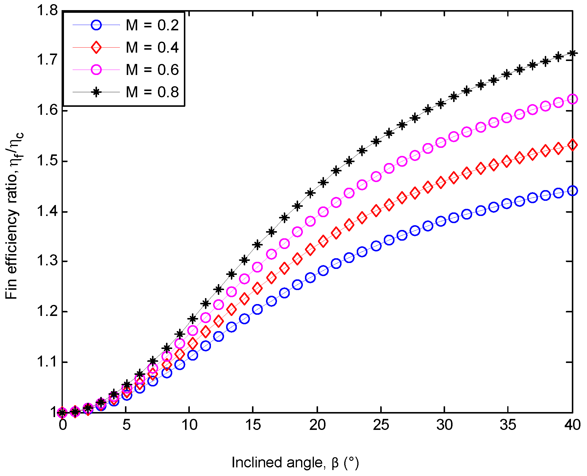
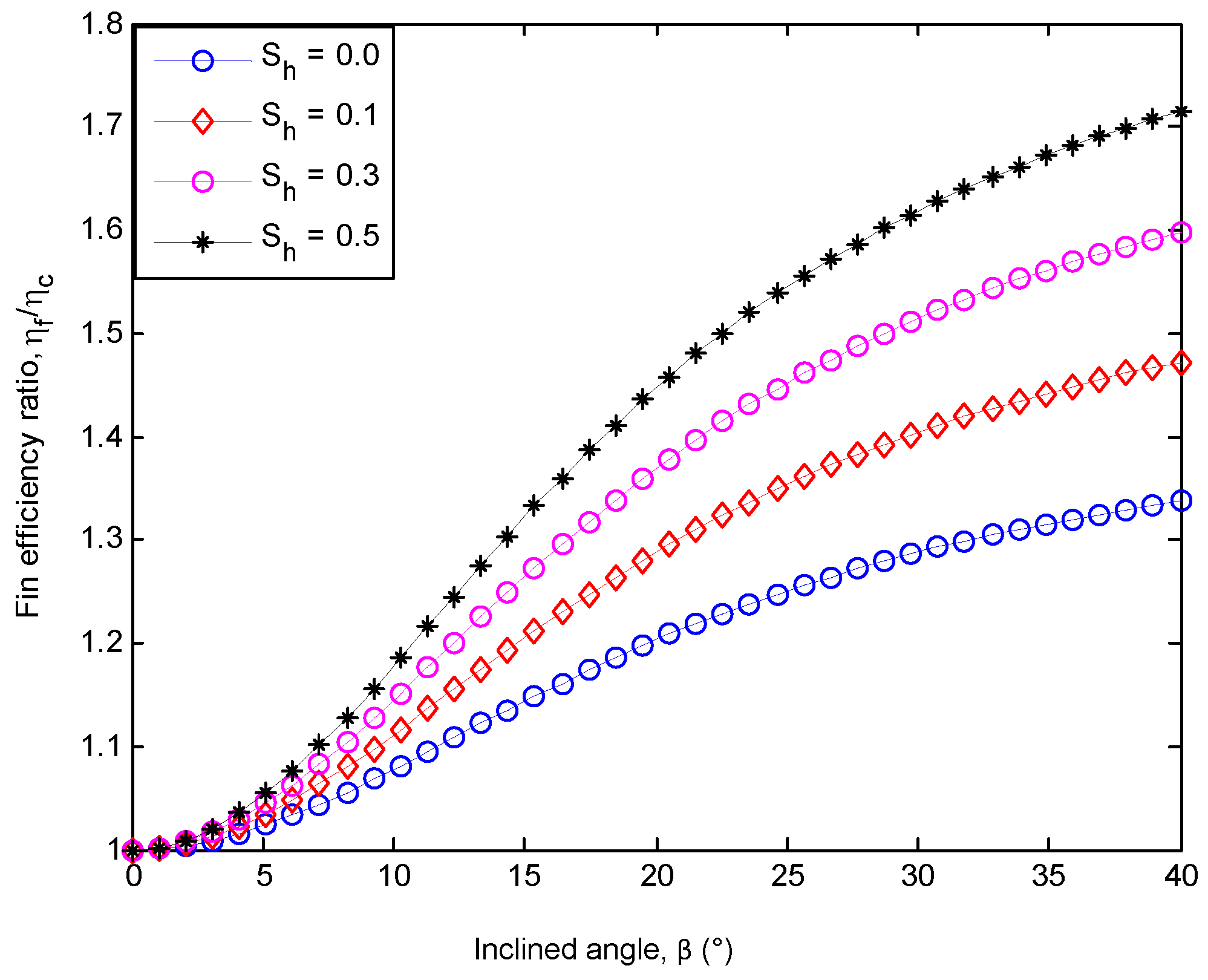
From Figure 6 and Figure 7, we highlight the effects of thermo-geometric and porosity variable on the efficiency ratio of the inclined fin to vertical fin. From the figures, it can be observed that the efficiency ratio of the inclined fin to the vertical fin is greater than one for all cases considered. Moreover, the increased temperature distribution by convection in the inclined porous fin is due to the effective shorter length of the fin caused by the tilted angle, β as depicted in Figure 1c.
From Table 1, we highlight a comparison of the present study using HPM with an established numerical result of Runge–Kutta. From Table 1, it could be seen that the result of HPM agrees excellently with the established result of Runge–Kutta which validates the accuracy of the present method for analysis of nonlinear heat transfer problem.

5. Conclusions

In this article, the effect of inclination on the thermal behavior of a porous fin heat sink has been investigated using HPM. From the analysis, it is established that the inclined porous fin in heat sink shows improved thermal performance than the corresponding vertical heat sink of the same size and geometry. In addition, the thermal performance of the inclined or tilted fin increases as the aspect ratio of the fin decreases. Furthermore, the study reveals that as the internal heat generation parameter increases the dimensionless temperature profile of the porous fin increases, which consequently, increases the rate of heat transfer in the fin. The obtained results using HPM in this work highlight the efficiency of the method for the analysis of nonlinear heat transfer problems.

Author Contributions

Conceptualization, G.O., G.S. and R.A.; Methodology, G.O. and G.S.; Formal Analysis, G.O and G.S.; Validation; Y.A.; Writing Original Draft Preparation, G.O., G.S., Review & Editing, G.O.; Supervision, R.A.

Acknowledgements

This work is supported in part by the Tertiary Education Trust Fund of Federal Government of Nigeria, and the European Union’s Horizon 2020 research and innovation programme under grant agreement H2020-MSCA-ITN-2016SECRET-722424.

Conflict of Interest

The authors declare no conflict of interest.

Abbreviations

Terminology
AFin cross-sectional area
AbBase area of the fin
AsFin surface area
heffHeat coefficient at fin base
cpSpecific heat of the fluid passing through the porous fin
KPermeability
MThermo-geometric parameter
m ˙ Saturated fluid mass flowage
NuNusselt number
PFin perimeter
tFin thickness
qRate of heat transfer
XDimensionless length
qInternal heat generation
GrGrashoff’s number
βInclination angle.
ShPorosity term.
MConvective heat parameter
TTemperature
TaAmbient temperature
TbTemperature at the base of the fin
VAverage velocity of the fluid passing through the porous fin
Greek Symbols
βInclination angle
θTemperature (Dimensionless)
ηFin efficiency
βthCoefficient of thermal expansion
υKinematic viscosity
ρFluid density
Subscripts
sSolid properties
fFluid properties
effEffective porous properties

References

  1. Kiwan, S.; Al-Nimr, M.A. Using Porous Fins for Heat Transfer Enhancement. J. Heat Transf. 2000, 123, 790–795. [Google Scholar] [CrossRef]
  2. Ghasemi, S.E.; Hatami, M.; Ganji, D.D. Thermal analysis of convective fin with temperature-dependent thermal conductivity and heat generation. Case Stud. Thermal Eng. 2014, 4, 1–8. [Google Scholar] [CrossRef]
  3. Das, R. Estimation of parameters in a fin with temperature-dependent thermal conductivity and radiation. Proc. Inst. Mech. Eng. Part E J. Process Mech. Eng. 2016, 230, 474–485. [Google Scholar] [CrossRef]
  4. Kiwan, S.; Zeitoun, O. Natural convection in a horizontal cylindrical annulus using porous fins. Int. J. Numer. Methods Heat Fluid Flow 2008, 18, 618–634. [Google Scholar] [CrossRef]
  5. Gorla, R.S.R.; Bakier, A.Y. Thermal analysis of natural convection and radiation in porous fins. Int. Commun. Heat Mass Transf. 2011, 38, 638–645. [Google Scholar] [CrossRef]
  6. Saedodin, S.; Sadeghi, S. Temperature Distribution in Long Porous Fins in Natural Convection Condition. Middle East J. Sci. Res. 2013, 13, 812. [Google Scholar]
  7. Alshuraiaan, B.; Khanafer, K. The effect of the position of the heated thin porous fin on the laminar natural convection heat transfer in a differentially heated cavity. Int. Commun. Heat Mass Transf. 2016, 78, 190–199. [Google Scholar] [CrossRef]
  8. Sobamowo, M.G.; Kamiyo, O.M.; Adeleye, O.A. Thermal performance analysis of a natural convection porous fin with temperature-dependent thermal conductivity and internal heat generation. Therm. Sci. Eng. Prog. 2017, 1, 39–52. [Google Scholar] [CrossRef]
  9. Shateri, A.R.; Salahshour, B. Comprehensive thermal performance of convection–radiation longitudinal porous fins with various profiles and multiple nonlinearities. Int. J. Mech. Sci. 2018, 136, 252–263. [Google Scholar] [CrossRef]
  10. Oguntala, G.A.; Abd-Alhameed, R.A. Haar Wavelet Collocation Method for Thermal Analysis of Porous Fin with Temperature-Dependent Thermal Conductivity and Internal Heat Generation. J. Appl. Comput. Mech. 2017, 3, 185–191. [Google Scholar]
  11. Oguntala, G.; Abd-Alhameed, R.A.; Sobamowo, G.; Danjuma, I. Performance, Thermal Stability and Optimum Design Analyses of Rectangular Fin with Temperature-Dependent Thermal Properties and Internal Heat Generation. J. Comput. Appl. Mech. 2018, 49, 37–43. [Google Scholar]
  12. Ma, J.; Sun, Y.; Li, B.; Chen, H. Spectral collocation method for radiative–conductive porous fin with temperature dependent properties. Energy Convers. Manag. 2016, 111, 279–288. [Google Scholar] [CrossRef]
  13. Oguntala, G.; Abd-Alhameed, R.A. Thermal Analysis of Convective-Radiative Fin with Temperature-Dependent Thermal Conductivity Using Chebychev Spectral Collocation Method. J. Appl. Comput. Mech. 2018, 4, 87–94. [Google Scholar]
  14. Oguntala, G.A.; Abd-Alhameed, R.A.; Sobamowo, G.M.; Eya, N. Effects of particles deposition on thermal performance of a convective-radiative heat sink porous fin of an electronic component. Therm. Sci. Eng. Prog. 2018, 6, 177–185. [Google Scholar] [CrossRef]
  15. Oguntala, G.; Abd-Alhameed, R.A.; Sobamowo, G.; Abdullahi, H.S. Improved thermal management of computer microprocessors using cylindrical-coordinate micro-fin heat sink with artificial surface roughness. Eng. Sci. Technol. Int. J. 2018, 21, 736–744. [Google Scholar] [CrossRef]
  16. Ma, J.; Sun, Y.; Li, B. Simulation of combined conductive, convective and radiative heat transfer in moving irregular porous fins by spectral element method. Int. J. Therm. Sci. 2017, 118, 475–487. [Google Scholar] [CrossRef]
  17. Jayesimi, L.; Oguntala, G. Prediction of Temperature distribution in Straight Fin with Variable Thermal Conductivity and Internal Heat Generation using Legendre Wavelet Collocation Method. J. Comput. Appl. Mech. 2017, 48, 217–224. [Google Scholar]
  18. Roy, P.K.; Mondal, H.; Mallick, A. A decomposition method for convective–radiative fin with heat generation. Ain Shams Eng. J. 2015, 6, 307–313. [Google Scholar] [CrossRef]
  19. Bhanja, D.; Kundu, B.; Mandal, P.K. Thermal Analysis of Porous Pin Fin Used for Electronic Cooling. Proc. Eng. 2013, 64, 956–965. [Google Scholar] [CrossRef]
  20. Torabi, M.; Yaghoobi, H. Series Solution for Convective-Radiative Porous Fin Using Differential Transformation Method. J. Porous Media 2013, 16, 341–349. [Google Scholar] [CrossRef]
  21. Moradi, A.; Hayat, T.; Alsaedi, A. Convection-radiation thermal analysis of triangular porous fins with temperature-dependent thermal conductivity by DTM. Energy Convers. Manag. 2014, 77, 70–77. [Google Scholar] [CrossRef]
  22. Oguntala, G.; Abd-Alhameed, R.A. Performance of convective-radiative porous fin heat sink under the influence of particle deposition and adhesion for thermal enhancement of electronic components. Karbala Int. J. Mod. Sci. 2018, 4, 297–312. [Google Scholar] [CrossRef]
  23. Coşkun, S.B.; Atay, M.T. Fin efficiency analysis of convective straight fins with temperature-dependent thermal conductivity using variational iteration method. Appl. Therm. Eng. 2008, 28, 2345–2352. [Google Scholar] [CrossRef]
  24. Hoshyar, H.; Ganji, D.D.; Abbasi, M. Determination of Temperature Distribution for Porous Fin with Temperature-Dependent Heat Generation by Homotopy Analysis Method. J. Appl. Mech. Eng. 2015, 4, 153. [Google Scholar]
  25. Mosayebidorcheh, S.; Sheikholeslami, M.; Hatami, M.; Ganji, D.D. Analysis of Turbulent MHD Couette Nanofluid Flow and Heat Transfer Using Hybrid DTM–FDM. Particuology 2016, 26, 95–101. [Google Scholar] [CrossRef]
  26. Amirkolaei, R.S.; Ganji, D.D.; Slarian, H. Determination of Temperature Distribution for Porous Fin Which is Exposed to Uniform Magnetic Field to a Vertical Isothermal Surface by Homotopy Analysis Method and Collocation Method. Indian J. Sci. Res. 2014, 1, 215–222. [Google Scholar]
  27. Hoshyar, H.; Rahimipetroudi, I.; Ganji, D.D.; Majidian, A.R. Thermal performance of porous fins with temperature-dependent heat generation via the homotopy perturbation method and Collocation method. J. Appl. Math. Comput. Mech. 2015, 14, 53–65. [Google Scholar] [CrossRef]
  28. Tari, I.; Mehrtash, M. Natural convection heat transfer from horizontal and slightly inclined plate-fin heat sinks. Appl. Therm. Eng. 2013, 61, 728–736. [Google Scholar] [CrossRef]
  29. Ayaskanta, A.; Huang, L.; Simon, T.; Yeom, T.; North, M.; Cui, T. Heat Transfer Enhancement of a Heat Sink by Inclined Synthetic Jets for Electronics Cooling. In Proceedings of the ASME 2013 7th International Conference on Energy Sustainability and the ASME 2013 11th International Conference on Fuel Cell Science, Engineering and Technology, Minneapolis, MN, USA, 14–19 July 2013. [Google Scholar]
  30. Oguntala, G.; Abd-Alhameed, R.A.; Sobamowo, G. On the effect of magnetic field on thermal performance of convective-radiative fin with temperature-dependent thermal conductivity. Karbala Int. J. Mod. Sci. 2018, 4, 1–11. [Google Scholar] [CrossRef]
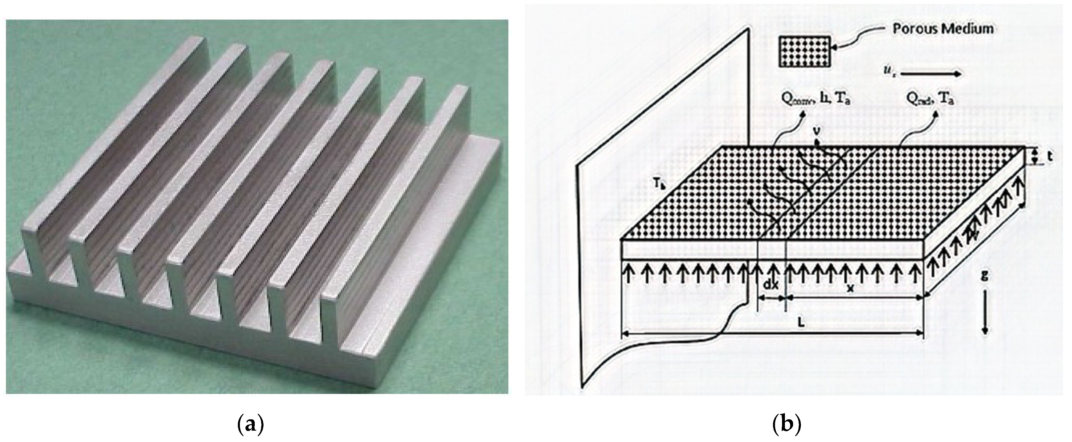
Figure 1. (a) Porous heat sink; (b) schematic of the heat process; (c) plain view of vertical fins heat sink; (d) plain view of inclined porous fins heat sink.
Mca 23 00062 g001aMca 23 00062 g001b
Figure 2. Inclination effect on the fin performance.
Mca 23 00062 g002
Figure 3. Porosity effect on the performance of the inclined fin.
Mca 23 00062 g003
Figure 4. Effect of heat generation on the performance of the inclined fin.
Mca 23 00062 g004
Figure 5. Effect of temperature-dependent heat generation on the performance of the inclined fin.
Mca 23 00062 g005
Figure 6. Thermo-geometric variable effect on efficiency ratio of inclined to vertical porous fins.
Mca 23 00062 g006
Figure 7. Porosity variable effect on efficiency ratio of inclined to vertical porous fins.
Mca 23 00062 g007
Table 1. Comparison of results.
xNumerical Method (Runge-Kutta)HPM (Present Study)Absolute Error
0.000.8634992310.8634996640.000000433
0.050.8638285680.8638290460.000000478
0.100.8648170900.8648175390.000000449
0.150.8664661820.8664657430.000000439
0.200.8687767090.8687762610.000000448
0.250.8717515550.8717511040.000000451
0.300.8753938590.8753934040.000000455
0.350.8797074720.8797070100.000000462
0.400.8846969670.8846965000.000000467
0.450.8903676500.8903671810.000000469
0.500.8967255690.8967250960.000000473
0.550.9037775310.9037770600.000000471
0.600.9115311200.9115306580.000000462
0.650.9199947100.9199942590.000000451
0.700.9291774880.9291770560.000000432
0.750.9390894760.9390890790.000000397
0.800.9497415550.9497412030.000000352
0.850.9611454910.9611451890.000000302
0.900.9733139640.9733137640.000000200
0.950.9862605990.9862605490.000000005
1.001.0000000001.0000000000.000000000