Article

Two-Dimensional Exact Subdomain Technique of Switched Reluctance Machines with Sinusoidal Current Excitation

1
Laboratoire de Recherche en Electrotechnique, Ecole Nationale Polytechnique, 16200 Algiers, Algeria
2
Département ENERGIE, FEMTO-ST, CNRS, Univ. Bourgogne Franche-Comté, F90000 Belfort, France
*
Author to whom correspondence should be addressed.
Math. Comput. Appl. 2018, 23(4), 59; https://doi.org/10.3390/mca23040059
Submission received: 18 September 2018 / Revised: 9 October 2018 / Accepted: 10 October 2018 / Published: 11 October 2018
(This article belongs to the Special Issue Mathematical Models for the Design of Electrical Machines)

Abstract

:
This paper presents a two-dimensional (2D) exact subdomain technique in polar coordinates considering the iron relative permeability in 6/4 switched reluctance machines (SRM) supplied by sinusoidal waveform of current (aka, variable flux reluctance machines). In non-periodic regions (e.g., rotor and/or stator slots/teeth), magnetostatic Maxwell’s equations are solved considering non-homogeneous Neumann boundary conditions (BCs). The general solutions of magnetic vector potential in all subdomains are obtained by applying the interface conditions (ICs) in both directions (i.e., r- and θ-edges ICs). The global saturation effect is taken into account, with a constant magnetic permeability corresponding to the linear zone of the nonlinear B(H) curve. In this investigation, the magnetic flux density distribution inside the electrical machine, the static/dynamic electromagnetic torques, the magnetic flux linkage, the self-/mutual inductances, the magnetic pressures, and the unbalanced magnetic forces (UMFs) have been calculated for 6/4 SRM with two various non-overlapping (or concentrated) windings. One of the case studies is a M1 with a non-overlapping all teeth wound winding (double-layer winding with left and right layer) and the other is a M2 with a non-overlapping alternate teeth wound winding (single-layer winding). It is important to note that the developed semi-analytical model based on the 2D exact subdomain technique is also valid for any number of slot/pole combinations and for non-overlapping teeth wound windings with a single/double layer. Finally, the semi-analytical results have been performed for different values of iron core relative permeability (viz., 100 and 800), and compared with those obtained by the 2D finite-element method (FEM). The comparisons with FEM show good results for the proposed approach.

1. Introduction

Benefiting from the advantages of a simple mechanical structure—the rotor does not carry any windings, commutators, or permanent magnets (PMs)—and a robust, fault-tolerant nature, low-cost maintenance, high-thermal capability, and high-speed potential [1,2,3], SRM is receiving renewed attention as a viable candidate for various adjustable-speed and high-torque applications such as in the automotive and traction fields [4,5,6,7,8].
However, a major disadvantage of this machine is the undesirable electromagnetic vibration and acoustic noise, which are mainly excited by the radial UMF acting on the salient stator and rotor poles [9,10]. Moreover, it poses a drawback for SRM in noise-sensitive applications and still creates bottlenecks in vehicle propulsion. It is important to consider noise and vibration problems during the process of electrical machine design. Electrical machine noise and vibration are mainly of electromagnetic, aerodynamic, and mechanical origin, the most important of which are generated by electromagnetic sources [11]. Also, in SRM, the attraction magnetic force can be divided into tangential and radial components relative to the rotor. The tangential magnetic force is converted into rotational torque, and the radial magnetic force converts into magnetic pressure equal to the radial magnetic force per unit area of the stator tooth and UMFs, which contributes to the radial vibration behaviour and therefore the motor noise [9,12]. A perfect machine with balanced stator windings should have net zero UMFs on the stator structure. However, UMFs can be present in machines having diametrically asymmetric disposition of slots and phase windings [13,14]. This magnetic force acts on the stator of these machine configurations due to an asymmetric magnetic field distribution in the air gap.
In the interest for design and optimization of electrical machines, there are various modelling methods; the first step in these is the magnetic field calculation. Some comprehensive reviews of the models of electrical machines for magnetic field prediction along with their (dis)advantages can be found in [15,16,17,18,19,20,21,22,23,24] and their references. Currently, the Maxwell‒Fourier method is one of the most used semi-analytical methods, and combines the very accurate electromagnetic performances calculation with a reduced computation time compared to numerical methods. In models from this method (viz., multi-layer models, eigenvalues model, and subdomain technique), the magnetic field solutions are based on the formal resolution of Maxwell’s equations by using the separation of variables method and the Fourier’s series. In electromagnetic devices, the major assumption is that an infinite permeability of iron parts has to be assumed [25]. Therefore, the global and/or local saturation effect is neglected. It is interesting to note that an overview of the existing (semi-)analytical models in the Maxwell‒Fourier method with a global and/or local saturation effect has been realized in [24], where some details and the (dis)advantages of these techniques can be found. To overcome that issue, Spranger et al. (2016) [21] and Dubas et al. (2017) [24,26] have recently developed new techniques to account for finite soft-magnetic material permeabilities:
  • multi-layer models using the convolution theorem (i.e., Cauchy’s product theorem). The adjacent regions (e.g., rotor and/or stator slots/teeth) are assumed to be one homogeneous region with a relative permeability developed as a Fourier’s series expansion;
  • the subdomain technique using a superposition that allows for any non-periodic subdomain. The subdomain connection is performed directly in both directions. The general solutions of Maxwell’s equations are deduced by applying the principle of superposition by respecting the BCs on the various edges of subdomains.
For the same reason, another technique based on subdomain technique and Taylor polynomial has been developed and only applied in spoke-type PM synchronous machines (PMSM) [27,28]. Spranger’s approach has been extended and used in different machines with only the global saturation effect. It has been applied with the finite soft-magnetic material permeability in synchronous reluctance machine [29], surface-mounted PMSM [30], and many structures of PMSMs (i.e., for inset-/surface-/spoke-type PMSMs with different PM magnetization patterns and internal/external rotor) [31], with the nonlinear B(H) curve in switched reluctance machine [32,33]. The Dubas superposition technique has been implemented in radial-flux electrical machines with(out) PMs supplied by a direct or alternate current (with any waveforms) [34]. This technique has been extended to: (i) the thermal modelling for the steady-state temperature distribution in rotating electrical machines [35], and (ii) elementary subdomains in the rotor and stator regions for full prediction of magnetic field in rotating electrical machines with the local saturation effect solving by the Newton‒Raphson iterative algorithm [36]. The Dubas superposition technique is very interesting since, like Spranger’s approach, it enables the magnetic field calculation in iron parts of slotted structures. Apart from its complexity, the main downfall of Spranger’s approach is that it suffers from the Gibb’s phenomenon at boundaries between slots and teeth. This introduces inaccuracies in the computation of the field and results in higher computational times [37].
In this paper, the authors propose applying the Dubas superposition technique in polar coordinates [26] to SRM with sinusoidal current excitation, which has not yet been realized in the literature. The soft magnetic material permeability is constant corresponding to the linear zone of the B(H) curve. Nevertheless, as in [33,36], it should be mentioned that the material properties could be updated iteratively to take the nonlinear B(H) curve of the material into account. However, this is beyond the scope of the paper. In this investigation, the magnetic flux density distribution inside the machine, electromagnetic performances and non-intrinsic UMFs have been calculated for 6/4 SRM supplied by sinusoidal waveform of current with two various non-overlapping (or concentrated) windings. One of the case studies is a M1 with a non-overlapping all teeth wound winding (double-layer winding with left and right layer) and the other is a M2 with a non-overlapping alternate teeth wound winding (single-layer winding). All results obtained with the proposed semi-analytical model are verified by 2D FEM [38] for different values of iron core relative permeability (viz., 100 and 800). The comparisons with FEM show good results.

2. Studied SRMs and Magnetic Field Solutions

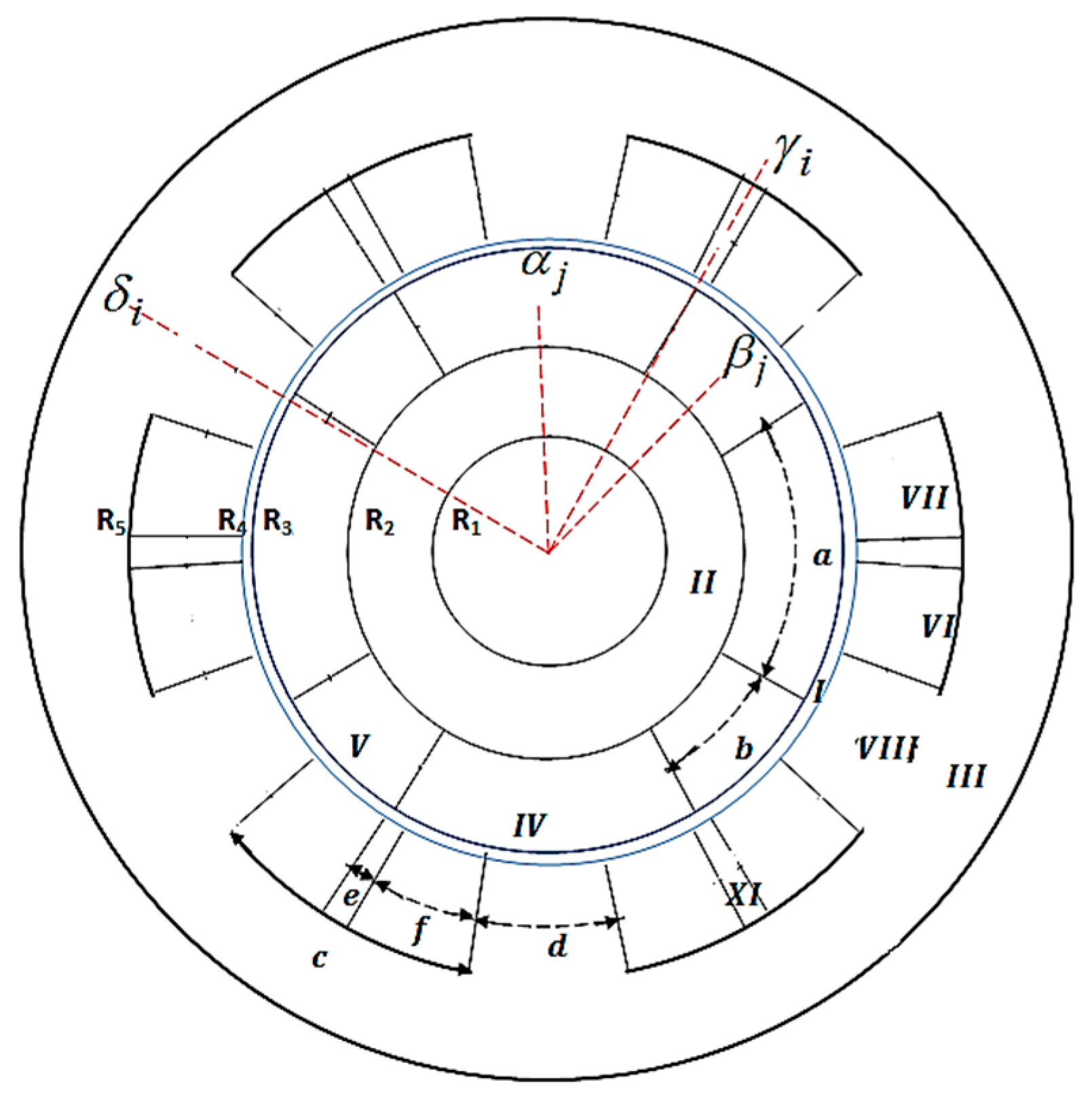
2.1. Machine Geometry and Assumptions

Figure 1 represents the studied SRMs having two various non-overlapping windings: (i) M1 with a non-overlapping all teeth wound winding (double-layer winding with left and right layer) (see Figure 1a), and (ii) M2 with a non-overlapping alternate teeth wound winding (single-layer winding) (see Figure 1b). The three-phase SRMs have six stator slots and four rotor slots, and do not contain any stator tooth tips. The main geometrical parameters of two studied SMRs are shown in Figure 1 and are given in Table 1 for the semi-analytical and numerical comparisons. These machines have been partitioned into nine regions as shown on Figure 2, viz.,
  • Region I is the air gap;
  • Regions II and III are the rotor yoke (i.e., between rotor shaft and rotor slots/teeth) and the stator yoke, respectively;
  • Region IV is the rotor slots;
  • Region V is the rotor teeth;
  • Regions VI and VII are the stator slots of the first layer (i.e., right in the slot) and second layer (i.e., left in the slot), respectively;
  • Region VIII is the stator teeth;
  • Region XI is the non-periodic air gap (i.e., between the two-layer winding of the stator slots).
The semi-analytical model, based on the exact subdomain technique, is formulated in 2D, in polar coordinates, and in magnetic vector potential with the following assumptions:
  • The end-effects are neglected, i.e., A = { 0 ;   0 ;   A z } ;
  • The eddy-current effects in the materials are neglected;
  • The current density in the stator slots has only one component along the z-axis, i.e., J = { 0 ;   0 ;   J z } ;
  • The magnetic materials are considered as isotropic with constant magnetic permeability corresponding to linear zone of the B(H) curve;
  • The stator and rotor slots/teeth have radial sides (see Figure 2).
However, it accounts for:
  • The internal/external rotor topology;
  • The saturation, slotting and curvature effect;
  • The (non-)overlapping winding distribution;
  • Any current waveform (i.e., sinusoidal or rectangular).

2.2. General Solution with Non-Homogeneous Neumann BCs

Magnetic vector potential A is calculated analytically with solving the magnetostatic Maxwell’s equations with the separation of variables method, viz.,
Δ   A = 0   in   Region   I ,   II ,   III ,   IV ,   V ,   VIII   and   XI ,
Δ   A = μ 0 J   in   Region   VI   and   VII ,
where μ 0 is the vacuum permeability.
According to [24,26], the solutions to A in all regions of conventional SRM are:
  • Air gap subdomain (Region I): The solution of (1) in Region I, r [ R 3 ;   R 4 ] & θ , is defined by:
    A z I = A 10 + A 20 ln ( r ) + n = 1 [ A 1 n ( r R 3 ) n + A 2 n ( r R 2 ) n ] sin ( n θ ) + n = 1 [ A 3 n ( r R 3 ) n + A 4 n ( r R 2 ) n ] cos ( n θ )
    where n is a positive integer, and { A 10 ;   A 20 ;   A 1 n ; A 4 n } are the integration constants of Region I.
  • Stator and rotor yoke subdomain (Region II and III): In adding Dirichlet BC of A at r = R 1 and r = R e x t , viz., A z I I ( R 1 , θ ) = 0 & A z I I I ( R e x t , θ ) = 0 , the solution of (1) in Region II, r [ R 1 ;   R 2 ] & θ , can be written as:
    A z I I = A 50 ln ( r R 1 ) + n = 1 A 5 n [ ( r R 1 ) n ( r R 1 ) n ] sin ( n θ ) + n = 1 A 6 n [ ( r R 1 ) n ( r R 1 ) n ] cos ( n θ )
    where { A 50 ;   A 5 n ;   A 6 n } are the integration constants of Region II.
The solution of Region III, r [ R 5 ;   R e x t ] & θ , is similar to (4) by replacing { A 50 ;   A 5 n ;   A 6 n } with { A 70 ;   A 7 n ;   A 8 n } and R 1 with R e x t .
  • i-th Stator slot subdomain (Region VI and VII): The solution of (2) in Region VI, r [ R 4 ; R 5 ] & θ [ γ 1 i f / 2 ; γ 1 i + f / 2 ] , is defined by:
    A z V I i ( r , θ ) = C 1 i 0 + C 2 i 0 ln ( r ) 1 4 μ 0 J 1 ( i ) z r 2 + m = 1 [ C 1 i m ( r R 5 ) ν m f + C 2 i m ( r R 4 ) ν m f ] cos [ ν m f ( θ γ 1 i + f 2 ) ] + k = 1 { C 3 i k sh [ λ k s ( θ γ 1 i + f 2 ) ] sh ( λ k s f ) + C 4 i k sh [ λ k s ( θ γ 1 i f 2 ) ] sh ( λ k s f ) } sin [ λ k s   ln ( r R 4 ) ]
    where m and k are positive integers, γ 1 i = γ i ( e + f ) / 2 and f are respectively the position and opening width of first layer winding in the i-th stator slot, { C 1 i 0 ;   C 2 i 0 ;   C 1 i m ;   C 2 i m ;   C 3 i k ;   C 4 i k } are the integration constants of Region VI, v m f = m π / f and λ k s = k π / ln ( R 5 / R 4 ) are respectively the periodicity of A z V I i in θ-and r-edges.
The solution of Region VII, r [ R 4 ; R 5 ] & θ [ γ 2 i f / 2 ;   γ 2 i + f / 2 ] , is similar to (5) by replacing { C 1 i 0 ;   C 2 i 0 ;   C 1 i m ;   C 2 i m ;   C 3 i k ;   C 4 i k } with { C 5 i 0 ;   C 6 i 0 ;   C 5 i m ;   C 6 i m ;   C 7 i k ;   C 8 i k } , J 1 ( i ) z with J 2 ( i ) z , and γ 1 i with γ 2 i = γ i + ( e + f ) / 2 .
  • i-th Non-periodic air gap and i-th stator tooth subdomain (Region XI and VIII): The solution of (1) in Region VIII, r [ R 4 ; R 5 ] & θ [ γ i e / 2 ; γ i + e / 2 ] , and in Region XI, r [ R 4 ; R 5 ] & θ [ δ i d / 2 ; δ i + d / 2 ] , can be obtained directly from (5) with J 1 ( i ) z = 0 .
For Region VIII, { C 1 i 0 ;   C 2 i 0 ;   C 1 i m ;   C 2 i m ;   C 3 i k ;   C 4 i k } is replaced by { D 1 i 0 ;   D 2 i 0 ;   D 1 i m ;   D 2 i m ;   D 3 i k ;   D 4 i k } , γ 1 i by γ i , f by e , and v m f by v m e = m π / e .
For Region IX, { C 1 i 0 ;   C 2 i 0 ;   C 1 i m ;   C 2 i m ;   C 3 i k ;   C 4 i k } is replaced by { D 1 i 0 ;   D 2 i 0 ;   D 1 i m ;   D 2 i m ;   D 3 i k ;   D 4 i k } , γ 1 i by δ i , f by d , and v m f by v m d = m π / d .
  • j-th Rotor slot and j-th rotor tooth subdomain (Region IV and V): The solution of (1) in Region IV, r [ R 2 ; R 3 ] & θ [ α j a / 2 ;   α j + a / 2 ] , is defined by:
    A z I V j ( r , θ ) = B 1 j 0 + B 2 j 0 ln ( r ) + m = 1 [ B 1 j m ( r R 3 ) ν m a + B 2 j m ( r R 2 ) ν m a ] cos [ ν m a ( θ α j + a 2 ) ] + k = 1 { B 3 j k sh [ λ k r ( θ α j + a 2 ) ] sh ( λ k r a ) + B 4 j k sh [ λ k r ( θ α j a 2 ) ] sh ( λ k r a ) } sin [ λ k r   ln ( r R 2 ) ]
    where α j and a are respectively the position and opening width of j-th rotor slot, { B 1 j 0 ;   B 2 j 0 ;   B 1 j m ;   B 2 j m ;   B 3 j k ;   B 4 j k } are the integration constants of Region IV, v m a = m π / a and λ k r = k π / ln ( R 3 / R 2 ) are respectively the periodicity of A z I V j in θ-and r-edges.
The solution of Region V, r [ R 2 ; R 3 ] & θ [ β j b / 2 ;   β j + b / 2 ] , is similar to (6) by replacing { B 1 j 0 ;   B 2 j 0 ;   B 1 j m ;   B 2 j m ;   B 3 j k ;   B 4 j k } with { B 5 j 0 ;   B 6 j 0 ;   B 5 j m ;   B 6 j m ;   B 7 j k ;   B 8 j k } , a with b , and α j with β j .

2.3. Magnetic Flux Density

The field vectors B = { B r ;   B θ ;   0 } and H = { H r ;   H θ ;   0 } are coupled by:
B = μ 0 H   in   Region   I ,   IV ,   VI ,   VII   and   XI ,
B = μ 0 μ r c H   in   Region   II ,   III ,   V   and   VIII ,
where μ r c is the relative recoil permeability of iron parts.
Using B = × A , the components of B = × A can be deduced by
B r = 1 r A z θ   and   B θ = A z r .

2.4. Stator Current Density Source

The stator current densities in the stator slots for double-layer concentrated winding are defined as [33]:
J 1 ( i ) = N c S C ( 1 ) T i g   and   J 2 ( i ) = N c S C ( 2 ) T i g .
where i g = [ i a i b i c ] is the vector of phase currents whose currents’ waveform is sinusoidal with a phase shift of 2 π / 3 electric, S = f ( R 5 2 R 4 2 ) / 2 is the surface of the stator slot coil, and C ( 1 ) T & C ( 2 ) T are the transpose of the connection matrix between the three phases and the stator slots that represent the distribution of stator windings in the slots of the M1 with all teeth wound (double-layer winding with left and right layer) (see Figure 1a) is given by [33]:
C ( 1 ) = [ 1 0 0 1 0 0 0 1 0 0 1 0 0 0 1 0 0 1 ]   and   C ( 2 ) = [ 0 0 1 0 0 1 1 0 0 1 0 0 0 1 0 0 1 0 ] .
For the M2 with alternate teeth wound (single-layer winding) (see Figure 1b), the same model is used with few modifications:
  • The opening of the non-periodic air gap will be equal to zero (i.e., e = 0);
  • The stator current density will be equal to J 1 ( i ) = J 2 ( i ) = N c S C ( 1 ) T i g with S = c ( R 5 2 R 4 2 ) / 2 and
    C ( 1 ) = [ 1 1 0 0 0 0 0 0 0 0 1 1 0 0 1 1 0 0 ] .
These connection matrices can be generated automatically by using the ANFRACTUS TOOL developed in [39].

2.5. Boundary Conditions

The ICs in this semi-analytical model can be divided into two types, viz.,
  • θ-edges ICs: over angle interval for given radius value { R 2 ;   R 3 ;   R 4 ; R 5 } ;
  • r-edges ICs: over radius interval for given angle { α j ± a / 2 ;   β j ± b / 2 ;   γ i ± c / 2 ;   δ i ± d / 2 ;   γ i ± e / 2 } .
Therefore, we obtain on the:
  • θ-edges ICs:
-
The ICs between Region II, IV and V at r = R 2 as:
A z I I ( R 2 , θ ) = A z I V j ( R 2 , θ )   for   θ [ α j a / 2 , α j + a / 2 ] ,
H θ I I ( R 2 , θ ) = H θ I V j ( R 2 , θ )   for   θ [ α j a / 2 , α j + a / 2 ] ,
H θ I I ( R 2 , θ ) = H θ V j ( R 2 , θ )   for   θ [ β j b / 2 , β j + b / 2 ] ,
-
The ICs between Region I, IV and V at r = R 3 are similar to (13)–(16) by replacing II with I and R 2 with R 3 .
-
The ICs between Region I, VI, VII, VIII and XI at r = R 4 as:
A z I ( R 4 , θ ) = A z V I I i ( R 4 , θ )   for   θ [ γ i + c / 2 f , γ i + c / 2 ] ,
A z I ( R 4 , θ ) = A z V I I I i ( R 4 , θ )   for   θ [ δ i d / 2 , δ i + d / 2 ] ,
A z I ( R 4 , θ ) = A z X I i ( R 4 , θ )   for   θ [ γ i e / 2 ,   γ i + e / 2 ] ,
H θ I ( R 4 , θ ) = A θ V I i ( R 4 , θ )   for   θ [ γ i c / 2 , γ i c / 2 + f ] ,
H θ I ( R 4 , θ ) = A θ V I I i ( R 4 , θ )   for   θ [ γ i + c / 2 f , γ i + c / 2 ] ,
H θ I ( R 4 , θ ) = A θ V I I i ( R 4 , θ )   for   θ [ δ i d / 2 , δ i + d / 2 ] ,
H θ I ( R 4 , θ ) = A θ X I i ( R 4 , θ )   for   θ [ γ i e / 2 , γ i + e / 2 ] ,
-
The ICs between Region III, VI, VII, VIII and XI at r = R 5 are similar to (17)–(24) by replacing I with III and R 4 with R 5 .
  • r-edges ICs:
-
The ICs between Region IV and V at α j + a / 2 = β j b / 2 and α j + 1 a / 2 = β j + b / 2 for r [ R 2 ;   R 3 ] :
A z I V j ( r , α j + a / 2 ) = A z V j ( r ,   β j b / 2 )     ,
H r I V j ( r , α j + a / 2 ) = H r V j ( r ,   β j b / 2 )   ,
A z I V ( j + 1 ) ( r , α j + 1 a / 2 ) = A z V j ( r ,   β j + b / 2 )     ,
H r I V ( j + 1 ) ( r , α j + 1 a / 2 ) = H r V j ( r ,   β j + b / 2 ) ,
-
The ICs between Region VII and VIII at γ i + c / 2 = δ i d / 2 and between Region VI and VIII at γ i + 1 c / 2 = δ i + d / 2 for r [ R 4 ;   R 5 ] :
A z V I I i ( r , γ i + c / 2 ) = A z V I I I i ( r ,   δ i d / 2 )   ,
H r V I I i ( r , γ i + c / 2 ) = H r   V I I I i ( r ,   δ i d / 2 ) ,
A z V I ( i + 1 ) ( r , γ i + 1 c / 2 ) = A z V I I I i ( r ,   δ i + d / 2 )   ,
H r V I ( i + 1 ) ( r , γ i + 1 c / 2 ) = H r V I I I i ( r ,   δ i + d / 2 )   ,
-
The ICs between Region VI and XI at γ i e / 2 = γ i c / 2 + f and between Region VII and XI at γ i + e / 2 = γ i + c / 2 f for r [ R 4 ;   R 5 ] :
A z V I i ( r , γ i c / 2 + f ) = A z X I i ( r ,   γ i e / 2 )   ,
H r V I i ( r , γ i c / 2 + f ) = H r   X I i ( r ,   γ i e / 2 ) ,
A z V I I i ( r , γ i + c / 2 f ) = A z X I i ( r ,   γ i + e / 2 )   ,
H r V I I i ( r , γ i + c / 2 f ) = H r X I i ( r ,   γ i + e / 2 )   ,
The system of the 36 BCs matrix (Equations (13)–(36)) is used to determine the coefficients of A in nine regions.
Figure 3 briefly represents a flowchart of the subdomain technique.
To solve the Cramer’s system, the number of integration constants is equal to 2 ( 4 N + 2 ) + 2 Q r ( 2 + 2 M + 2 K ) + 4 Q s ( 2 + 2 M + 2 K ) where N , M and K are the finite numbers of spatial harmonic terms in the various regions.

3. Electromagnetic Performance Calculations

3.1. Torque, Flux Linkage and Inductance Calculations

The semi-analytical model, based on the 2D exact subdomain technique and taking into account the iron core relative permeability, is used to determine the static/dynamic electromagnetic torque, the magnetic flux linkage, and the self-/mutual inductances whose various formulas have been clarified in [32,33].

3.2. Magnetic Pressure and UMF Calculations

The magnetic pressure P is the magnetic force per unit area of the stator tooth. It can be calculated both by Maxwell’s stress tensor and by finite element analysis. The r-and θ-components of P are calculated from the spatial magnetic field in the air gap middle at R g = ( R 4 + R 3 ) / 2 [14]:
P r ( θ r , θ ) = 1 2 μ 0 [ B r I ( R g , θ ) 2 B θ I ( R g , θ ) 2 ] ,
P θ ( θ r , θ ) = 1 μ 0 B r I ( R g , θ ) B θ I ( R g , θ ) ,
where θ r = Ω t + θ r s 0 is the temporal rotor angle with Ω the mechanical pulse and θ r s 0 the initial mechanical angular position between the rotor and the stator at the instant t = 0   s .
The x- and y-components of non-intrinsic UMF F are calculated at R g over θ = [ 0 ;   2 π ] as [14]:
F x ( θ r ) = R g L u 0 2 π [ P r ( θ ) cos ( θ ) P θ ( θ ) sin ( θ ) ] d θ ,
F y ( θ r ) = R g L u 0 2 π [ P r ( θ ) sin ( θ ) + P θ ( θ ) cos ( θ ) ] d θ ,
where L u is the axial length of the machine.
The acoustic noise and vibration is primarily due to the rotor eccentric position with respect to the stator bore, the UMF, if present in a motor even with perfectly aligned shaft, can create the rotor eccentricity. Moreover, P and F are transmitted through the teeth from the air gap to the yoke, which may cause deformation on the stator rings resulting from the rotor displacement and result in excessive acoustic noise and vibration. Different vibration modes are commonly called “mode shapes” having their own natural mode frequency. Any particular mode shape is excited when its natural mode frequency matches with any of the harmonics of P and F [40].

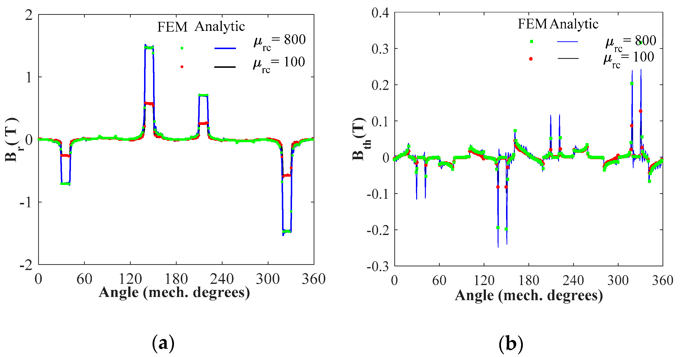
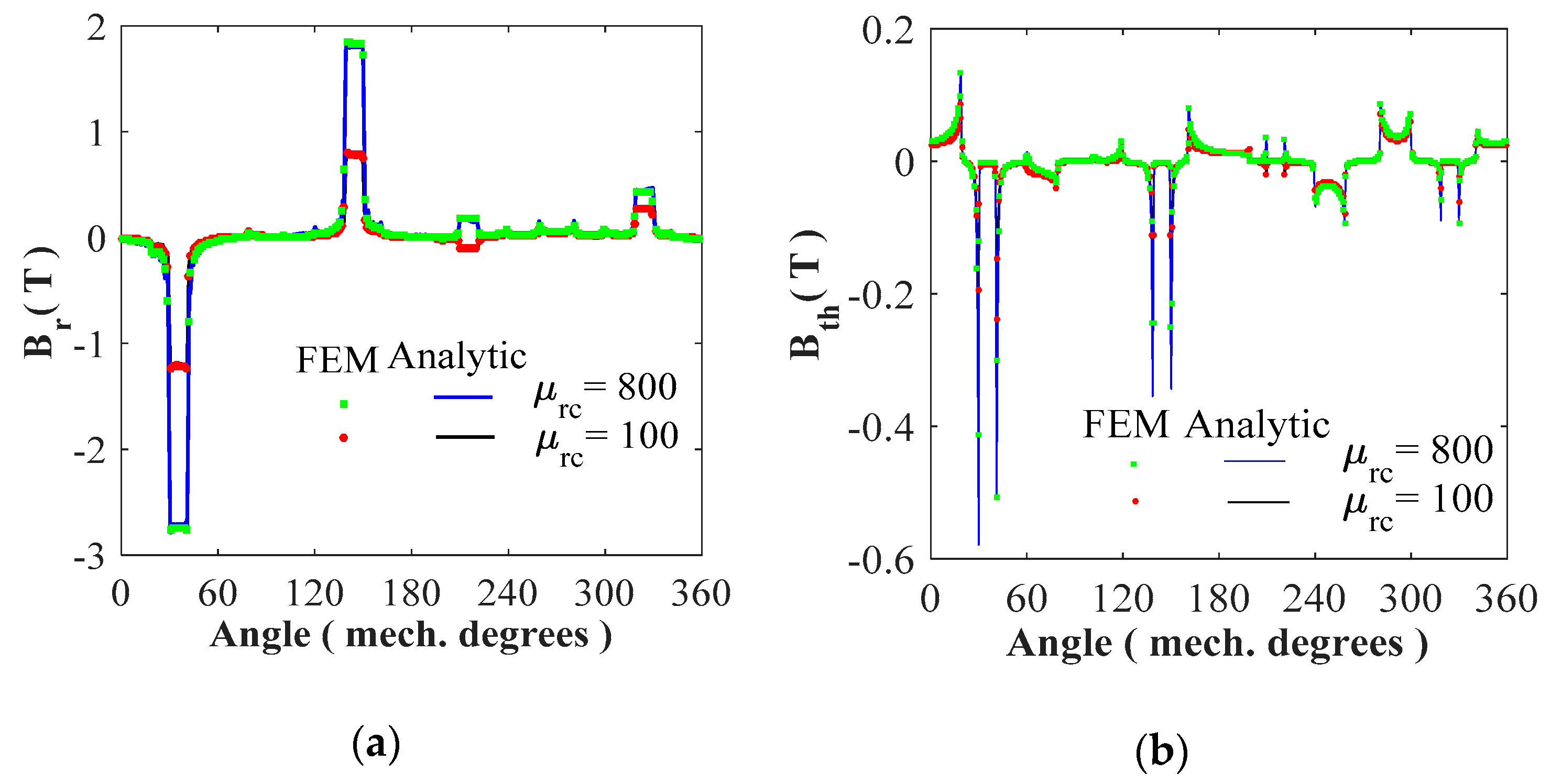
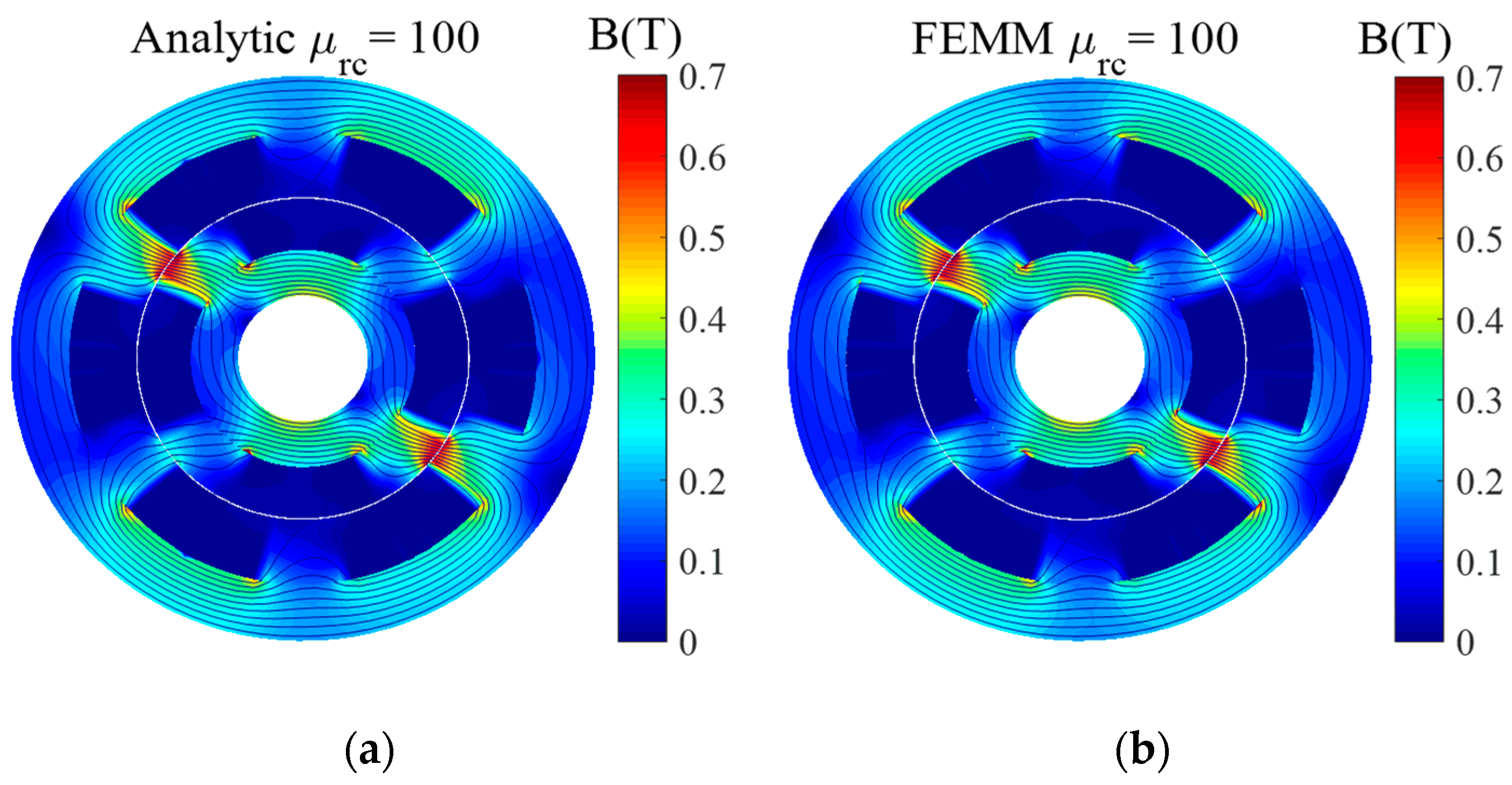
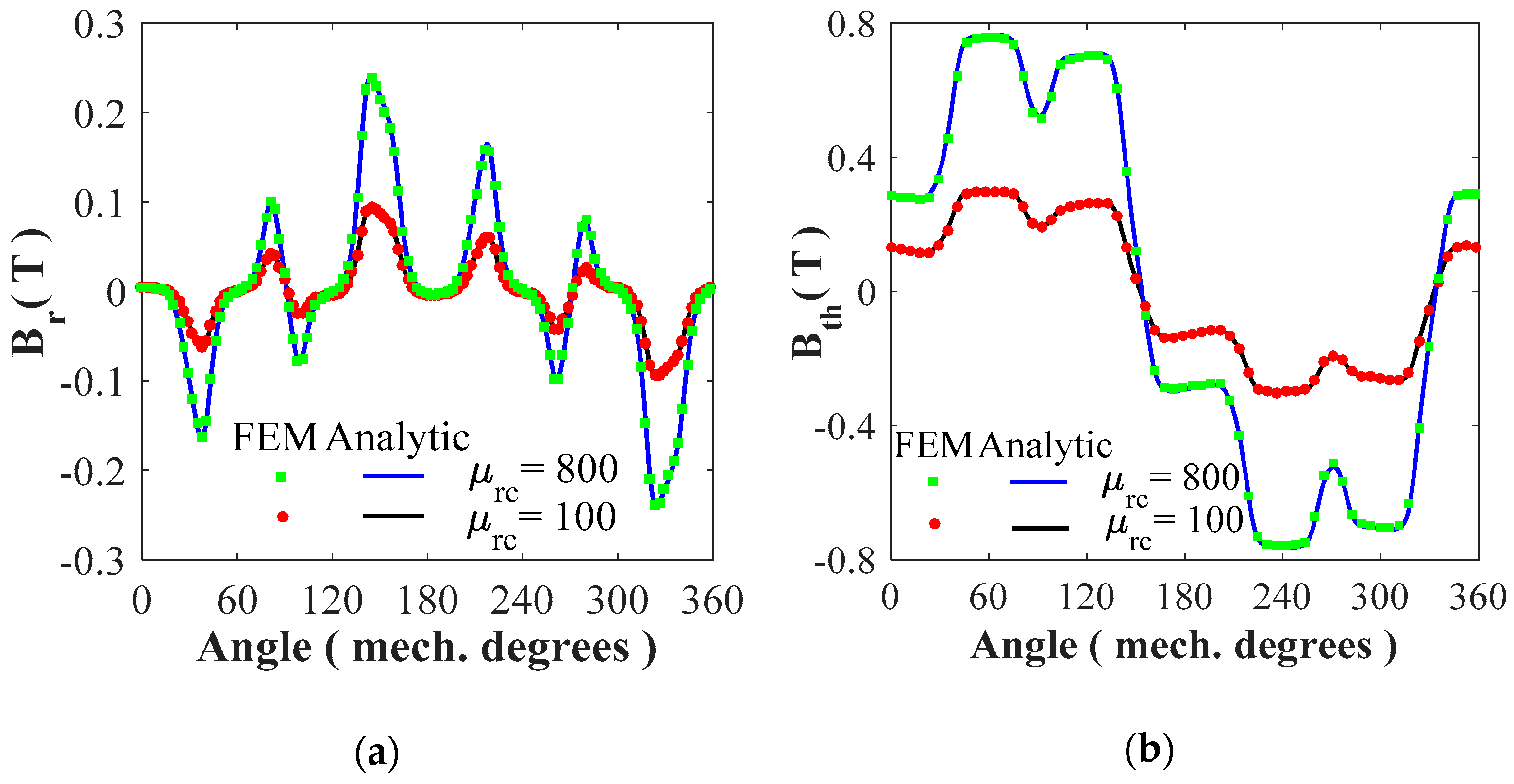
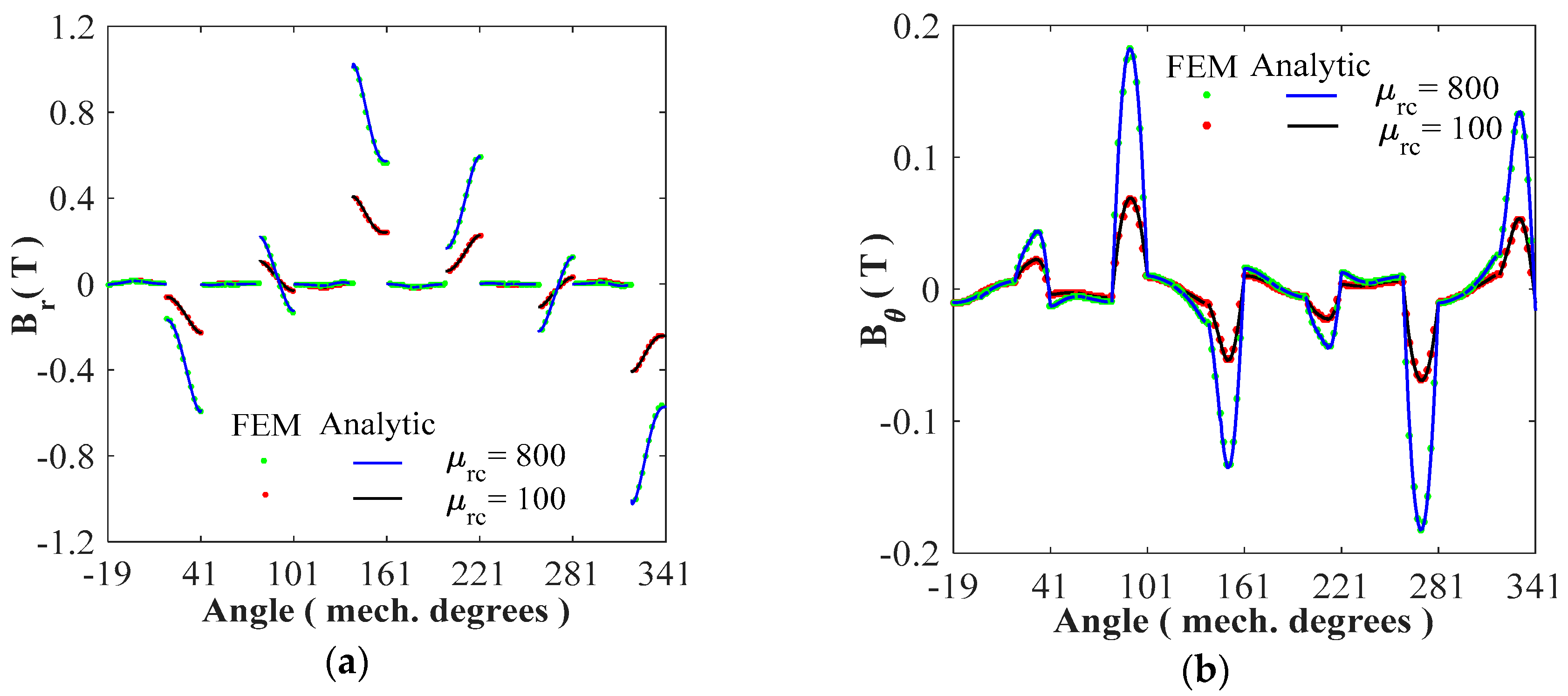
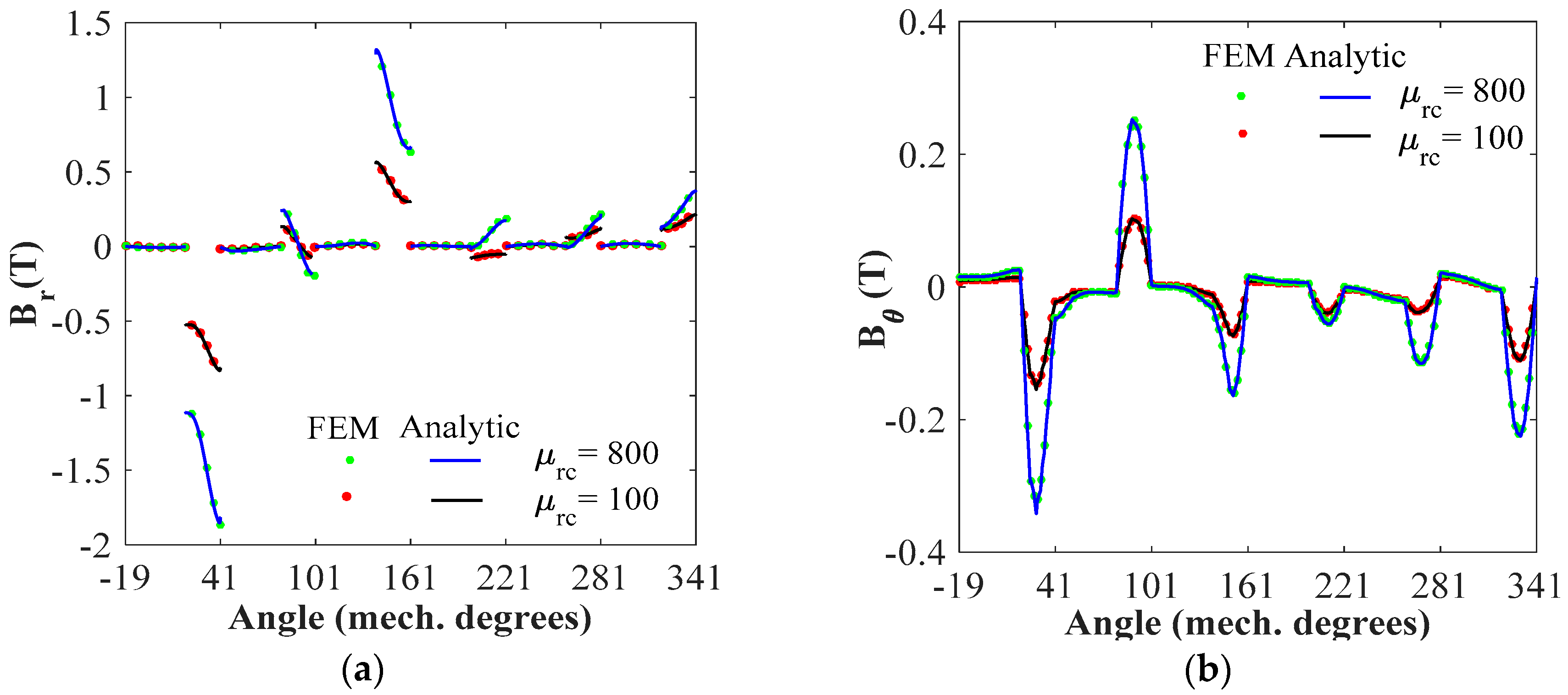
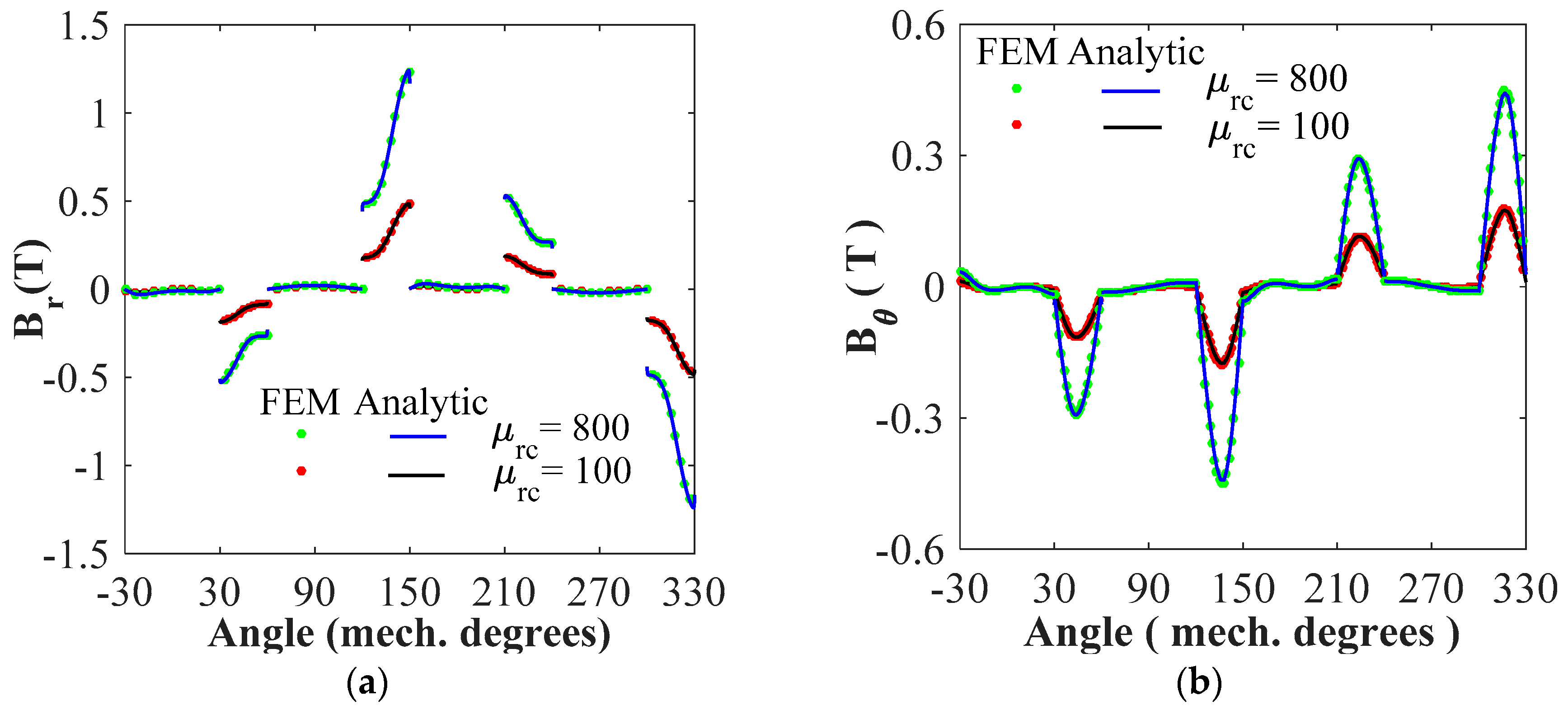
4. Results and Validations

The developed model (see Section 2) considering finite soft-magnetic material permeability is used to determine the magnetic flux density distribution inside the electrical machines as well as the electromagnetic performances for 6/4 SRM with two various non-overlapping (or concentrated) windings. The main dimensions and parameters of studied machines are given in Table 1. The results of the semi-analytical model are verified by 2D FEM.

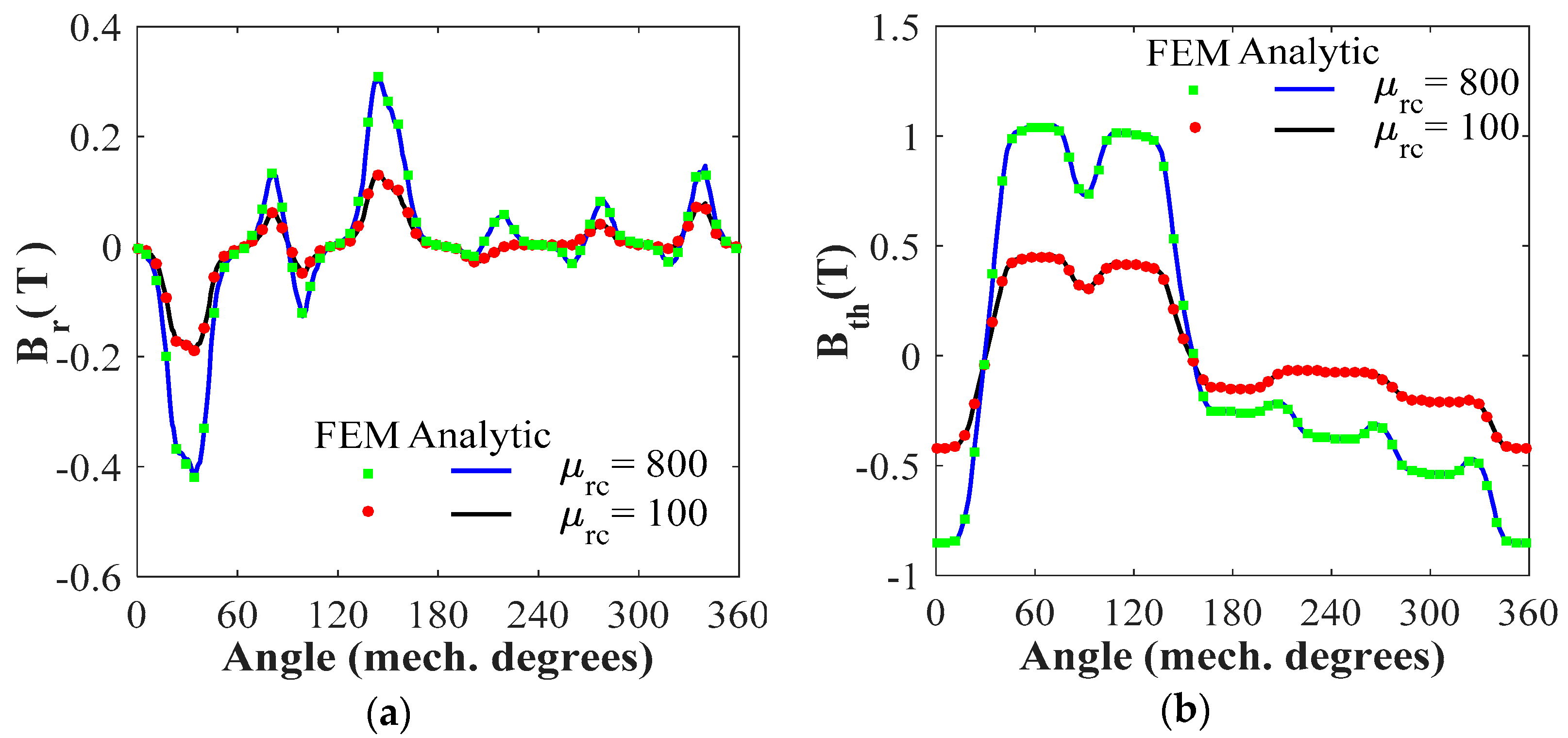
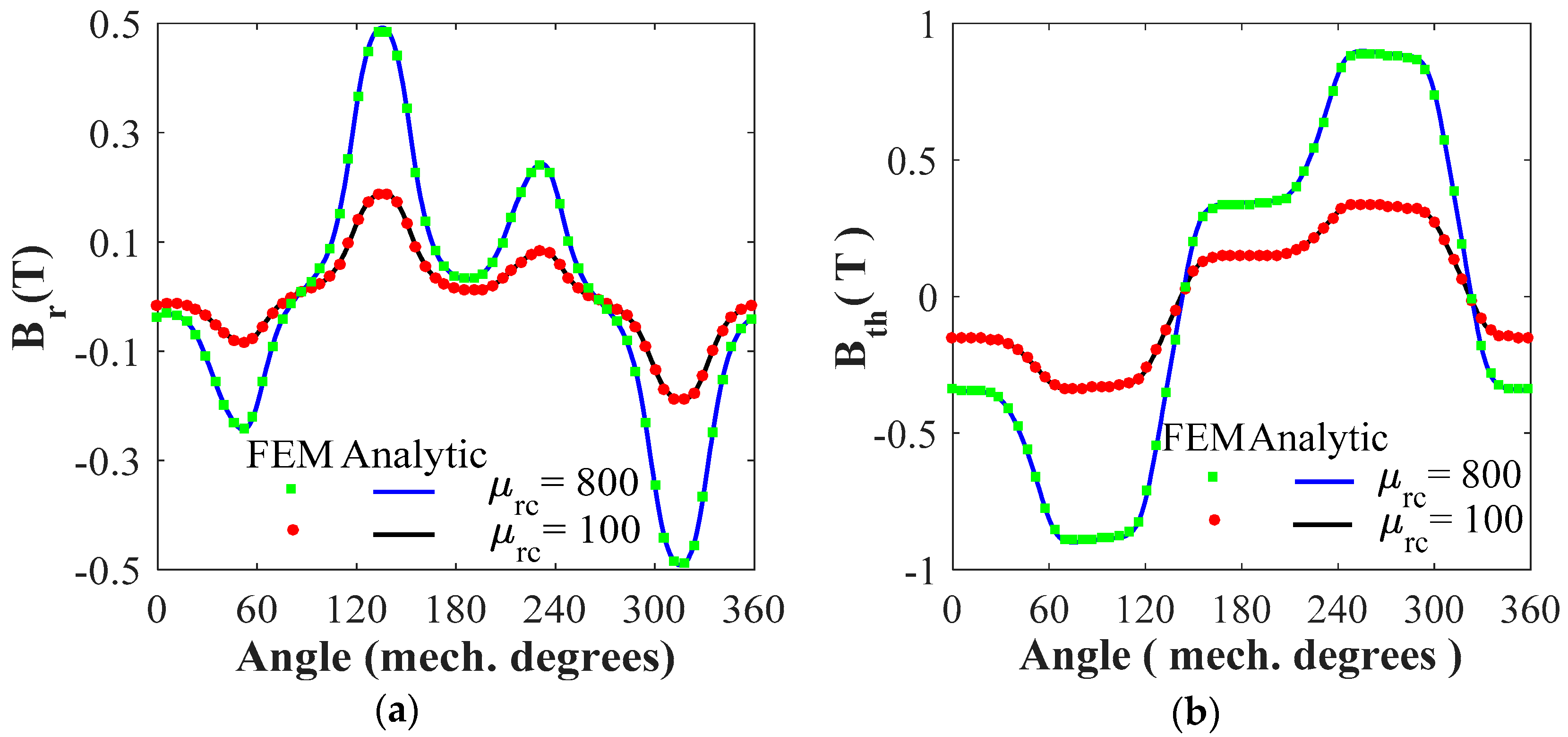
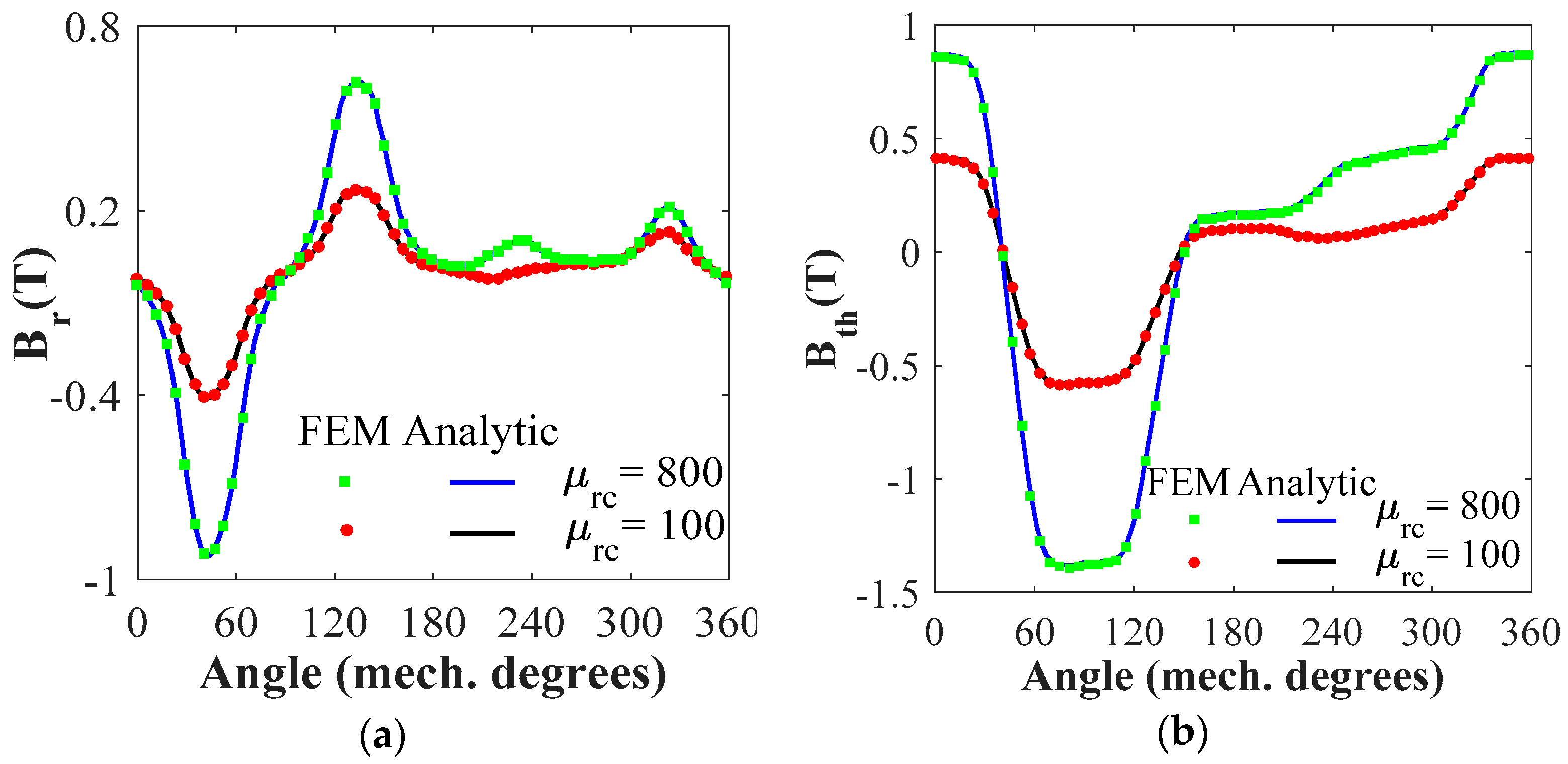
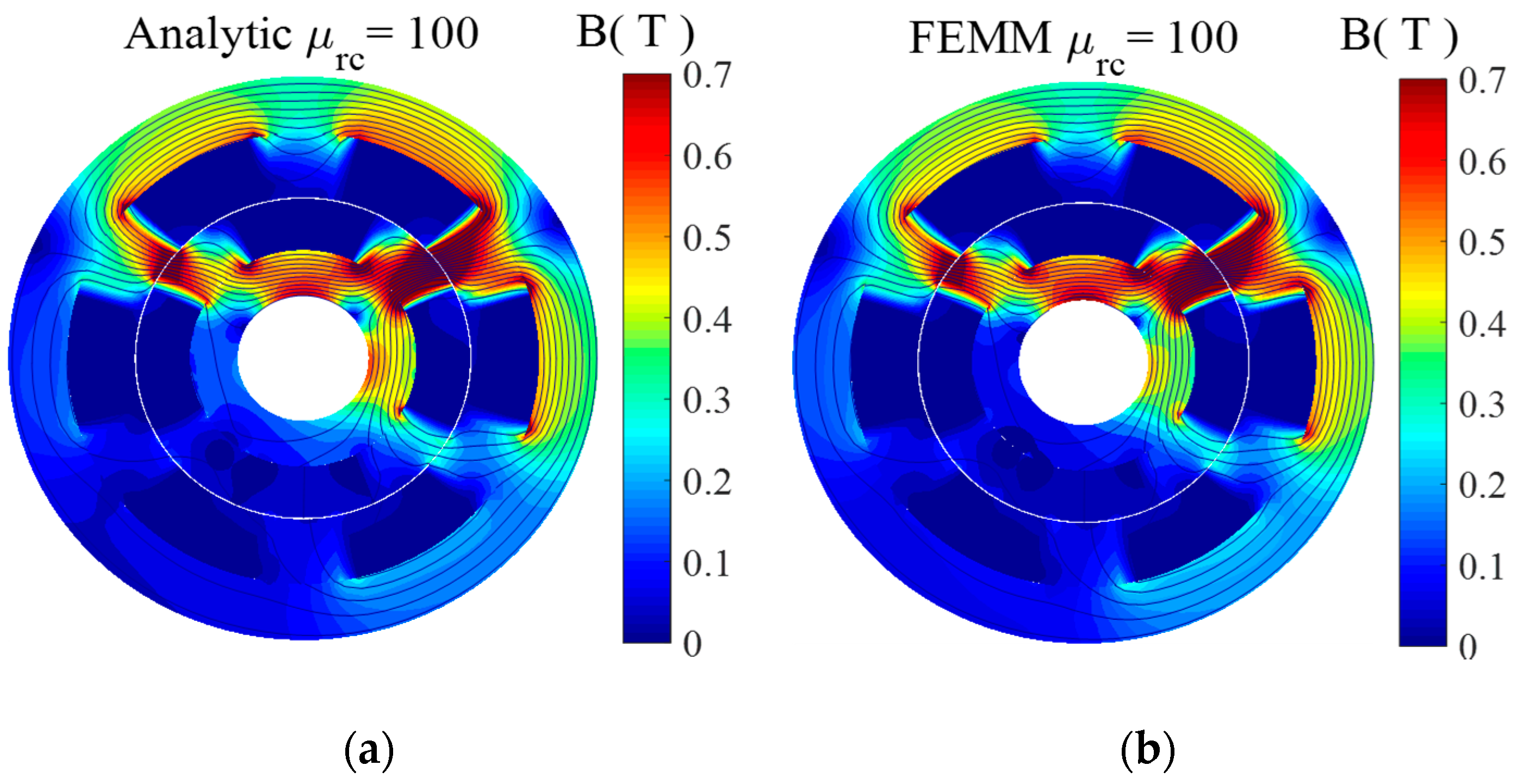
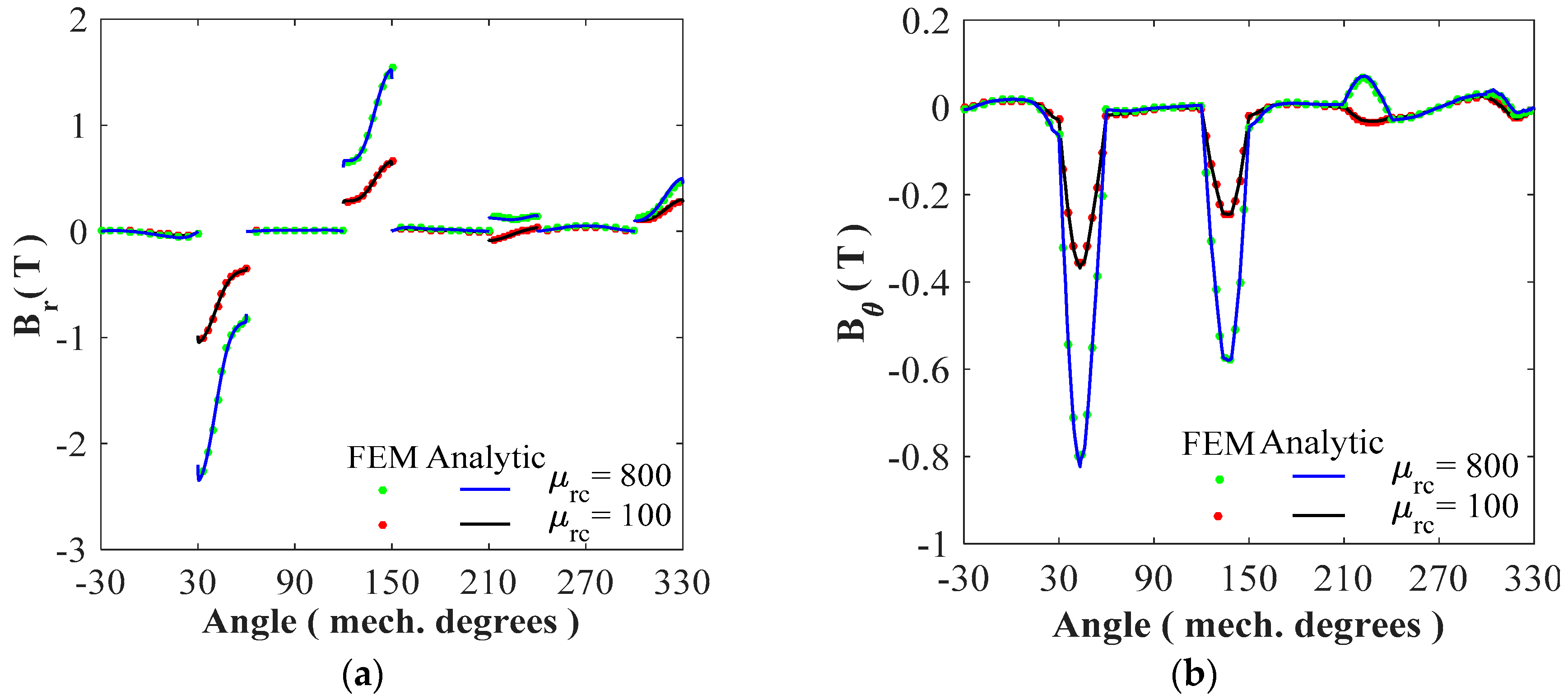
4.1. Magnetic Flux Density Distribution

The waveforms of r- and θ-components of the magnetic flux density in the various regions are computed with a finite number of harmonic terms, viz., N = 200 and M = K = 30 . The analytic calculation of magnetic flux density distribution in all regions is done considering the same relative permeability in all iron parts (i.e., stator/rotor yoke and teeth). The soft magnetic material permeability is constant corresponding to the linear zone of the B(H) curve. However, it is possible to use a different relative permeability value for each region [28,33,36].
In Figure 4 and Figure 5, a comparison between the numerical results and semi-analytical predictions is shown the r- and θ-components of B in the air gap middle (i.e., Region I at R g = ( R 4 + R 3 ) / 2 ) for two studied SRMs (i.e., M1 and M2). The simulations are done for two different values of iron core relative permeability (viz., 100 and 800). It can be seen an asymmetric distribution in the r- and θ-component of the air gap magnetic flux density in M2 in contrary to M1, this is due to the diametrically asymmetric disposition of slots and phase windings as shown in Figure 1b.
Figure 6 and Figure 7 show the magnitude of B in all machine’s regions for two studied SRMs (i.e., M1 and M2), we can notice that M2 is more saturated than M1.
In Figure 8, Figure 9, Figure 10, Figure 11, Figure 12, Figure 13, Figure 14 and Figure 15, for two studied SRMs (i.e., M1 and M2), a numerical and semi-analytical comparison is shown the r- and θ-components of B in the
The simulations were done for both values of iron core relative permeability. One can see that a very good agreement is obtained for the various components of B in all regions.

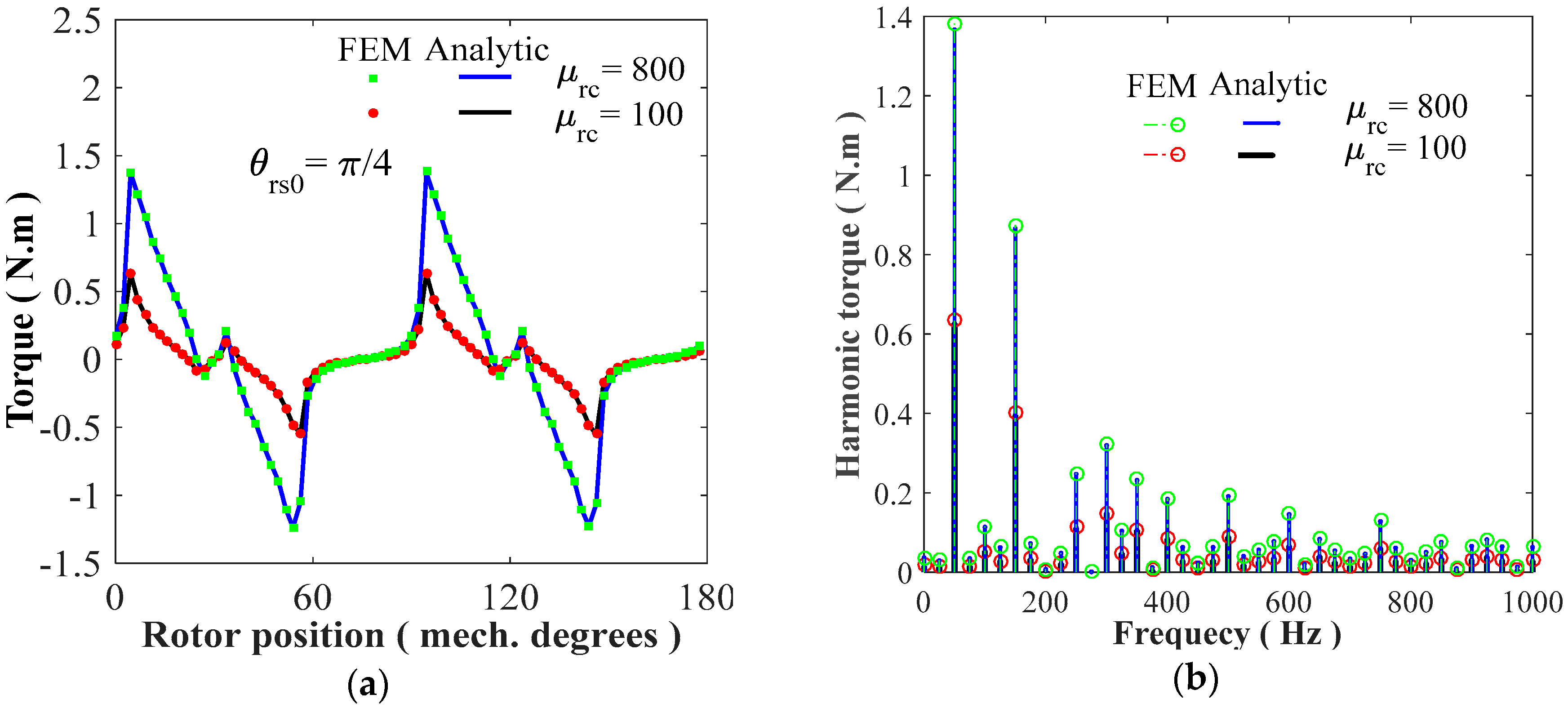
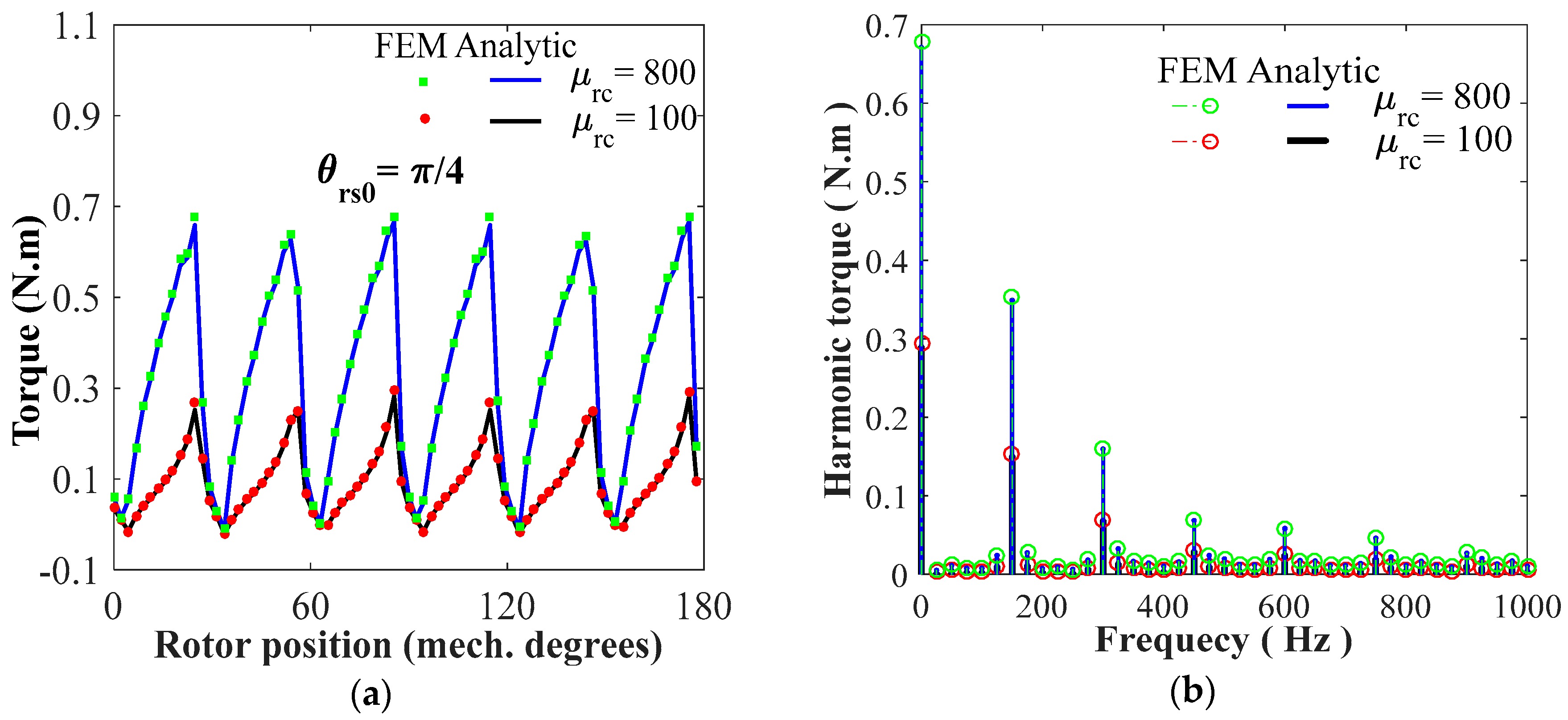
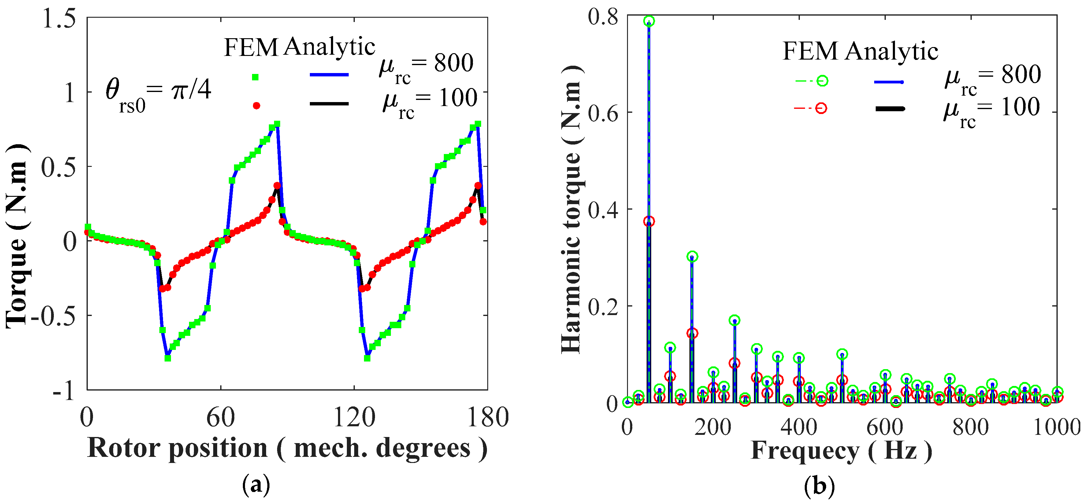
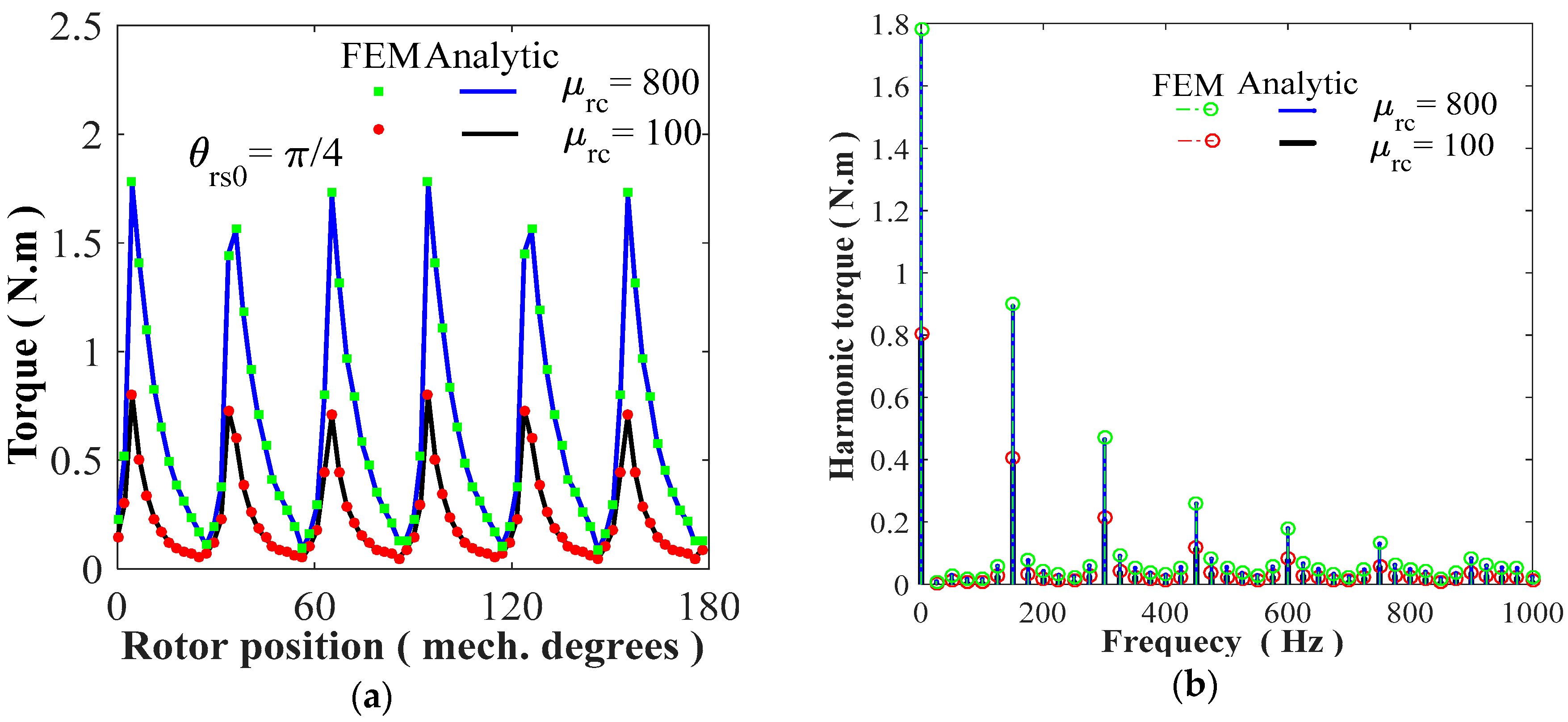
4.2. Static/Dynamic Electromagnetic Torques

For two studied SRMs (i.e., M1 and M2) and for both values of iron core relative permeability, Figure 16, Figure 17, Figure 18 and Figure 19 show the waveform as well as the harmonic spectrum of the static/dynamic electromagnetic torques for full-load condition (viz., 15 A @ 1500 rpm). The static electromagnetic torque represents the torque due to a single phase of the electrical machine (e.g., due to phase A). The dynamic electromagnetic torque represents the torque when the three phases are powered or due to the combination of three static electromagnetic torques. The good agreement between the results from 2D FEM and the proposed semi-analytical model can be seen. It is interesting to note that the ripple torques are more important for M2 (see Figure 19) with the same operating point.

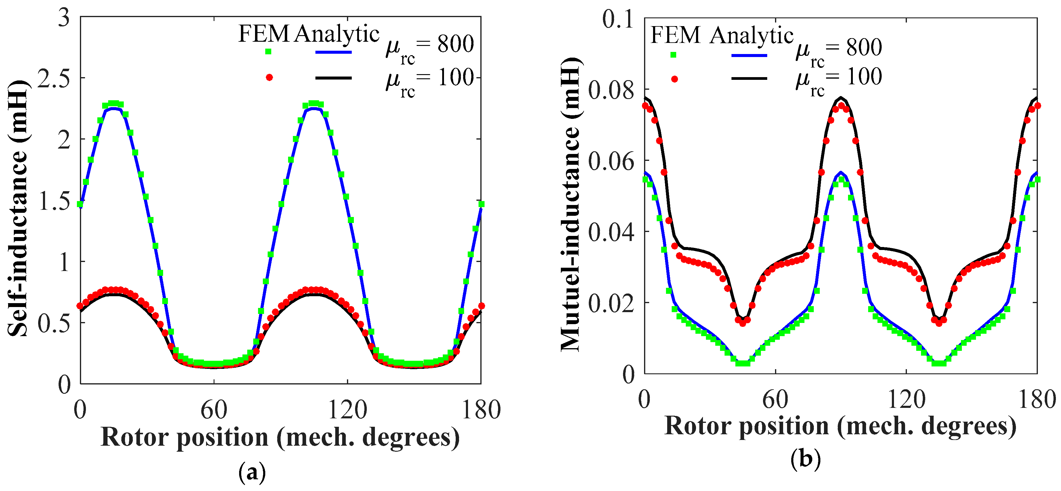
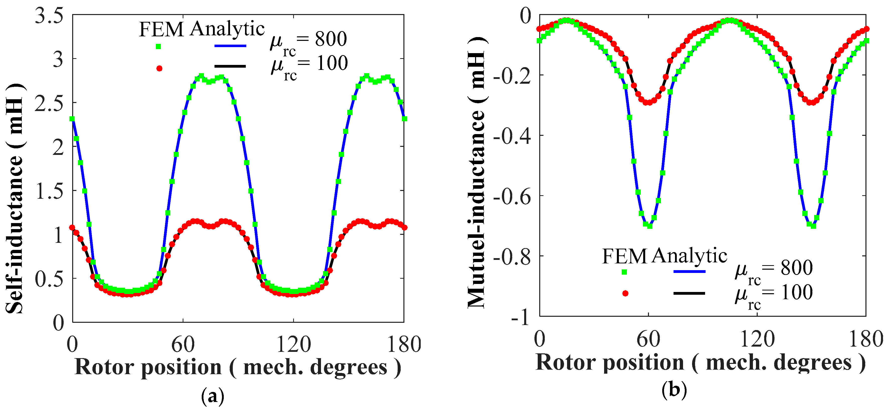
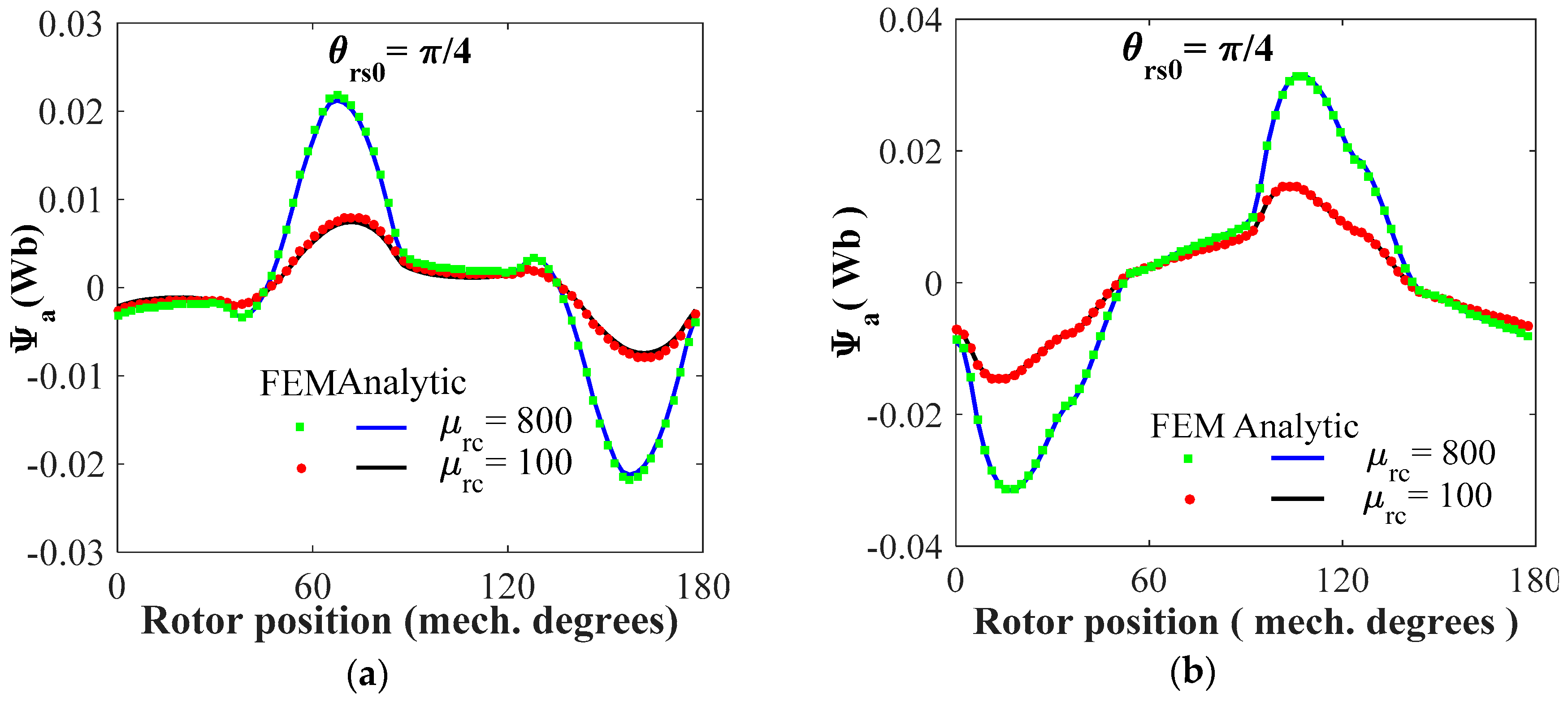
4.3. Magnetic Flux Linkage and Self-/Mutual Inductances

For full-load condition (viz., 15 A @ 1500 rpm), the induced magnetic flux linkage per phase of two studied SRMs (i.e., M1 and M2) are given in Figure 20. The simulations were done for both values of iron core relative permeability.
Figure 21 and Figure 22 show the self- and mutual inductance for M1 and M2, respectively; the simulation is done for nominal current. One can see that the self-inductance is slightly more important, while the mutual inductance is a much more important and negative value for M2. The obtained results confirm the accuracy of the proposed semi-analytical model, considering both amplitude and waveform.

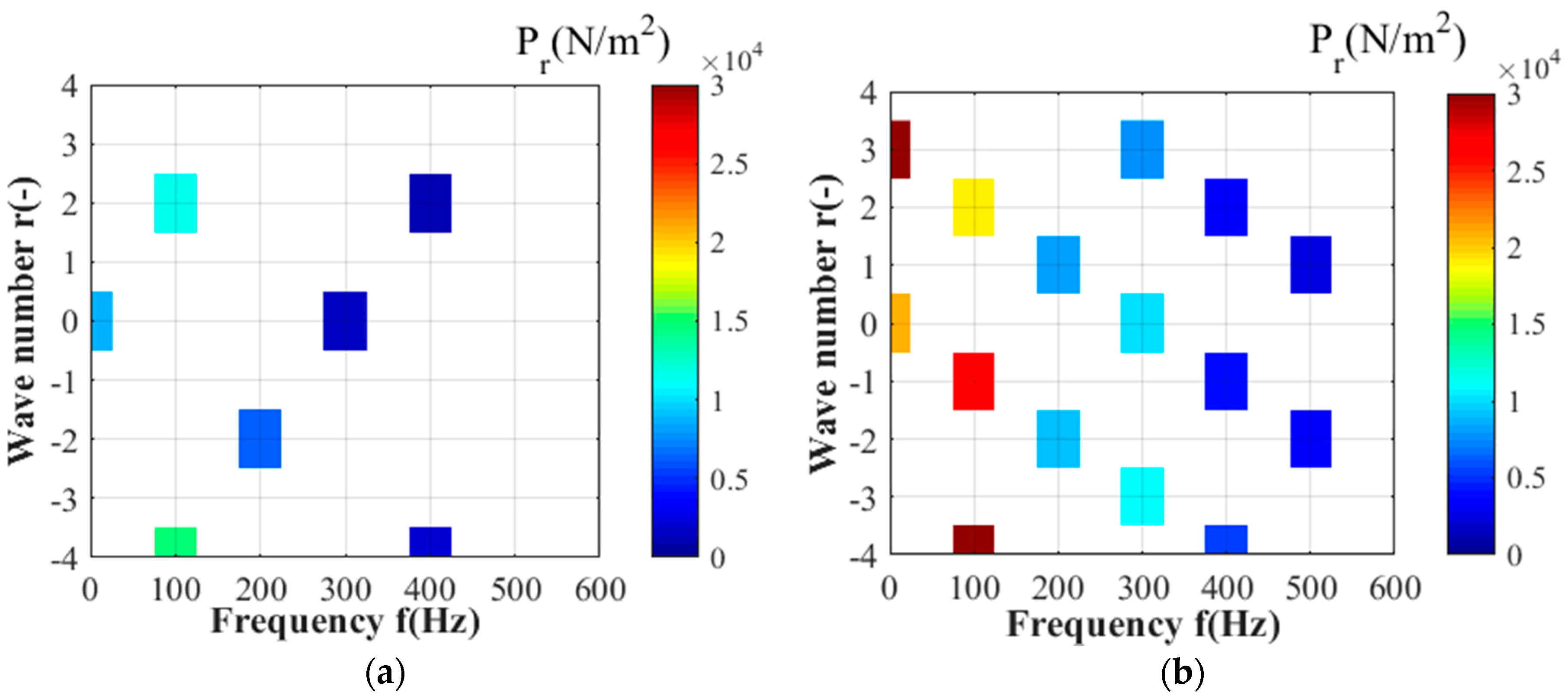
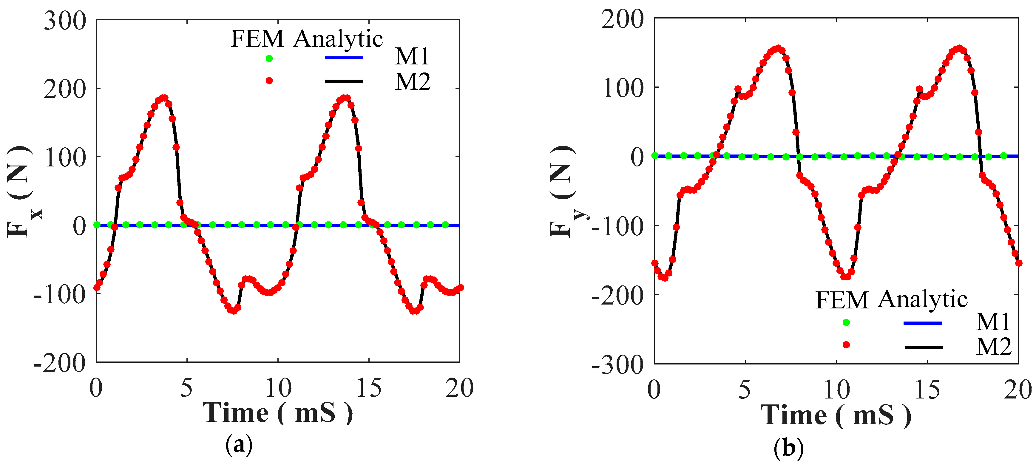
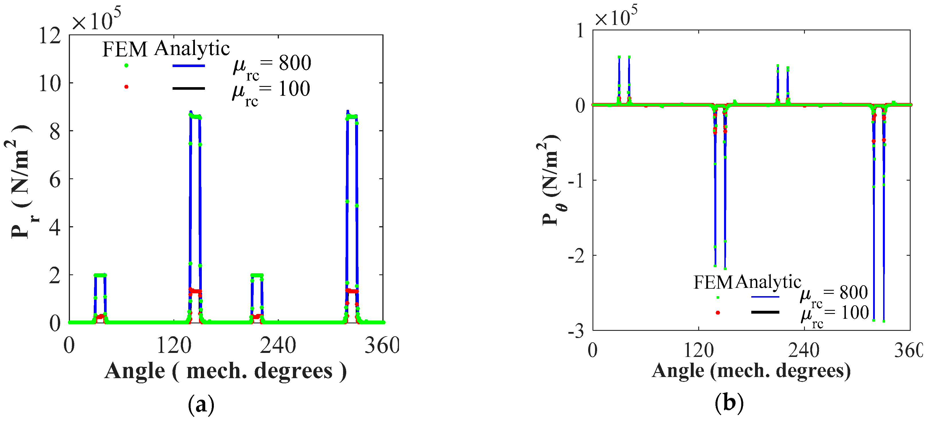
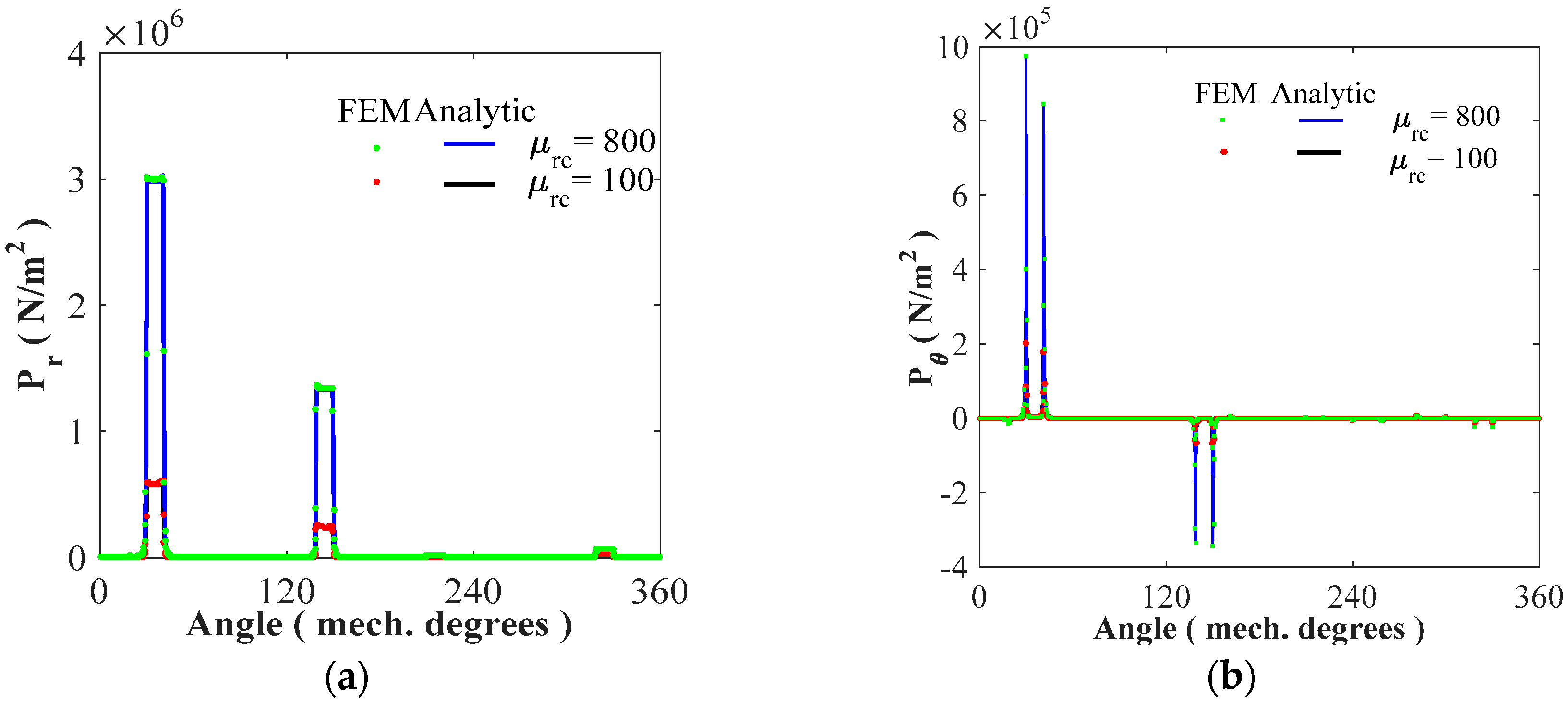
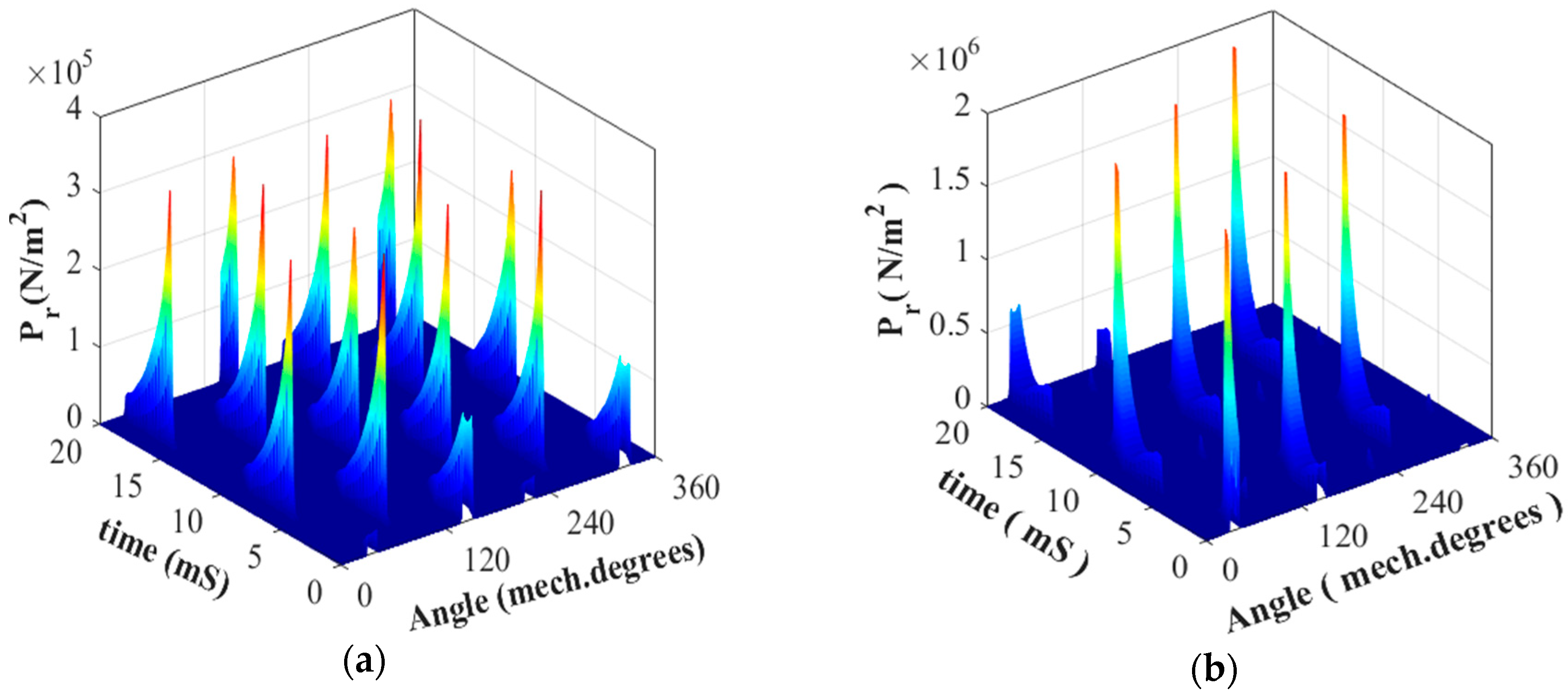
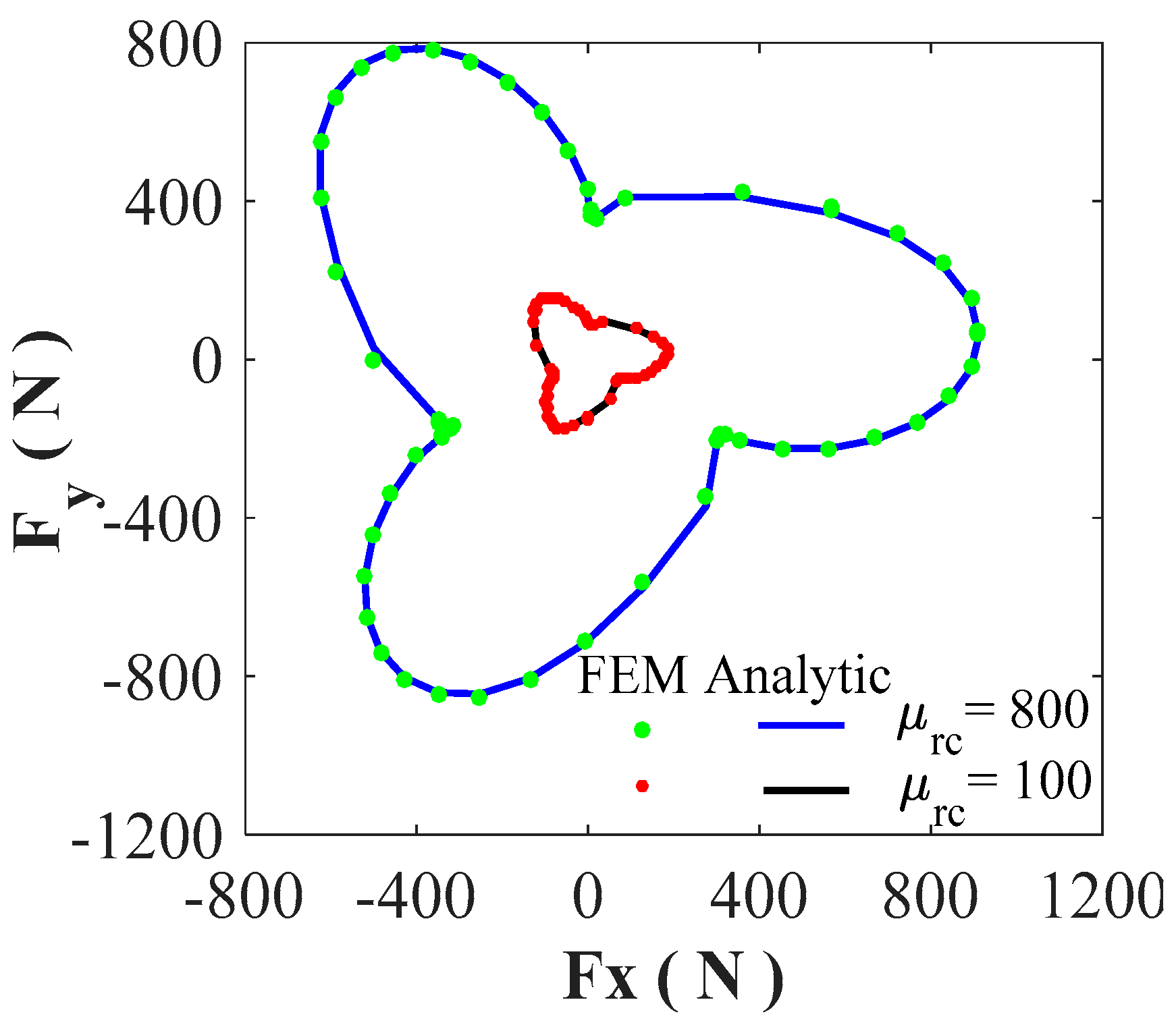
4.4. Magnetic Pressure and Non-Intrinsic UMFs

Figure 23 and Figure 24 show the r- and θ-components of P in function of space angle for the two studied SRMs (i.e., M1 and M2) and both values of iron core relative permeability. The analytical radial magnetic pressure in function of temporal rotor angle and the spatial angle is represented in Figure 25 for a no-load condition. Figure 26 shows the fast Fourier transform in 2D (FFT2D) of analytical radial magnetic pressure P r for M1 and M2. The x- and y-components of F in M1 and M2, for a no-load condition, are shown in Figure 27. It is clear that the non-intrinsic UMFs can be significant in SRMs, having diametrically asymmetric disposition of non-overlapping winding and due to the asymmetric magnetic field distribution in the air gap (see Figure 5).
The UMFs in M1 are null due to the proper choice of the armature winding type in the stator with same phase windings in diametrically opposite slots (see Figure 1a). Figure 28 shows the locus of the non-intrinsic UMF in M2. It is interesting to note that the UMFs and the magnetic pressures increases with the increase of the iron core relative permeability. One can see that the proposed semi-analytical model taking into account the iron core relative permeability gives good results compared to FEM.
The obtained results confirm the previous interpretation of the UMF. The component of the mode shapes one correspond to the wave number (i.e., r = 1 ) of the UMF does not appear in M1 due to the symmetric distribution of the air gap magnetic field with respect to the space angle p, contrary to M2. The component corresponds to the wave number (i.e., r = 2 ) is appeared in both SRMs, because of the asymmetric distribution magnetic field in the air gap with respect to the space angle p / 2 , as seen in Figure 4 and Figure 5. Moreover, it can be seen that the other modes that appeared in the two SRMs are multiples of the least non-null wave number r min = 1 in M2 and r min = 2 in M1.

5. Conclusions

In this paper, we have developed a 2D exact subdomain technique in polar coordinates considering the iron relative permeability for SRM supplied by a sinusoidal waveform of the current (aka, variable flux reluctance machines). This semi-analytical model, based on the scientific works of [24,33], predicts the magnetic flux density distribution inside the electrical machine as well as the electromagnetic performances. It has been applied to 6/4 SRM with two various non-overlapping (or concentrated) windings. These two configurations of non-overlapping winding have been considered to show their effect on the UMFs. Moreover, the spectrum of UMF permit us to study the effect of each harmonic on the vibrations of these machines. However, this research proved that the SRM with an asymmetric disposition of winding is more prone to higher levels of vibration than the SRM with a symmetric disposition due to the UMFs’ presence, which is the main source of vibration and acoustic noise. All results confirmed the accuracy of the proposed model. It can be considered a reliable alternative to FEM for analysis of SRMs.

Author Contributions

The work presented here was a cooperative effort by all the authors.

Conflicts of Interest

The authors declare no conflict of interest.

References

  1. Radimov, N.; Ben-Hail, N.; Rabinovici, R. Switched reluctance machines as three-phase AC autonomous generator. IEEE Trans. Magn. 2006, 42, 3760–3764. [Google Scholar] [CrossRef]
  2. Cheng, H.; Chen, H.; Yang, Z. Design indicators and structure optimisation of switched reluctance machine for electric vehicles. IET Electric Power Appl. 2015, 9, 319–331. [Google Scholar] [CrossRef]
  3. Takeno, M.; Chiba, A.; Hoshi, N.; Ogasawara, S.; Takemoto, M.; Rahman, A. Test results and torque improvement of the 50-kW switched reluctance motor designed for hybrid electric vehicles. IEEE Trans. Ind. Appl. 2012, 48, 1327–1334. [Google Scholar] [CrossRef]
  4. Li, G.J.; Ojeda, J.; Hlioui, S.; Hoang, E.; Lecrivain, M.; Gabsi, M. Modification in rotor pole geometry of mutually coupled switched reluctance machine for torque ripple mitigating. IEEE Trans. Magn. 2012, 48, 2025–2034. [Google Scholar] [CrossRef]
  5. Lawrenson, P.J.; Stephenson, J.M.; Blenkinsop, P.T.; Korda, J.; Fulton, N.N. Variable-speed switched reluctance motors. IEE Proc. B Electric Power Appl. 1980, 127, 253–265. [Google Scholar] [CrossRef]
  6. Sahin, C.; Amac, A.E.; Karacor, M.; Emadi, A. Reducing torque ripple of switched reluctance machines by relocation of rotor moulding clinches. IET Electric Power Appl. 2012, 6, 753–760. [Google Scholar] [CrossRef]
  7. Lin, C.; Fahimi, B. Prediction of acoustic noise in switched reluctance motor drives. IEEE Trans. Energy Convers. 2014, 29, 250–258. [Google Scholar] [CrossRef]
  8. Lee, D.H.; Pham, T.H.; Ahn, J.W. Design and operation characteristics of four-two pole high-speed SRM for torque ripple reduction. IEEE Trans. Ind. Electron. 2013, 60, 3637–3643. [Google Scholar] [CrossRef]
  9. Husain, I.; Radun, A.; Nairus, J. Unbalanced force calculation in switched reluctance machines. IEEE Trans. Magn. 2000, 36, 330–338. [Google Scholar] [CrossRef]
  10. Shen, L.; Wu, J. Switched reluctance motor vibration prediction: From low frequency to high frequency. In Proceedings of the IEMDC, Miami, FL, USA, 3–6 May 2009. [Google Scholar]
  11. Gieras, J.F.; Lai, J.C.; Wang, C. Noise of Polyphase Electric Motors; CRC/Taylor & Francis: Boca Raton, FL, USA, 2006. [Google Scholar]
  12. Lin, C.; Fahimi, B. Prediction of radial vibration in switched reluctance machines. IEEE Trans. Energy Convers. 2013, 28, 1072–1081. [Google Scholar] [CrossRef]
  13. Zhu, Z.Q.; Ishak, D.; Howe, D.; Chen, J. Unbalanced magnetic forces in permanent-magnet brushless machines with diametrically asymmetric phase windings. IEEE Trans. Ind. Appl. 2007, 43, 1544–1553. [Google Scholar] [CrossRef]
  14. Boughrara, K.; Ibtiouen, R.; Dubas, F. Analytical prediction of electromagnetic performances and unbalanced magnetic forces in fractional-slot spoke-type permanent-magnet machines. In Proceedings of the ICEM, Lausanne, Switzerland, 4–7 September 2016. [Google Scholar]
  15. Yilmaz, M.; Krein, P.T. Capabilities of finite element analysis and magnetic equivalent circuits for electrical machine analysis and design. In Proceedings of the PESC, Rhodes, Greece, 15–19 June 2008. [Google Scholar]
  16. Dubas, F.; Espanet, C. Analytical solution of the magnetic field in permanent-magnet motors taking into account slotting effect: No-load vector potential and flux density calculation. IEEE Trans. Magn. 2009, 45, 2097–2109. [Google Scholar] [CrossRef]
  17. Zhu, Z.Q.; Wu, L.J.; Xia, Z.P. An accurate subdomain model for magnetic field computation in slotted surface-mounted permanent-magnet machines. IEEE Trans. Magn. 2010, 46, 1100–1115. [Google Scholar] [CrossRef]
  18. Tiegna, H.; Amara, Y.; Barakat, G. Overview of analytical models of permanent magnet electrical machines for analysis and design purposes. Math. Comput. Simul. 2013, 90, 162–177. [Google Scholar] [CrossRef]
  19. Dubas, F.; Rahideh, A. Two-dimensional analytical permanent-magnet eddy-current loss calculations in slotless PMSM equipped with surface-inset magnets. IEEE Trans. Magn. 2014, 50, 54–73. [Google Scholar] [CrossRef]
  20. Curti, M.; Paulides, J.J.H.; Lomonova, E.A. An overview of analytical methods for magnetic field computation. In Proceedings of the EVER, Grimaldi Forum, Monte Carlo, Monaco, 31 March–2 April 2015. [Google Scholar]
  21. Sprangers, R.L.J.; Paulides, J.J.H.; Gysen, B.L.J.; Lomonova, E.A. Magnetic saturation in semi-analytical harmonic modeling for electric machine analysis. IEEE Trans. Magn. 2016, 52, 1–10. [Google Scholar] [CrossRef]
  22. Pfister, P.-D.; Yin, X.; Fang, Y. Slotted permanent-magnet machines: General analytical model of magnetic fields, torque, eddy currents, and permanent-magnet power losses including the diffusion effect. IEEE Trans. Magn. 2016, 52, 1–13. [Google Scholar] [CrossRef]
  23. Devillers, E.; Besnerais, J.L.; Lubin, T.; Hecquet, M.; Lecointe, J.-P. A review of subdomain modeling techniques in electrical machines: Performances and applications. In Proceedings of the ICEM, Lausanne, Switzerland, 4–7 September 2016. [Google Scholar]
  24. Dubas, F.; Boughrara, K. New scientific contribution on the 2-D subdomain technique in Cartesian coordinates: Taking into account of iron parts. Math. Comput. Appl. 2017, 22, 17. [Google Scholar] [CrossRef]
  25. Boughrara, K.; Lubin, T.; Ibtiouen, R. General subdomain model for predicting magnetic field in internal and external rotor multiphase flux-switching machines topologies. IEEE Trans. Magn. 2013, 49, 5310–5325. [Google Scholar] [CrossRef]
  26. Dubas, F.; Boughrara, K. New scientific contribution on the 2-D subdomain technique in polar coordinates: Taking into account of iron parts. Math. Comput. Appl. 2017, 22, 42. [Google Scholar] [CrossRef]
  27. Roubache, L.; Boughrara, K.; Dubas, F.; Ibtiouen, R. Semi-analytical modeling of spoke-type permanent-magnet machines considering the iron core relative permeability: Subdomain technique and Taylor polynomial. Prog. Electromagn. Res. B 2017, 77, 85–101. [Google Scholar] [CrossRef]
  28. Roubache, L.; Boughrara, K.; Dubas, F.; Ibtiouen, R. Semi-analytical modeling of spoke-type permanent-magnet machines considering nonlinear magnetic saturation: Subdomain technique and Taylor polynomial. Math. Comput. Simul. 2018. to be published. [Google Scholar]
  29. Sprangers, R.L.J.; Paulides, J.J.H.; Gysen, B.L.J.; Waarma, J.; Lomonova, E.A. Semi-analytical framework for synchronous reluctance motor analysis including finite soft-magnetic material permeability. IEEE Trans. Magn. 2015, 51, 1–4. [Google Scholar] [CrossRef]
  30. Ramakrishnan, K.; Curti, M.; Zarko, D.; Mastinu, G.; Paulides, J.J.H.; Lomonova, E.A. Comparative analysis of various methods for modelling surface permanent magnet machines. IET Electric Power Appl. 2017, 11, 540–547. [Google Scholar] [CrossRef]
  31. Djelloul, K.Z.; Boughrara, K.; Dubas, F.; Kechroud, A.; Souleyman, B. Semi-analytical magnetic field predicting in many structures of permanent-magnet synchronous machines considering the iron permeability. IEEE Trans. Magn. 2018, 54, 8103921. [Google Scholar]
  32. Djelloul, K.Z.; Boughrara, K.; Ibtiouen, R.; Dubas, F. Nonlinear analytical calculation of magnetic field and torque of switched reluctance machines. In Proceedings of the CISTEM, Marrakech, Morocco, 26–28 October 2016. [Google Scholar]
  33. Djelloul, K.Z.; Boughrara, K.; Dubas, F.; Ibtiouen, R. Nonlinear analytical prediction of magnetic field and electromagnetic performances in switched reluctance machines. IEEE Trans. Magn. 2017, 53, 1–11. [Google Scholar] [CrossRef]
  34. Roubache, L.; Boughrara, K.; Dubas, F.; Ibtiouen, R. New subdomain technique for electromagnetic performances calculation in radial-flux electrical machines considering finite soft-magnetic material permeability. IEEE Trans. Magn. 2018, 54, 8103315. [Google Scholar] [CrossRef]
  35. Boughrara, K.; Dubas, F.; Ibtiouen, R. 2-D exact analytical method for steady-state heat transfer prediction in rotating electrical machines. IEEE Trans. Magn. 2018, 54, 1–19. [Google Scholar] [CrossRef]
  36. Roubache, L.; Boughrara, K.; Dubas, F.; Ibtiouen, R. Elementary subdomain technique for magnetic field calculation in rotating electrical machines with local saturation effect. Int. J. Comput. Math. Electr. Electron. Eng. 2018. [Google Scholar] [CrossRef]
  37. Hannon, B.; Sergeant, P.; Dupré, L. Two-dimensional Fourier-based modeling of electric machines. In Proceedings of the IEMDC, Miami, FL, USA, 21–24 May 2017. [Google Scholar]
  38. Meeker, D.C. Finite Element Method Magnetics ver. 4.2. Available online: www.femm.info/wiki/download (accessed on 10 October 2018).
  39. Ouamara, D.; Dubas, F.; Benallal, M.N.; Randi, S.A.; Espanet, C. Automatic winding generation using matrix representation—ANFRACTUS TOOL 1.0. Acta Polytech. 2018, 58, 37–46. [Google Scholar] [CrossRef]
  40. Islam, R.; Husain, I. Analytical model for predicting noise and vibration in permanent-magnet synchronous motors. IEEE Trans. Ind. Appl. 2010, 46, 2346–2354. [Google Scholar] [CrossRef]
Figure 1. Studied 6/4 SRM with sinusoidal current excitation having a non-overlapping (or concentrated) winding, viz., (a) M1: all teeth wound (double-layer winding with left and right layer), and (b) M2: alternate teeth wound (single-layer winding).
Mca 23 00059 g001
Figure 2. Simplified model of SRM.
Mca 23 00059 g002
Figure 3. Flowchart of subdomain technique.
Mca 23 00059 g003
Figure 4. Waveform of the magnetic flux density in the air gap middle (i.e., Region I) for M1: (a) r- and (b) θ-component.
Mca 23 00059 g004
Figure 5. Waveform of the magnetic flux density in the air gap middle (i.e., Region I) for M2: (a) r- and (b) θ-component.
Mca 23 00059 g005
Figure 6. Flux density inside the machine in M1: (a) analytic and (b) FEM.
Mca 23 00059 g006
Figure 7. Flux density inside the machine in M2: (a) analytic and (b) FEM.
Mca 23 00059 g007
Figure 8. Waveform of the magnetic flux density in the stator yoke middle for M1: (a) r- and (b) θ-component.
Mca 23 00059 g008
Figure 9. Waveform of the magnetic flux density in the stator yoke middle for M2: (a) r- and (b) θ-component.
Mca 23 00059 g009
Figure 10. Waveform of the magnetic flux density in the rotor yoke middle for M1: (a) r- and (b) θ-component.
Mca 23 00059 g010
Figure 11. Waveform of the magnetic flux density in the rotor yoke middle for M2: (a) r- and (b) θ-component.
Mca 23 00059 g011
Figure 12. Waveform of the magnetic flux density in the stator slots/non-periodic air gap/teeth for M1: (a) r- and (b) θ-component.
Mca 23 00059 g012
Figure 13. Waveform of the magnetic flux density in the stator slots/non-periodic air gap/teeth for M2: (a) r- and (b) θ-component.
Mca 23 00059 g013
Figure 14. Waveform of the magnetic flux density in the rotor slots/teeth for M1: (a) r- and (b) θ-component.
Mca 23 00059 g014
Figure 15. Waveform of the magnetic flux density in the rotor slots/teeth for M2: (a) r- and (b) θ-component.
Mca 23 00059 g015
Figure 16. The static electromagnetic torque due to phase-A for M1: (a) waveform; (b) harmonic spectrum.
Mca 23 00059 g016
Figure 17. The static electromagnetic torque due to phase-A for M2: (a) waveform; (b) harmonic spectrum.
Mca 23 00059 g017
Figure 18. The dynamic electromagnetic torque (for full-load condition) for M1: (a) waveform; (b) harmonic spectrum.
Mca 23 00059 g018
Figure 19. The dynamic electromagnetic torque (for full-load condition) for M2: (a) waveform; (b) harmonic spectrum.
Mca 23 00059 g019
Figure 20. Waveform of the magnetic flux linkage at full-load condition (15 A @ 1500 rpm) for θrs0 = π/Qr in (a) M1 and (b) M2.
Mca 23 00059 g020
Figure 21. Waveform of the (a) self- and (b) mutual inductance for M1.
Mca 23 00059 g021
Figure 22. Waveform of the (a) self- and (b) mutual inductance for M2.
Mca 23 00059 g022
Figure 23. Waveform of magnetic pressures (for no-load condition) in M1: (a) r- and (b) θ-component.
Mca 23 00059 g023
Figure 24. Waveform of the magnetic pressures (for no-load condition) in M2: (a) r- and (b) θ-component.
Mca 23 00059 g024
Figure 25. Analytical radial magnetic pressure versus time and space angle (for no-load condition) in (a) M1 and (b) M2.
Mca 23 00059 g025
Figure 26. Analytical radial magnetic pressure with FFT2D for no-load condition in (a) M1 and (b) M2.
Mca 23 00059 g026
Figure 27. Waveform of UMFs (for no-load condition) in the two studied SRMs (i.e., M1 and M2): (a) x- and (b) y-component.
Mca 23 00059 g027
Figure 28. Locus of the non-intrinsic UMF in M2 for no-load condition.
Mca 23 00059 g028
Table 1. Parameters of the studied SRMs.
Parameters, Symbols [Units]Values
M1 Double LayerM2 Single Layer
Winding distributionConcentrated
Number of stator slots, Qs [-]6
Number of rotor poles, Qr [-]4
Radius of the external stator surface, Rext [mm]45
External radius of stator slot, R5 [mm]36
Radius of the internal stator surface, R4 [mm]25.7
Radius of the rotor surface, R3 [mm]25.5
Internal radius of rotor slot, R2 [mm]17.3
Radius of the shaft, R1 [mm]10
Air gap thickness, g [mm]0.2
Axial length of the machine, Lu [mm]60
Rotor slot-opening, a [deg.]60
Rotor tooth-opening, b [deg.]30
Stator slot opening, c [deg.]38
Stator tooth opening, d [deg.]22
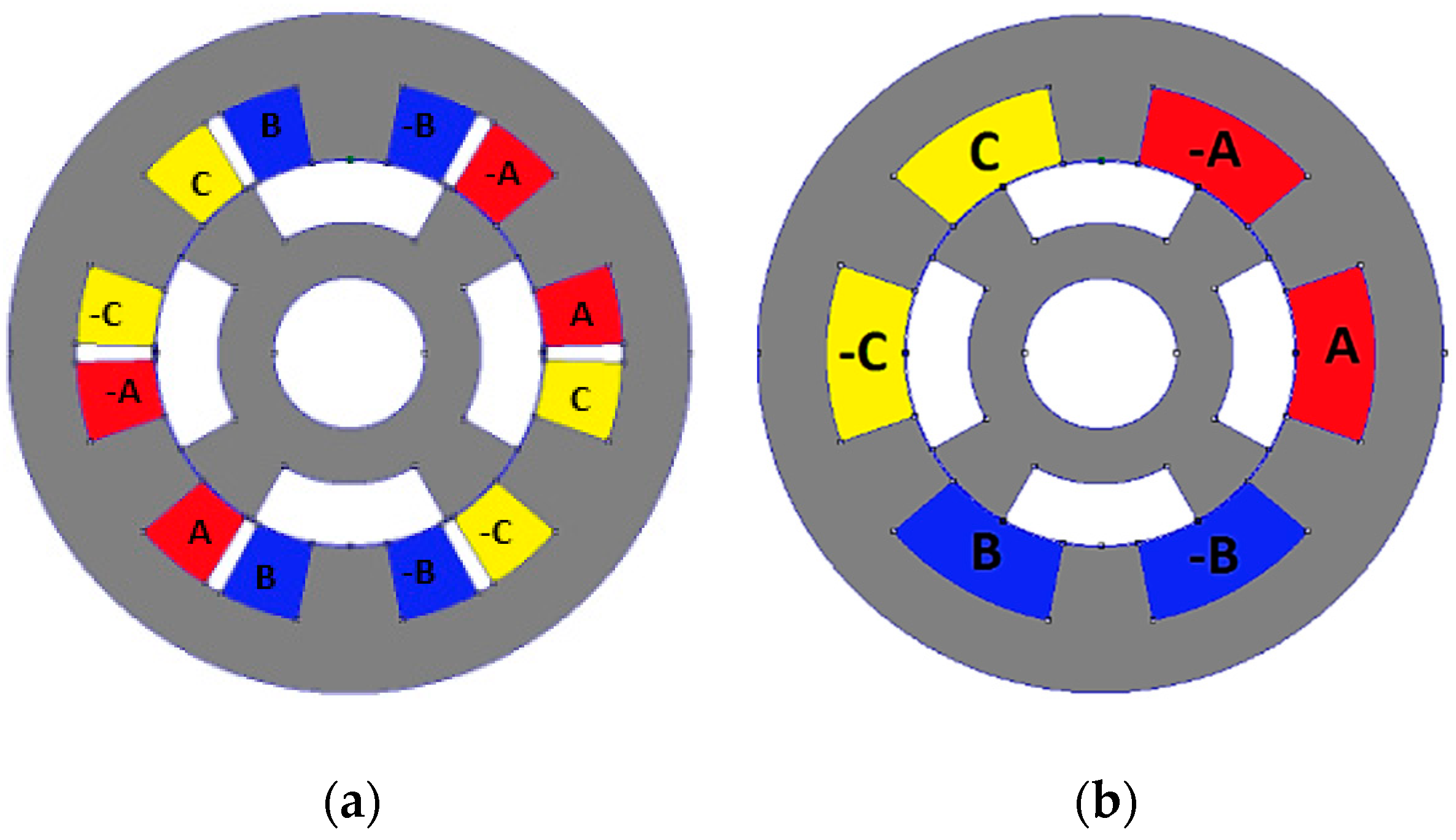
Non-periodic air gap (i.e., between the two-layer winding of stator slots) opening, e [deg.]40
Opening of a slot coil, f [deg.]1738
Number of conductor of slot coil, Nc [-]2040
Phase current, I [A]15
Current density of the coil, J [A/mm²]3.18

