Abstract
Microdevices have been actively implemented in chemical processes, such as in mixing and reactions. However, microseparation devices, excluding extraction devices, are still under development. In distillation, the use of microdevices has been expected to improve separation performance, as their large specific surface area enables a rapid vapor–liquid equilibrium and for large temperature gradients to be easily realized. In this study, improvements in throughput and product purities in microdistillation devices were achieved for ethyl acetate–toluene distillation. At low feedstock flow rates, ethyl acetate was successfully purified to 99.5 wt%. Although the performance decreased with increasing feedstock flow rate, by increasing the channel length, this performance decrease was suppressed even at high flow rates. The thickness of the channel was also important, and the highest performance was observed at the lowest thickness of 0.5 mm. A performance evaluation using the HETP showed that the efficiency was seven times higher than that of conventional packed column distillators.
1. Introduction
In recent years, many studies have been conducted on microscale operations. Microdevices offer advantages such as exhibiting rapid heat transfer and mass transfer, which are derived from their narrow flow path and high specific surface area, precise control of the residence time, and improved safety. In particular, there are many reports on device development, including reactors, mixers, and pumps [1,2,3,4]. There are also a wide variety of reports on reaction operations [5,6], especially mixing, that take advantage of the tiny mixing space in micro-devices and the resulting short diffusion distance [7]. However, most of these reports focus on separation and specifically on extraction [8,9,10]. This occurs because the use of microfluidic channels enables flow states that are difficult to realize on a macroscopic scale, such as the realization of emulsions, lamellar flows, and slug flows. All of these unique flow states maintain a large contact interfacial area between phases, which is very useful for an extraction operation. For example, in a slug flow, multiple immiscible fluids flow alternately in the channel. In this process, an internal circulation flow is generated in each slug, and the concentration in the slug becomes uniform. As a result, the accumulation of extracted components at the interface is suppressed, enabling extraction operations with a large driving force (i.e., concentration difference) and a large interfacial area. In emulsions, significantly large contact interfacial areas are achieved, increasing the efficiency of mass transfer between the emulsion phases. In lamellar flow, contact in a microchannel can achieve a large contact interfacial area between the fluids while maintaining a regular flow regime in a channel. These features are expected to be utilized not only in extraction but also in distillation, which is one of the very important separation operations, yet there are fewer reported cases about microdistillation compared to extraction. In one previous case, Timmer et al. implemented a distillation operation using a microdevice equipped with a membrane [11]. An aqueous NaCl solution was brought into contact with a membrane installed in a microfluidic channel. On the permeate side, a countercurrent flow of nitrogen gas swept out the permeating water vapor. The NaCl concentration of the solution at the outlet of the membrane channel was measured, and the performance of the device was discussed. The effects of the aqueous solution and nitrogen gas flow rates were examined, and the large contact area achieved by the membrane lead to highly efficient concentration. While a high selectivity and efficiency separation were expected with the introduction of these membranes, issues remain related to the manufacturing cost of these membranes and devices, along with the membrane’s stability. Hibara et al. fabricated a microdistillation device using electron beam lithography and plasma etching with fused silica [12]. The geometry of the device with micropillars was precisely designed, including the width, length, and angle, and organized sections, such as evaporation zones and condensation zones, were arranged to realize high performance. The device allowed a stable concentration operation of 9.0 wt% aqueous ethanol solution to 19 wt%, with a throughput of 2 μL/min at 78 °C. While a stable performance was obtained, high-manufacturing technology was required to fabricate complex structures in a small device. Boyd et al. studied a system employing laser irradiation in a microchannel [13]. The liquid phase near the gas–liquid interface in a microchannel was irradiated using a laser, and the vaporized components condensed a short distance away from the gas–liquid interface to form the liquid phase. This design ensured that only the vaporized components were collected as a pure solution at a distance. The biggest advantage of this system was its heating capability, which was localized and mild without being excessive. However, the system also did not realize high throughput and required precise operation. As an example of multicomponent distillation, Ziogas et al. fabricated a miniaturized rectangular distillation apparatus instead of a conventional cylindrical apparatus and separated several mixtures [14]. For example, a mixture of p-xylene and o-xylene, which have very similar boiling points, yielded a 68 mol% p-xylene solution as the distillate and 42 mol% as the remaining fluid. Taking advantage of the unique features of microdistillation devices, Hartman et al. reported a method that utilized a segmented flow of nitrogen carrier gas and feedstock liquid [15]. While the slug flow passed through the channel, the gas–liquid reached equilibrium, and the products were finally collected following gas–liquid separation. Methanol–toluene mixtures and dichloromethane–toluene mixtures were used as examples, and the results obtained were in good agreement with those obtained from the flash distillation with the vapor–liquid equilibrium diagram. Wootton et al. also examined distillation with carrier gas [16]. The equipment consisted of a gas–liquid contact section, a condensation section, and a separation section for the carrier gas and product. After the carrier gas and feedstock liquid made contact as a laminar parallel flow at the heated contact section, gas–liquid separation was performed, and the vapor–gas passed through the condensation section for subsequent gas–liquid separation. The separation of acetonitrile and dimethylformamide was performed as an example, and a separation performance of 0.72 as the number of plates at total reflux was obtained at a feedstock flow rate of 150 μL/min. One of the drawbacks evident in these methods was requiring carrier gas, which lead to further separation at the outlet. Furthermore, distillation in these concurrent flow operations was limited to a single theoretical plate, and the general disadvantage was the small throughput due to the microdevice. As a microdistillation device with a countercurrent flow, Sundberg et al. used a horizontally placed distillator, with one end heated and the other end cooled [17,18]. Vapor evaporated at the heating end was transported toward the cooling end by a pressure gradient and was then condensed at the cooling end. The condensate was then transported toward the heating end by capillary force. This phenomenon is known as the “heat pipe principle.” Normal hexane–cyclohexane separation was performed in this apparatus, and a stable, continuous steady-state operation was performed. Various other devices have been developed, including those using the heat pipe principle [19,20,21], porous membranes [22], and centrifugal force [23]. However, these devices required complex structures in small packages and therefore required high manufacturing technology and cost. In this study, we evaluated the performance of a microdistillator with a simple structure, in which the target fluid flowed between two flat plates. In this device, it was expected that the liquid would flow downward along the bottom plate while the gas flowed upward over the liquid. As a microdevice holds a large specific surface area, it constantly achieves vapor–liquid equilibrium and, therefore, it can be expected to be a compact and highly efficient distillator.
2. Materials and Methods
2.1. Materials
For the feed material, 20/80, 45/55, 50/50, or 80/20 (w/w) ethyl acetate (EA)-toluene was used. The mixtures were prepared by mixing EA and toluene, which were purchased from FUJIFILM Wako Pure Chemical Corp. (Osaka, Japan) and used without further purification.
2.2. Experimental Setup
Figure 1 shows the experimental setup. A PTFE sheet was sandwiched between a stainless steel plate and a glass plate, and the piles of the plates were installed. The installed angle of the device was varied from 0 degrees (horizontal) to 90 degrees (vertical) to examine the angle effect (Figure 1 shows the vertically installed setup). The stainless steel plate had three holes, which were used for the outlets of the distillate (top hole) and bottoms (bottom hole) and for the inlet of the feedstock (middle hole). The PTFE sheet was curved in the shape of a flow channel. Several PTFE sheets with different hollow shapes were prepared, and the channel width and thickness were changed by changing the PTFE sheet. To change the channel length, all the plates were changed to meet the desirable length. The channels were 115 or 275 mm long, 15 or 30 mm wide, and 0.5–7.4 mm thick. The thickness was small compared to the length and width, so the specific surface area of the channel could be changed widely by changing its thickness. In contrast, the volume could be changed by length and width without significantly affecting the specific surface area. Table 1 lists the properties of the devices used. The stainless steel plate had several sockets for inserting thermocouples, and K-type thermocouples were used to measure the temperature inside the stainless steel plate. The lower part of the device was heated, and the inside temperature was controlled using a sheet heater and temperature controller. The temperature was set as 110 °C or 125 °C when the used device was 115 mm long or 275 mm long, respectively. The feedstock solution was fed at a constant flow rate through the middle hole using a syringe pump (PHD ULTRA, HARVARD, Holliston, MA, USA) under continuous heating and distillation in a temperature-distributed flow path. The bottoms were obtained from the lower hole of the device (denoted as the bottom section hereafter) and the distillate from the upper hole (denoted as the distillate section hereafter). The bottoms were suctioned at a constant flow rate using a syringe pump. In some experiments, a stainless cooler was installed on top of the device to control the temperature of the distillate section. This cooler had internal channels for water flow. The coolant water was circulated from an external thermostatic bath at a constant flow rate using a tube pump (RP-1100, EYELA, Tokyo, Japan) to maintain a constant temperature in the distillate section.
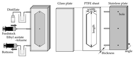
Figure 1.
The experimental setups of microdistillators.

Table 1.
Properties of the distillators.
2.3. Experimental Procedure
Using the above-described device, distillation experiments were performed using an EA–toluene mixture solution. EA–toluene solution was fed into the device at 20 °C at flow rates of 0.5, 1.0, 3.0, and 5.0 mL/min. The bottom suction rate was set to the toluene feeding rate, which was calculated by multiplying the feedstock flow rate by the feedstock toluene concentration, and each outlet solution was collected after water cooling. After 30 min from the start of heating and feedstock supply, the temperature at each measurement position in the stainless plate was confirmed to be constant; thus, it was determined to have reached a steady state. Subsequently, the distillate was collected for 10 min. The resulting distillate was weighed using an electronic balance (UX2200H, SHIMADZU, Nagoya, Japan), and the weight fraction was determined using a refractometer (RX-5000i-Plus, ATAGO, Tokyo, Japan). The composition of the bottoms was then calculated from the material balance.
3. Results
3.1. Effect of Microdistillator Angle and Observation of Flow State in Microdistillator
Firstly, the effect of the angle of the distillator was examined. The channel used was 115 mm long, 30 mm wide, and 1.3 mm thick. From the horizontal position, the angle was changed by tilting the longer side of the device. The feedstock used was 45/55 (w/w) EA–toluene, and the flow rate was set as 1.0 mL/min. The EA concentrations of the obtained solutions are shown in Figure 2. When the device was installed horizontally (angle = 0°), the feedstock was directly obtained as a distillate. However, as the angle was increased, the performance of the distillation improved, and 82.0 wt% EA was obtained as the distillate at 90°. The result was attributed to the flow state in the device. A schematic diagram of the inside of the microdevice during the experiment is depicted in Figure 3. When the experiment was conducted in a horizontal position, the gas component in the bottom section stagnated, and distillation could not be performed because the feedstock came out of the distillate section as it entered. When the device was tilted, liquid flowed from the distillate section to the bottom section along the stainless plate, and gas flowed from the bottom section to the distillate section over the flowing liquid. As a result, stable distillation was performed when the device was tilted. When the device was installed vertically, the liquid phase formed a film on the glass and stainless plates, and flowed downward by gravity. The gas phase flowed upward between the liquid films. The observation results suggested that gas-liquid contact occurred even more efficiently when the device was installed vertically on both inner walls of the flow channel at arbitrary heights. Judging from the flow state, high-efficiency distillation was expected when equilibrium between the gas and liquid was achieved quickly enough. A photo of the device during operation is provided (Supplementary Material Figure S1). According to the results, the examination was conducted with the vertically installed device from the next section.
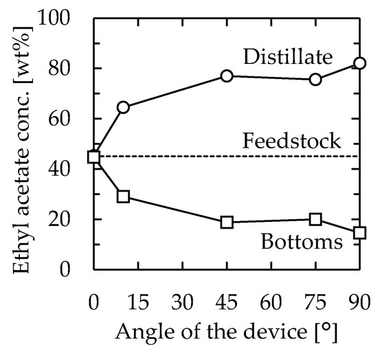
Figure 2.
Relationship between device angle and distillation performance. Channel length = 115 mm, width = 30 mm, thickness = 1.3 mm, heater temperature = 110 °C, and feedstock flow rate = 1.0 mL/min. Circle—distillate, square—bottoms.
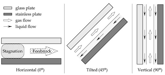
Figure 3.
Schematic diagram of the inside flow state of the microdistillator.
3.2. Effect of Feedstock Composition and Heater Temperature
The effect of the feedstock concentration was examined. The channel used was 115 mm long, 30 mm wide, and 1.3 mm thick. The device was installed vertically, as determined in the previous section. The feedstock used was 20/80, 50/50, or 80/20 (w/w) EA–toluene, and the flow rate was set as 1.0 mL/min. In this experiment, the heater temperature was set at 110 °C, 105 °C, or 90 °C for feedstock concentrations of 20/80, 50/50, or 80/20, respectively. The EA concentrations of the obtained solutions are shown in Figure 4. Regardless of the feedstock concentration, the concentration of distillate was not significantly changed, which resulted in 80–90 wt% EA. The measured temperature at the distillate section was not significantly different from the concentration, which was 83 °C, 78 °C, or 77 °C for feedstock concentrations of 20/80, 50/50, or 80/20, respectively. We speculated that the distillate and bottom concentration profiles were mainly dependent on the temperature profiles. This indicated that vapor–liquid equilibrium was reached at each position in the device for all examined feedstock concentrations and that continuous distillation based on the temperature gradient was successfully realized. Based on the following section, the feedstock concentration and the heater temperature were set as 50/50 and 110 °C, respectively.
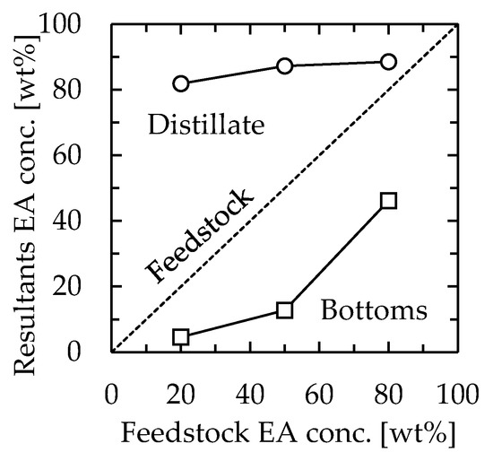
Figure 4.
Relationship between feedstock concentration and distillation performance. Channel length = 115 mm, width = 30 mm, thickness = 1.3 mm, and feedstock flow rate = 1.0 mL/min. The heater temperature was 110 °C, 105 °C, or 90 °C for feedstock concentrations of 20/80, 50/50, or 80/20, respectively. Circle—distillate, square—bottoms.
3.3. Effect of Microdistillator Channel Properties
To confirm the effect of the specific surface area of the channel on the separation performance, experiments were conducted by changing the channel thickness in the range of 0.5–7.4 mm, whereas the length and width were 115 mm and 30 mm, respectively. The temperature of the heating section was kept constant at 110 °C, and the feedstock flow rate was changed in the range of 0.5–5.0 mL/min. The relationship between the concentration of EA in the distillate and bottoms and the channel thickness is shown in Figure 5a. At feedstock flow rates below 3.0 mL/min, the separation performance decreased with increasing channel thickness. This suggested that the specific surface area has a significant effect on the performance. Considering the flow state of gas flowing between liquid films, as depicted in Figure 3, the result of separation performance improvement due to increased specific surface area was consistent. On the other hand, the separation performance tended to decrease with increasing feedstock flow rate. This was concluded to be influenced by the temperature distribution in the device.
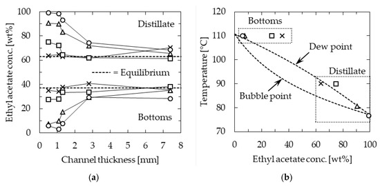
Figure 5.
Ethyl acetate (EA) concentration of microdistillation products: (a) Effect of channel thickness; (b) relationship between temperature and concentration when the channel was 0.5 mm thick. Channel length = 115 mm, width = 30 mm, and heater temperature = 110 °C. Feedstock flow rate [mL/min]; circle—0.5, triangle—1.0, square—3.0, and cross—5.0.
Figure 5b shows the temperature of the distillate and bottoms against the concentration of EA in them at a channel thickness of 0.5 mm, along with the temperature composition diagram. At a low feedstock flow rate of 0.5 mL/min, the temperature of the distillate section was 77 °C, which was close to the boiling point of EA, indicating that distillation was performed with high separation performance. In contrast, at the higher feedstock flow rate of 5.0 mL/min, the temperature profile was not well-distributed in the device, and the temperature in the distillate section was as high as 90 °C. At this temperature, the dew point composition was approximately 67 wt% EA, and therefore, the distillation resulted in a poor separation performance.
Next, experiments were conducted to change the channel volume without significantly changing the specific surface area. These attempts were conducted to increase the throughput of the device while maintaining high separation performance. All the tested channels were 1.0 mm thick, while the length was 115 or 275 mm and the width was 15 or 30 mm. The heating temperature was set as 110 or 125 °C when the length was 115 or 275 mm, respectively. The residence time was defined by Equation (1), and the flow rate was set to meet τ = 2, 3, 4, 5, 10, or 20 min.
τ [min] = (Channel volume [cm3])/(Feedstock flow rate [mL/min])
The distillation results are shown in Figure 6. We achieved similar distillation performance at higher feedstock flow rates by maintaining the specific surface area. There was no significant difference in the distillate composition with respect to the residence time, and high distillation performance was realized by ensuring a residence time of approximately 10 min. The results indicated that, by using channels of similar specific surface area, throughput was increased proportional to the channel volume.
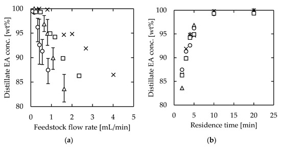
Figure 6.
EA concentration of microdistillation products (distillate) using devices with the same specific surface areas: (a) effect of feedstock flow rate; (b) effect of residence time. Channel thickness = 1.0 mm. (Channel length [mm], width [mm], and heating temperature [°C]); circle—(115, 15, 110), triangle—(115, 30, 110), square—(275, 15, 125), and cross—(275, 30, 125).
3.4. Effect of Temperature Control at the Distillate Section
According to Figure 5b, the temperature of the distillate section had a significant effect on the distillation performance. Higher performance was achieved when the distillate section temperature was approximately 77 °C, which was near the boiling point of EA. Therefore, we speculated that the distillation performance could be improved by controlling the distillate section temperature at 77 °C. The effect of temperature control on the performance of the microdistillation device was examined by changing the distillate section temperature between 60 and 80 °C. The employed device was 115 mm long, 30 mm wide, and 1.0 mm thick. The flow rate was 1.08 mL/min, which resulted in 3 min of residence time. The concentration of EA in the distillate is plotted in Figure 7 against the water temperature in the cooler during the experiment. The figure shows the concentration of EA in the distillate without the cooler as a comparison. The highest performance was obtained when the coolant temperature was 77.5 °C. When the coolant temperature was low, only gas condensation occurred in the distillate section. This dynamic suppressed the mass transfer from liquid to gas, which reduced the overall separation performance. On the other hand, when the coolant temperature was high, the distillation performance decreased. This occurred because the distillate section was heated over the boiling point of EA, and the concentration of EA decreased to the corresponding dew point according to Figure 5b. The results suggested the existence of an optimal temperature at the distillate section, which was assumed to be the boiling temperature of the low-boiling point component.
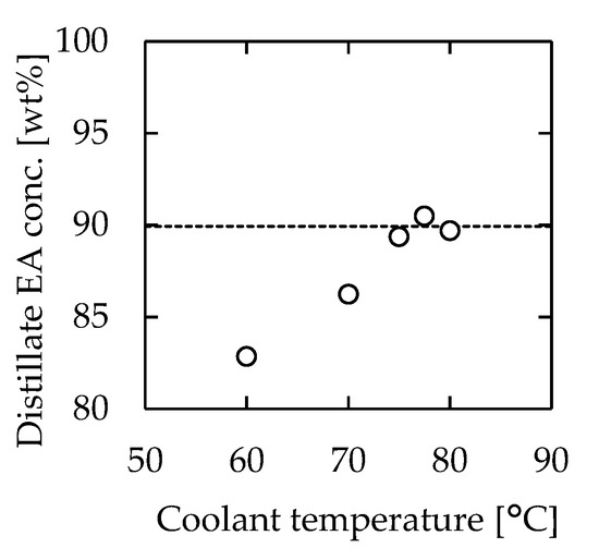
Figure 7.
Relationship between coolant temperature and EA concentration of the distillate. The dashed line indicates the result without cooling. Channel length = 115 mm, width = 30 mm, thickness = 1.0 mm, heater temperature = 110 °C, and feedstock flow rate = 1.08 mL/min.
4. Discussion
In the channel volume change experiment (results shown in Figure 6), the temperature at the distillate section was not constant even under constant conditions, resulting in errors in the product composition. However, it is essential to obtain a stable product through distillation. Because the experiment revealed that the temperature control of the distillate section was very important in determining the outcome, the stability of the product by controlling the temperature of the distillation section was further explored. Experiments were conducted using a channel that was 115 mm long, 30 mm wide, and 1.0 mm thick at a feedstock flow rate of 0.81 mL/min, with the cooler at the distillate section. The coolant temperature was set as the average temperature of the distillate section in the previous experiment without a cooler, which was 78.1 °C. The other conditions were the same as in the previous experiment. The results are shown in Figure 8, along with the results without the cooler. The number of data points for each case was 7. The importance of temperature control was clear from the results. The concentration of EA in the distillate was 95 ± 3 wt% when the temperature of the distillate section was not controlled, whereas it was 95 ± 1 wt% when the temperature was controlled, indicating that the separation accuracy was successfully improved by controlling the temperature at the distillate section.
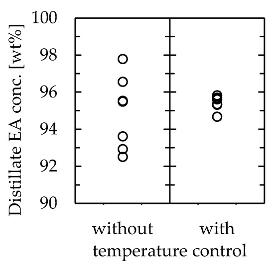
Figure 8.
Effect of distillate section temperature control on the microdistillator performance.
Next, the required number of stages in a conventional packed column distillation to achieve the same distillation performance as the microdistillation device was calculated. The conditions selected for calculation were flow rates of 0.5 and 1.0 mL/min, which were examined in Section 3.3, using a 115 mm long, 30 mm wide, and 1.1 mm thick device. Because of the structure of the apparatus used in this study, the reflux ratio could not be determined. Therefore, the reflux ratio was set as a 5-fold scalar of the minimum reflux ratio. The number of stages was calculated by the McCabe–Thiele diagram, which is shown in Figure 9. Regardless of the simple device, which consisted of stacked plates, the number of stages excluding the reboiler was 8 and 5 for feedstock flow rates of 0.5 and 1.0 mL/min, respectively.
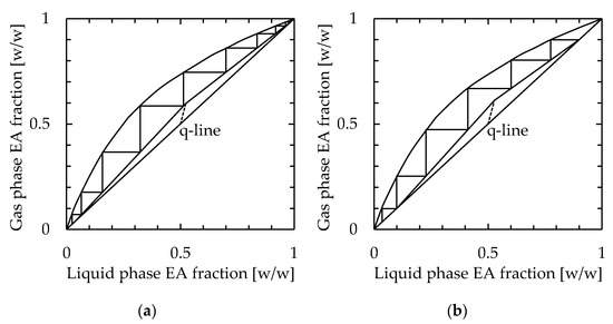
Figure 9.
Calculation of the number of stages in the packed column distillator to achieve performance by the microdistillation device. The selected conditions were feedstock flow rates of (a) 0.5 mL/min and (b) 1.0 mL/min, channel length = 115 mm, width = 30 mm, thickness = 1.1 mm, and heater temperature = 110 °C.
Subsequently, the performance of the device was evaluated using HETP as the evaluation factor. Here, HETP indicates the “height equivalent of a theoretical plate”, which is a common evaluation factor for distillation performance, and the value is expressed by Equation (2):
where a smaller value of HETP indicates a higher performance of the distillator.
HETP = (Length of the channel)/(Number of theoretical plates)
Because of the structure of the apparatus used in this study, the reflux ratio could not be determined. Therefore, the HETP was calculated using the minimum number of theoretical plates determined from the composition of the outlet fluid. The experimental devices were 30 mm wide, 1.0 mm thick, and 115 mm or 275 mm long. Figure 10 shows the corresponding results. The HETP for the devices ranged from 10–42 mm for a channel length of 115 mm to 25–69 mm for a channel length of 275 mm. Even though they exhibited a similar device performance, the large difference in HETP between the two devices occurred because the minimum theoretical stage was obtained from the outlet fluid composition, despite the lengths of the flow paths being different. In existing distillations, the HETP of a highly efficient system is approximately 100–760 mm. Thus, this system was confirmed to be up to 10 times more efficient than existing distillators.
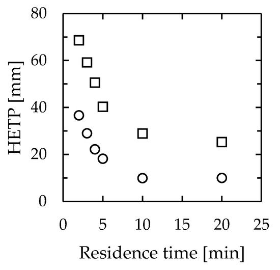
Figure 10.
Relationship between residence time and HETP in microdistillators. Channel width = 30 mm, thickness = 1.0 mm, length = circle—115 mm, and square—275 mm.
We note that the heat efficiency of the distillation device is also a very important factor. However, it was not discussed here because the manufactured device was a prototype equipped with a sheet heater on both sides. While one side was attached to the device, the other side was simply facing the air, which extremely decreased the heat efficiency. In addition, the stainless steel device was not covered with insulation, which also decreased the heat efficiency. Therefore, it was not possible to calculate the heat loss into the air, which made it difficult to discuss the heat efficiency of the device.
5. Conclusions
In this study, the separation performance and throughput of a microscale distillation device were evaluated. The effect of channel geometry was examined, and the effect of the residence time and temperature control of the distillate section were also examined. We clarified that tilting the device promoted the separation of gas and liquid phases desirably, which improved the separation performance. We also showed that increasing the slope allowed more efficient contact between the gas and liquid phases and realized a high separation performance that depended on the temperature gradient in the device. The specific surface area of the channel was clarified to have a significant effect on the separation performance of the device. This occurred because the gas-liquid contact in the device took place on the wall of the channel. We found that, for a similar specific surface area, it was possible to increase the throughput while maintaining the separation performance by increasing the channel volume. We also found that the separation performance of the device with respect to residence time was independent of the volume of the channel. Therefore, by using devices with shorter channel lengths, an approximately 10 times higher efficiency than that of conventional distillation columns, in terms of HETP, was achieved.
Supplementary Materials
The following supporting information can be downloaded at: https://www.mdpi.com/article/10.3390/separations10070404/s1, Figure S1: The picture of the device under operation. Feedstock was 50/50 (w/w) EA-toluene, channel length = 275 mm, width = 30 mm, thickness = 1.0 mm, heater temperature = 125 °C, feedstock flow rate = 1.0 mL/min, device angle = 90 °.
Author Contributions
Conceptualization, T.M. and K.M.; data curation, Y.M. and K.N.; formal analysis, Y.M. and K.N.; funding acquisition, T.M.; investigation, Y.M. and K.N.; methodology, Y.M., T.M. and K.N.; resources, Y.M. and K.N.; supervision, T.M. and K.M.; visualization, Y.M.; writing—original draft, Y.M.; writing—review and editing, Y.M. All authors have read and agreed to the published version of the manuscript.
Funding
This research was funded by JSPS KAKENHI, grant number JP16K14457.
Data Availability Statement
The data presented in this study are available in this article.
Conflicts of Interest
The authors declare no conflict of interest. The funders had no role in the design of the study; in the collection, analyses, or interpretation of data; in the writing of the manuscript; or in the decision to publish the results.
References
- McCreedy, T. Fabrication Techniques and Materials Commonly Used for the Production of Microreactors and Micro Total Analytical Systems. TrAC Trends Anal. Chem. 2000, 19, 396–401. [Google Scholar] [CrossRef]
- Mills, P.L.; Quiram, D.J.; Ryley, J.F. Microreactor Technology and Process Miniaturization for Catalytic Reactions—A Perspective on Recent Developments and Emerging Technologies. Chem. Eng. Sci. 2007, 62, 6992–7010. [Google Scholar] [CrossRef]
- Bojang, A.A.; Wu, H.-S. Design, Fundamental Principles of Fabrication and Applications of Microreactors. Processes 2020, 8, 891. [Google Scholar] [CrossRef]
- Maki, T.; Muranaka, Y.; Takeda, S.; Mae, K. Complex Polymer Nanoparticle Synthesis and Morphology Control Using an Inkjet Mixing System. Ind. Eng. Chem. Res. 2023, 62, 991–997. [Google Scholar] [CrossRef]
- Maki, T.; Takeda, S.; Muranaka, Y.; Mae, K. Silver Nanoparticle Synthesis Using an Inkjet Mixing System. Front. Chem. Eng. 2021, 3, 742322. [Google Scholar] [CrossRef]
- Watanabe, S.; Ohsaki, S.; Hanafusa, T.; Takada, K.; Tanaka, H.; Mae, K.; Miyahara, M.T. Synthesis of Zeolitic Imidazolate Framework-8 Particles of Controlled Sizes, Shapes, and Gate Adsorption Characteristics Using a Central Collision-Type Microreactor. Chem. Eng. J. 2017, 313, 724–733. [Google Scholar] [CrossRef]
- Irfan, M.; Shah, I.; Niazi, U.M.; Ali, M.; Ali, S.; Jalalah, M.S.; Khan, M.K.A.; Almawgani, A.H.M.; Rahman, S. Numerical analysis of non-aligned inputs M-type micromixers with different shaped obstacles for biomedical applications. Proc. Inst. Mech. Eng. Part E J. Process Mech. Eng. 2022, 236, 870–880. [Google Scholar] [CrossRef]
- Tamagawa, O.; Muto, A. Development of Cesium Ion Extraction Process Using a Slug Flow Microreactor. Chem. Eng. J. 2011, 167, 700–704. [Google Scholar] [CrossRef]
- Susanti, S.; Meinds, T.G.; Pinxterhuis, E.B.; Schuur, B.; de Vries, J.G.; Feringa, B.L.; Winkelman, J.G.M.; Yue, J.; Heeres, H.J. Proof of Concept for Continuous Enantioselective Liquid–Liquid Extraction in Capillary Microreactors Using 1-Octanol as a Sustainable Solvent. Green Chem. 2017, 19, 4334–4343. [Google Scholar] [CrossRef]
- Barkan-Öztürk, H.; Delorme, J.; Menner, A.; Bismarck, A. Liquid-Liquid Extraction Using Combined Hydrophilic-Hydrophobic Emulsion Templated Macroporous Polymer Micromixer-Settlers. Chem. Eng. Process.-Process Intensif. 2022, 181, 109153. [Google Scholar] [CrossRef]
- Timmer, B.H.; Van Delft, K.M.; Olthuis, W.; Bergveld, P.; Van Den Berg, A. Micro-Evaporation Electrolyte Concentrator. Sens. Actuators B Chem. 2003, 91, 342–346. [Google Scholar] [CrossRef]
- Hibara, A.; Toshin, K.; Tsukahara, T.; Mawatari, K.; Kitamori, T. Microfluidic Distillation Utilizing Micro–Nano Combined Structure. Chem. Lett. 2008, 37, 1064–1065. [Google Scholar] [CrossRef]
- Boyd, D.A.; Adleman, J.R.; Goodwin, D.G.; Psaltis, D. Chemical Separations by Bubble-Assisted Interphase Mass-Transfer. Anal. Chem. 2008, 80, 2452–2456. [Google Scholar] [CrossRef]
- Ziogas, A.; Cominos, V.; Kolb, G.; Kost, H.-J.; Werner, B.; Hessel, V. Development of a Microrectification Apparatus for Analytical and Preparative Applications. Chem. Eng. Technol. 2012, 35, 58–71. [Google Scholar] [CrossRef]
- Hartman, R.L.; Sahoo, H.R.; Yen, B.C.; Jensen, K.F. Distillation in Microchemical Systems Using Capillary Forces and Segmented Flow. Lab. Chip 2009, 9, 1843. [Google Scholar] [CrossRef]
- Wootton, R.C.R.; deMello, A.J. Continuous Laminar Evaporation: Micron-Scale Distillation. Chem. Commun. 2004, 266–267. [Google Scholar] [CrossRef]
- Sundberg, A.; Uusi-Kyyny, P.; Alopaeus, V. Novel Micro-Distillation Column for Process Development. Chem. Eng. Res. Des. 2009, 87, 705–710. [Google Scholar] [CrossRef]
- Sundberg, A.T.; Uusi-Kyyny, P.; Jakobsson, K.; Alopaeus, V. Control of Reflux and Reboil Flow Rates for Milli and Micro Distillation. Chem. Eng. Res. Des. 2013, 91, 753–760. [Google Scholar] [CrossRef]
- Seok, D.R.; Hwang, S.-T. Zero-Gravity Distillation Utilizing the Heat Pipe Principle(Micro-Distillation). AIChE J. 1985, 31, 2059–2065. [Google Scholar] [CrossRef]
- Lam, K.F.; Cao, E.; Sorensen, E.; Gavriilidis, A. Development of Multistage Distillation in a Microfluidic Chip. Lab. Chip 2011, 11, 1311. [Google Scholar] [CrossRef]
- Lam, K.F.; Sorensen, E.; Gavriilidis, A. Towards an Understanding of the Effects of Operating Conditions on Separation by Microfluidic Distillation. Chem. Eng. Sci. 2011, 66, 2098–2106. [Google Scholar] [CrossRef]
- Zhang, Y.; Kato, S.; Anazawa, T. Vacuum Membrane Distillation by Microchip with Temperature Gradient. Lab. Chip 2010, 10, 899. [Google Scholar] [CrossRef] [PubMed]
- MacInnes, J.M.; Ortiz-Osorio, J.; Jordan, P.J.; Priestman, G.H.; Allen, R.W.K. Experimental Demonstration of Rotating Spiral Microchannel Distillation. Chem. Eng. J. 2010, 159, 159–169. [Google Scholar] [CrossRef]


Disclaimer/Publisher’s Note: The statements, opinions and data contained in all publications are solely those of the individual author(s) and contributor(s) and not of MDPI and/or the editor(s). MDPI and/or the editor(s) disclaim responsibility for any injury to people or property resulting from any ideas, methods, instructions or products referred to in the content. |
© 2023 by the authors. Licensee MDPI, Basel, Switzerland. This article is an open access article distributed under the terms and conditions of the Creative Commons Attribution (CC BY) license (https://creativecommons.org/licenses/by/4.0/).