Article

Conjugated Mass Transfer of CO2 Absorption through Concentric Circular Gas–Liquid Membrane Contactors

1
Department of Chemical and Materials Engineering, Tamkang University, Tamsui, New Taipei 251, Taiwan
2
Department of Fundamental and Applied Sciences, HICoE-Centre for Biofuel and Biochemical Research, Institute of Self-Sustainable Building, Universiti Teknologi PETRONAS, Seri Iskandar 32610, Malaysia
*
Author to whom correspondence should be addressed.
Processes 2021, 9(9), 1580; https://doi.org/10.3390/pr9091580
Submission received: 4 August 2021 / Revised: 27 August 2021 / Accepted: 1 September 2021 / Published: 3 September 2021

Abstract

:
A new design of gas absorption that winds the permeable membrane onto an inner concentric tube to conduct a concentric circular gas–liquid membrane module has been studied theoretically in the fully developed region. An analytical formulation, referred to as conjugated Graetz problems, is developed to predict the concentration distribution and Sherwood numbers for the absorbent fluid flowing in the shell side and CO2/N2 gas mixture flowing in the tube side under various designs and operating parameters. The analytical solutions to the CO2 absorption efficiency were developed by using a two-dimensional mathematical modeling, and the resultant conjugated partial differential equations were solved analytically using the method of separation variables and eigen-function expansion in terms of power series. The predictions of CO2 absorption rate by using Monoethanolamide (MEA) solution in concentric circular membrane contactors under both concurrent- and countercurrent-flow operations are developed theoretically and confirmed with the experimental results. Consistency in both a good qualitative and quantitative sense is achieved between the theoretical predictions and experimental results. The advantage of the present mathematical treatment provides a concise expression for the chemical absorption of CO2 by MEA solution to calculate the absorption rate, absorption efficiency, and average Sherwood number. The concentration profiles with the mass-transfer Graetz number, inlet CO2 concentration, and both gas feed and absorbent flow rates are also emphasized. Both theoretical predictions and experimental results show that the device performance of the countercurrent-flow operation is better than that of the concurrent-flow device operation. The availability of such simplified expressions of the absorption rate and averaged Sherwood as developed directly from the analytical solutions is the value of the present study.

1. Introduction

Membrane contactor modules were applied to gas/liquid absorption process in aiming to avoid the existence of foaming, unloading and flooding in packed towers, bubble columns, and spray towers, which is performed in conventional gas absorption processes to remove CO2 by absorbing with the gas mixtures dispersed into an aqueous amines solution. Using aqueous amines allows the simple heating process to regenerate the liquid absorbents. A substitutive gas absorption process has gained increasing attention in recent years as an alternative technology for capturing CO2 [1]. Implementing hydrophobic microporous membranes [2,3] to overcome the disadvantage of non-dispersive contact allows the soluble gas to be absorbed on the membrane surface in the pore mouth adjacent to the solvent phase. The benefits of both membrane reactor and gas/liquid absorption processes were combined together in chemical absorption processes, which are widely utilized due to the high selectivity of amines towards CO2 absorption. Karoor and Sirkar [3] used the hollow fiber membrane contactor to separate CO2/N2 by using pure water as absorbents (physical absorption processes) or amine aqueous solutions (chemical absorption processes). The absorption efficiency of such membrane contactors is dependent on the distribution coefficient of gas solute between gas and absorbent phases. Numerous absorbent solutions [4,5] or hollow-fiber modules [6,7] used for CO2 absorption improvement were further studied by many investigators. Polytetrofluoroethylene (PTFE) denotes the superior membrane material for absorption processes due to its extreme hydrophobicity [8] for the common amine solvents. Membrane gas absorption offers many advantages including the independent control of gas and absorbent flow rates, high contact surface area, and linear scale-up compared to traditional equipment [9].
The film theory has been described in a gas/liquid membrane contactor as a mass-transfer resistances in series model [10], in which the liquid can be contacted on the opposite side of the membrane and the gas/liquid interface is formed at each membrane pore entrance. The mass-transfer resistance in the absorbent solution was a dominant resistance when CO2 diffused across the membrane and absorbed into the absorbent solution. Many mathematical models were developed [11,12] in order to study and evaluate the influences of absorption efficiency of CO2 [13]. Two conjugated governing equations for solving CO2 concentration distributions and the outlet concentrations were obtained by using the orthogonal technique and the method of separation of variables [14,15]. Theoretical investigation of two-dimensional concentration distributions in the gas/liquid concentric circular membrane extractor modules is the value of the present study. The purposes of this study are to develop the two-dimensional mathematical formulation of concentric circular gas/liquid membrane extractors, to solve the resultant partial differential equations analytically by using orthogonal expansion method, and to find the dimensionless outlet average concentrations for both gas and liquid streams. The operating conditions that affect device performance including gas and liquid flow rates and inlet CO2 concentrations were investigated to examine the absorption rate in the concentric circular membrane contactor. The theoretical predictions of average Sherwood number are presented graphically with the mass-transfer Graetz number as the parameter. The theoretical results of absorption efficiency and absorption rate for concurrent- and countercurrent-flow patterns are compared to the experimental data to confirm the two-dimensional theoretical model in practical manners.

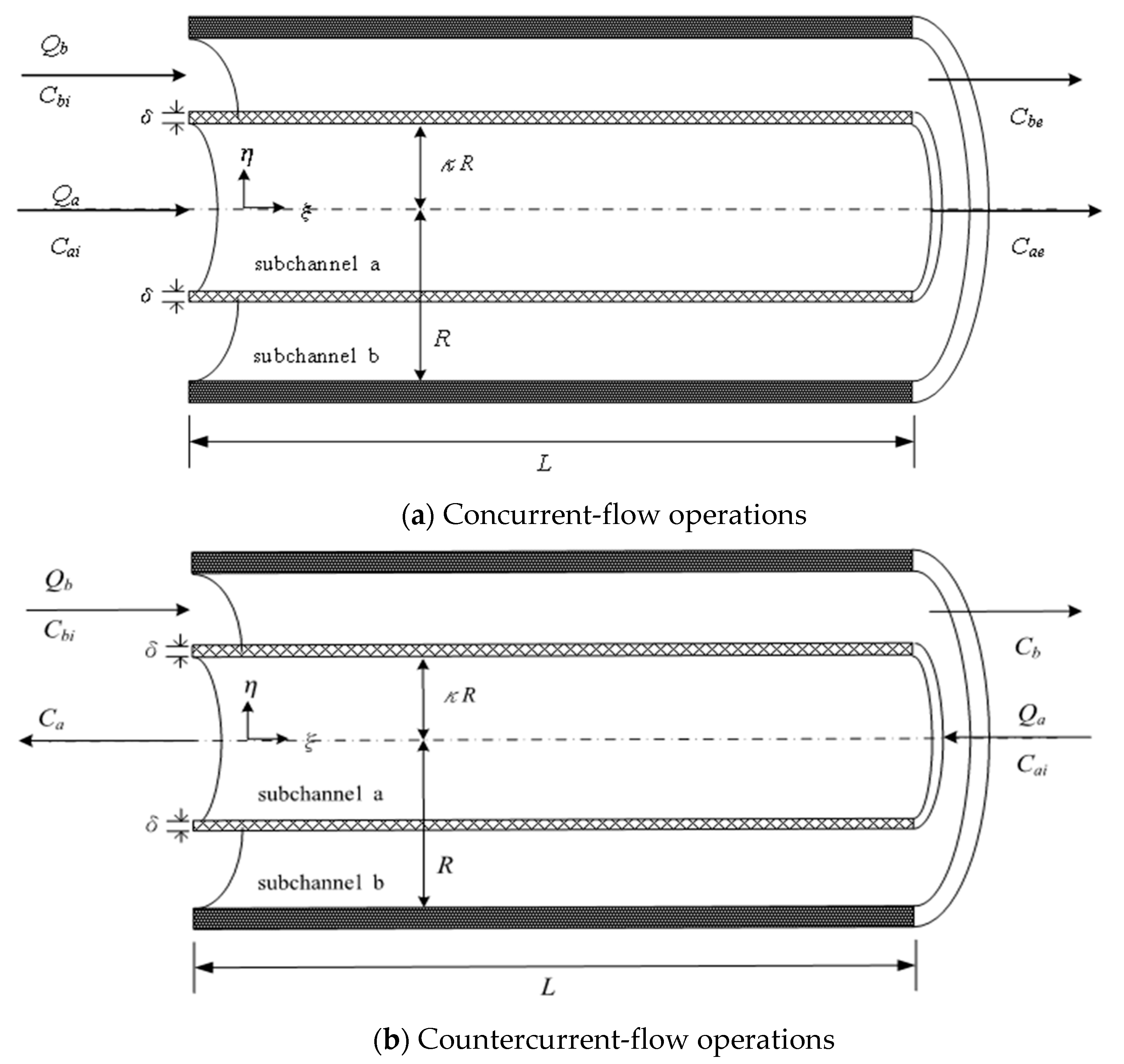
2. Mathematical Formulations

Figure 1 shows a concentric circular gas/liquid membrane contactor that has a hydrophobic microporous permeable membrane which is wound in order to divide a circular tube into an inner tube and shell side with thicknesses of 2 κ R and 2 ( 1 κ ) R , respectively. The hydrophobic microporous membrane with negligible thickness δ between gas feed and absorbent flow is passed through each channel individually. The volumetric flow rates Q a and Q b , and the inlet concentration C a i and C b i , are key for gas and liquid streams, respectively. The overall mass transfer resistance includes gas film resistance of transferring through the bulk gas phase, liquid film resistance of gas transferring into the bulk liquid phase, and the resistance diffusion through the membrane pores.

2.1. Concurrent-Flow Operations

The mathematical formulations of the velocity profiles and mass conservation equations in describing the mass transfer behavior, as shown in Figure 1a, are derived after the following assumptions are made: (a) steady state and isothermal condition; (b) fully developed flow in both inner tube and shell side; (c) the physical properties of gas and liquid are constant; (d) negligible axial diffusion and conduction, entrance length, and end effects; (e) the applicability of Henry’s law; (f) the applicability of thermodynamic equilibrium; (g) reaching the equilibrium state immediately with the assumed fast chemical reaction rate; (h) neglecting the membrane thickness compared to the circular-tube radius.
[ v a R 2 L D a ] ψ a ( η , ξ ) ξ = 1 η [ η ( η ψ a ( η , ξ ) η ) ]
[ v b R 2 L D b ] ψ b ( η , ξ ) ξ = 1 η [ η ( η ψ b ( η , ξ ) η ) ] k C O 2 ψ b ( η , ξ )
v a ( η ) = 2 v a ¯ [ 1 ( η κ ) 2 ] ,   0 η κ
v b ( η ) = 2 v b ¯ [ 1 κ 4 1 κ 2 1 κ 2 ln ( 1 / κ ) ] [ 1 η 2 + ln ( 1 κ 2 ln ( 1 / κ ) ) ln η ] ,     κ η 1
in which
η = r R ,   ξ = z L ,   ψ a = C a C a i ,   ψ b = C b C a i ,   G z a = v a ¯ R 2 L D a ,   G z b = v b ¯ R 2 L D b
The boundary conditions accompanied with the conjugated governing Equations (3) and (4) are
ψ a ( η , 0 ) = ψ a i
ψ b ( η , 0 ) = ψ b i
ψ a ( 0 , ξ ) η = 0
ψ b ( 1 , ξ ) η = 0
ψ a ( κ , ξ ) η = ε R δ [ ψ a ( κ , ξ ) K e x H ψ b ( κ , ξ ) ]
D a ψ a ( κ , ξ ) η = D b K e x H ψ b ( κ , ξ ) η
in which the reduced equilibrium constant K e x = K e x [ MEA ] / [ H   + ] and the equilibrium constant K e x = [ MEACOO - ] [ H + ] / { [ CO 2 ] [ MEA ] } = 1.25 × 10 5 at T = 298 K [16] of the CO2 absorption from gas phase to MEA aqueous solution, and the dimensionless Henry’s law constant H = 0.73 [17].
The present work is actually the extension of our previous work [18] by following the similar general solution form except instead of concentric circular module, but the mathematical treatment is more complicated than that in the flat-plate module. The dimensionless concentration profiles of both phases, ψ a and ψ b , in such a conjugated system were obtained analytically with the use of an orthogonal expansion technique by the eigen-function expanding in terms of an extended power series [19,20], the separation variables are expressed in the form:
ψ a ( η , ξ ) = m = 0 S a , m F a , m ( η ) G m ( ξ )
ψ b ( η , ξ ) = m = 0 S b , m F b , m ( η ) G m ( ξ )
We may assume the eigen-functions F a , m ( η a ) and F b , m ( η b ) to be expressed in polynomials without loss of generality in the following forms:
F a , m ( η ) = n = 0 d m n η n , d m , 0 = 1   ( selected ) ,   d m , 1 = 0
F b , m ( η ) = n = 0 e m n η n , e m , 0 = 1   ( selected ) ,   e m , 1 = 0
Substitutions of Equations (12) and (13) into Equations (3) and (4) and the boundary conditions in Equations (8)–(11) leads to
G m ( ξ ) = e λ m ξ
F a , m ( η ) + 1 η F a , m ( η ) + [ λ m R 2 v a ( η ) L D a ] F a , m ( η ) = 0
F b , m ( η ) + 1 η F b , m ( η ) + [ λ m R 2 v b ( η ) L D b ] F b , m ( η ) k C O 2 F b , m ( η ) = 0
F a , m ( 0 ) = 0
F b , m ( 1 ) = 0
S a , m F a , m ( κ ) = ( ε   R δ ) [ S a , m F a , m ( κ ) K e x H S b , m F b , m ( κ ) ]
S a , m F a , m ( κ ) = ( D b D a ) K e x H S b , m F b , m ( κ )
Equation (21) was rewritten to obtain the relationship between S a , m and S b , m as
S b , m = H [ δ F a , m ( κ ) + ε R F a , m ( κ ) ] ε R K e x F b , m ( κ ) S a , m
Moreover, combinations of Equations (21) and (22) with deleting S a , m and S b , m yields the following equations to calculate the eigenvalues ( λ 1 , λ 2 , …, λ m , …)
F a , m ( κ ) = ε   R δ [ F a , m ( κ ) + ( D a D b ) F a , m ( κ ) F b , m ( κ ) F b , m ( κ ) ]
All the coefficients d m , n and e m , n may be expressed in terms of eigenvalues λ m after using Equations (19) and (20) by substituting Equations (14) and (15) into Equations (17) and (18), and can be expressed in terms of eigenvalue λ m as
d m 2 = G z a λ m 2 , d m , n = 2 λ m G z a [ n ( n 1 ) + n ] ( d m ( n 2 ) 1 κ 2 d m ( n 4 ) ) , n = 4 , 5 , 6 ,
and
e m , 2 = 1 2 λ m G z b S [ 1 3 T 2 ] + k C O 2 4 ,   e m 3 = 4 9 λ m G z b T S , e m , n = λ m G z   b S [ n ( n 1 ) + n ] [ ( 1 3 2 T ) e m , ( n 2 ) + 2 T e m , ( n 3 ) ( 1 + 1 2 T ) e m , ( n 4 ) ] n = 4 , 5 , 6 ,
where T = 1 κ 2 ln   ( 1 / κ ) and S = 1 κ 4 1 κ 2 1 κ 2 ln   ( 1 / κ ) .
These eigenvalues λ m were calculated in Equation (24), requiring a negative set for both concurrent and countercurrent-flow operations. Table 1 shows that calculation results of the first five eigenvalues and their associated expansion coefficients are selected to meet the convergence requirement, and the dimensionless outlet concentration profiles of the gas feed with the terms n = 500 employed during the calculation procedure are acceptable due to the negligible truncation error of Q a = 5.0 × 10 6   m 3 / s and Q b = 6.67 × 10 6   m 3 / s under both concurrent- and countercurrent-flow operations as an illustration.
The orthogonality condition used in the concentric circular membrane contactor system of the case λ m λ n is verified, to solve for coefficients S a , m and S b , m as follows:
D a   0   κ η [ R 2 v a ( η ) L D a ] S a , m S a , n F a , n ( η ) F a , m ( η ) d η + D b K e x H   κ   1 η [ R 2 v b ( η ) L D b ] S b , m S b , n F b , n ( η ) F b , m ( η ) d η = 0
The dimensionless inlet and outlet concentrations can be obtained in the form of an infinite series by incorporating ξ = 0 and ξ = 1 into Equations (12) and (13) as
ψ a ( η , 0 ) = m = 0 S a , m F a , m ( η )
ψ b ( η , 0 ) = m = 0 S b , m F b , m ( η )
ψ a ( η , 1 ) = m = 0 S a , m F a , m ( η ) e λ m
ψ b ( η , 1 ) = m = 0 S b , m F b , m ( η ) e λ m
By following the similar derivation performed in the previous study [14], the expansion coefficient of S a , n and S b , n with the aid of Equation (23) are thus obtained using boundary conditions of Equations (28)–(31) as follows:
( i )   n = 0 G z a κ 2 ψ a i 2 + G z b ( 1 κ 2 ) D b ψ b i 2 D a = q = 0 S a , q e λ q { 0 κ η [ v a R 2 L D a ] F a , q d η + D b D a K e x H κ 1 η [ v b R 2 L D b ] ( H [ δ F a , q ( κ ) + ε R F a , q ( κ ) ] ε R K e x F b , q ( κ ) ) F b , q d η } = S a , 0 ( G z a κ 2 2 + G z b ( 1 κ 2 ) D b 2 D a ) q = 1 S a , q κ   e λ q λ q { F a , q ( κ ) D b [ δ F a , q ( κ ) + ε R F a , q ( κ ) ] D a ε R F b , q ( κ ) F b , q ( κ ) }
( ii )   n 0   , n = q ψ a i λ n κ F a , n ( κ ) + D b D a K e x H ψ b i κ H [ δ F a , n ( κ ) + ε R F a , n ( κ ) ] F b , n ( κ ) ε R K e x λ n F b , n ( κ ) = q = 1 S a , q κ { [ F a , n λ n ( κ ) F a , n ( κ ) F a , n λ n ( κ ) F a , n ( κ ) ] + D b D a K e x H [ H [ δ F a , n ( κ ) + ε R F a , n ( κ ) ] ε R K e x F b , n ( κ ) ] 2 [ F b , n λ n ( κ ) F b , n ( κ ) F b , n λ n ( κ ) F b , n ( κ ) ] }
( iii )   n 0   , n q ψ a i λ n κ F a , n ( κ ) + D b D a K e x H ψ b i κ H [ δ F a , n ( κ ) + ε R F a , n ( κ ) ] F b , n ( κ ) ε R K e x λ n F b , n ( κ ) = S a , 0 κ e λ n λ n { F a , n ( η i ) + D b D a K e x H [ [ δ F a , n ( κ ) + ε R F a , n ( κ ) ] ε R K e x ] F b , n ( κ ) F b , n ( κ ) } + q = 1 S a , q κ e λ n λ q λ q λ n { [ F a , n ( κ ) F a , q ( κ ) F a , n ( κ ) F a , q ( κ ) ] + H D b D a [ δ F a , n ( κ ) + ε R F a , n ( κ ) ] [ δ F a , q ( κ ) + ε R F a , q ( κ ) ] ε 2 R 2 K e x }
Thus, the dimensionless averaged concentrations in axial direction were obtained from Equations (12) and (13) with the aid of Equation (23) integrating in gas and absorbent streams, respectively
ψ a ¯ ( ξ ) = 0 κ v a 2 π R 2 η ψ a ( η , ξ ) d η 0 κ v a 2 π R 2 η d η = S a , 0 2 G z a κ m = 1 1 λ m S a , m F a , m ( κ ) e λ m ξ
ψ b ¯ ( ξ ) = κ 1 v b 2 π R 2 η ψ b ( η , ξ ) d η κ 1 v b 2 π R 2 η d η = S b , 0 2 κ G z b ( 1 κ 2 ) m = 1 1 λ m S b , m F b , m ( κ ) e λ m ξ

2.2. Countercurrent-Flow Operations

The modeling equations of mass transfer for both gas and absorbent streams may also be obtained in the similar forms as referred to Equations (1) and (2), as shown in Figure 1b, except replacing the velocity distribution of Equation (3) and boundary condition of Equation (11) by Equations (37) and (38), respectively
v a ( η ) = 2 v a ¯ [ 1 ( η κ ) 2 ] ,   0 η κ
ψ a ( η , 1 ) = ψ a i   at   ξ = 1
The results of all coefficients may be obtained as follow:
( i )   n = 0 G z a κ 2 ψ a i 2 G z b ( 1 κ 2 ) D b ψ b i 2 D a = S a , 0 ( G z a κ 2 2 G z b ( 1 κ 2 ) D b 2 D a ) q = 1 S a , q κ λ q { F a , q ( κ ) D b e λ q [ δ F a , q ( κ ) + ε R F a , q ( κ ) ] D a ε R F b , q ( κ ) F b , q ( κ ) }
( ii )   n 0   , n = q ψ a i λ n κ F a , n ( κ ) D b D a K e x H ψ b i κ H [ δ F a , n ( κ ) + ε R F a , n ( κ ) ] F b , n ( κ ) ε R K e x λ n F b , n ( κ ) = q = 1 S a , q κ { [ F a , n λ n ( κ ) F a , n ( κ ) F a , n λ n ( κ ) F a , n ( κ ) ] D b D a K e x H [ H [ δ F a , n ( κ ) + ε r f F a , n ( κ ) ] K e x ε R F b , n ( κ ) ] 2 [ F b , n λ n ( κ ) F b , n ( κ ) F b , n λ n ( κ ) F b , n ( κ ) ] }
( iii )   n 0   , n q ψ a i λ n κ F a , n ( κ ) + D b D a K e x H ψ b i κ H [ δ F a , n ( κ ) + ε R F a , n ( κ ) ] F b , n ( κ ) K e x λ n ε R F b , n ( κ ) = S a , 0 κ e λ n λ n { F a , n ( η i ) D b D a K e x H [ [ δ F a , n ( κ ) + ε R F a , n ( κ ) ] ε R K e x ] F b , n ( κ ) F b , n ( κ ) } + q = 1 S a , q κ e λ n λ q λ q λ n { [ F a , n ( κ ) F a , q ( κ ) F a , n ( κ ) F a , q ( κ ) ] D b D a H [ δ F a , n ( κ ) + ε R F a , n ( κ ) ] [ δ F a , q ( κ ) + ε R F a , q ( κ ) ] ε 2 R 2 K e x }
Similarly, the dimensionless radially averaged concentrations of both absorbent and gas streams are
ψ a ¯ ( ξ ) = S a , 0 + 2 G z a κ m = 1 1 λ m S a , m F a , m ( κ ) e λ m ξ
ψ b ¯ ( ξ ) = S b , 0 2 κ G z b ( 1 κ 2 ) m = 1 1 λ m S b , m F b , m ( κ ) e λ m ξ

2.3. Absorption Efficiency

The CO2 absorption rate was calculated as follows:
ω = Q a ( C a i ¯ C a e ¯ )
The absorption efficiency I M was illustrated by calculating the percentage of CO2 absorbed in the concentric circular membrane contactor module as
I M = C a i ¯ C a e ¯ C a i ¯ × 100 %
Furthermore, the local mass-transfer coefficient in the absorbent solution plays an important role to dominate absorption efficiency and could be obtained by
k b ξ = D b R ψ b ( κ , ξ ) / η ψ b ( κ , ξ ) K e x H ψ ¯ b ( ξ )
The local Sherwood number is defined by
S h ξ = k b ξ D e q , b D b
where D   b and D e q , b are the diffusivity of CO2 and the equivalent diameter in the liquid stream, and the averaged Sherwood number is thus obtained by integrating the local Sherwood number within the conduit length
S h ¯ = 0 1 S h ξ d ξ = 0 1 2 ( 1 κ ) m = 1 S b , m F b , m ( κ ) e λ m ξ m = 1 S b , m [ F b , m ( κ ) K e x H 2 κ G z b ( 1 κ 2 ) λ m F b , m ( κ ) ] e λ m ξ d ξ

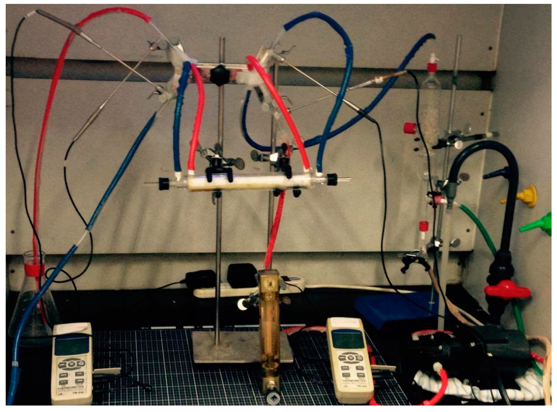
3. Experimental Apparatus

The experimental setup of the membrane absorption of CO2 by using MEA absorbent flowing into the concentric circular gas–liquid membrane contactor is illustrated by Figure 2. A hydrophobic polytetrafluoroethylene (PTFE) composite membrane of a nominal pore size of 0.2   μ m , a porosity of 0.72 and a thickness of 130   μ m with supported polypropylene (PP) net is used in the experiments for its superior chemical resistance and thermal stability. The hydrophobic PTFE/PP composite membrane (manufactured by ADVANTEC, Japan, J020A330R) is inserted for most chemically aggressive solvents, strong acids and bases, and thermostable up to 100 °C with an operating temperature range of −35 °C~130 °C. Figure 2 illustrates the schematic configurations of the concentric circular gas/liquid membrane contactor module, in which the MEA solution passes through the shell side and the gas feed flows into the tube side. A photo of the operating circular-tube experimental apparatus is shown in Figure 3. The photo of a more detailed configuration of the concentric-tube membrane contactor module is represented by Figure 4.
The inner concentric ring tube was made of stainless-steel wire matrix (No. 3016) with 1.5 cm inside diameter shown in Figure 4a, which was formed with perforated holes of 1.26 mm × 1.26 mm square to allow gas to diffuse through. A hydrophobic membrane PTFE/PP was wound around the circumference of the surface of the circular wire matrix ring tube, and routed with a 0.2 mm nylon fiber on the membrane surface on the outside of the inner tube shown in Figure 4c. The empty lumen channel in concentric circular membrane contactor tube is constructed by using an effective 0.2 m long concentric tubular acrylic tube of outer diameter 3.0 cm shown in Figure 4d. A gas mixture containing CO2/N2 from the gas mixing tank, and the MEA solution from a reservoir in thermostat (G-50, 60L, 3500W, DENG YNG, New Taipei, Taiwan) were selected as the feed gas and the absorbent solution, respectively. The various operation conditions of flow rate for liquid absorption with various flow rates (5.0, 6.67, 8.33, and 10.0 cm3/s) into the lumen channel were regulated by a flow meter (MB15GH-4-1, Fong-Jei, New Taipei, Taiwan), while keeping a gas stream containing CO2/N2 from the gas mixing tank (EW-06065-02, Cole Parmer company, Chicago, IL, USA) with a fixed flow rate of 5.0 cm3/s into the inner tube by using the mass flow controller (S/N:12031501PC-540, Brooks Instrument, Protec, Hatfield, PA, USA). The 30 wt% MEA solution was prepared to conduct experimental runs for various inlet CO2 concentrations (30, 35 and 40%). The outlet CO2 concentrations flowing out from the inner tube were then monitored and measured with gas chromatography (Model HY 3000 Chromatograp, China Corporation). The specifications and parameters of the experimental runs are summarized in Table 2.
The experimental results deviate from the theoretical predictions calculating by the following definition of the accuracy deviation [21]
E   ( % ) = 1 N exp i = 1 N exp | ω t h e o , i ω exp , i | ω exp , i × 100
where Nexp, ω t h e o , i and ω exp , i are the number of experimental runs, theoretical predictions and experimental results of absorption rates, respectively. The accuracy deviations of both concurrent- and countercurrent-flow operations are shown in Table 3. The accuracy deviation of experimental results from theoretical predictions is within expectation and goes reasonably well, at 6.63 × 10 2 E 7.74 × 10 2 .

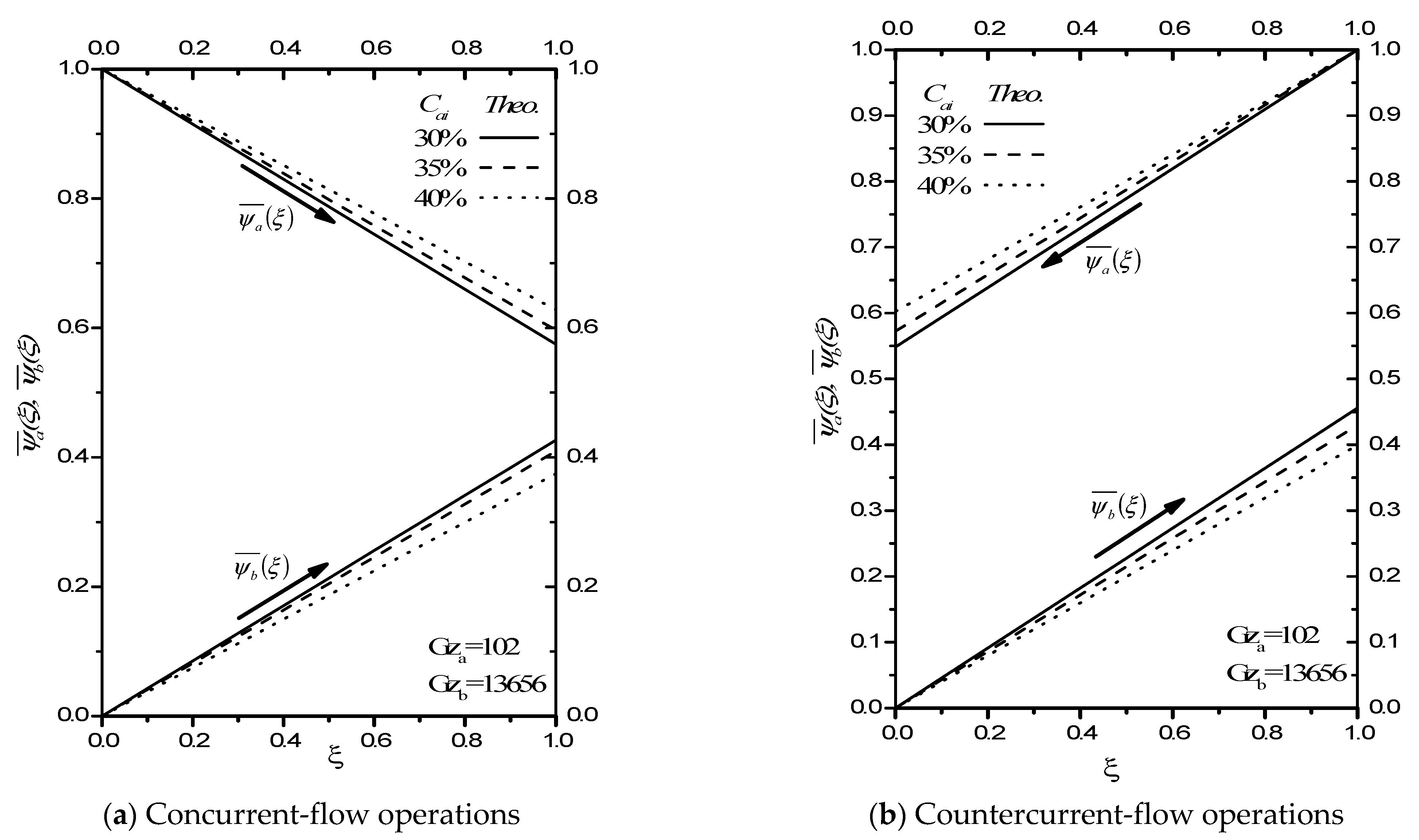
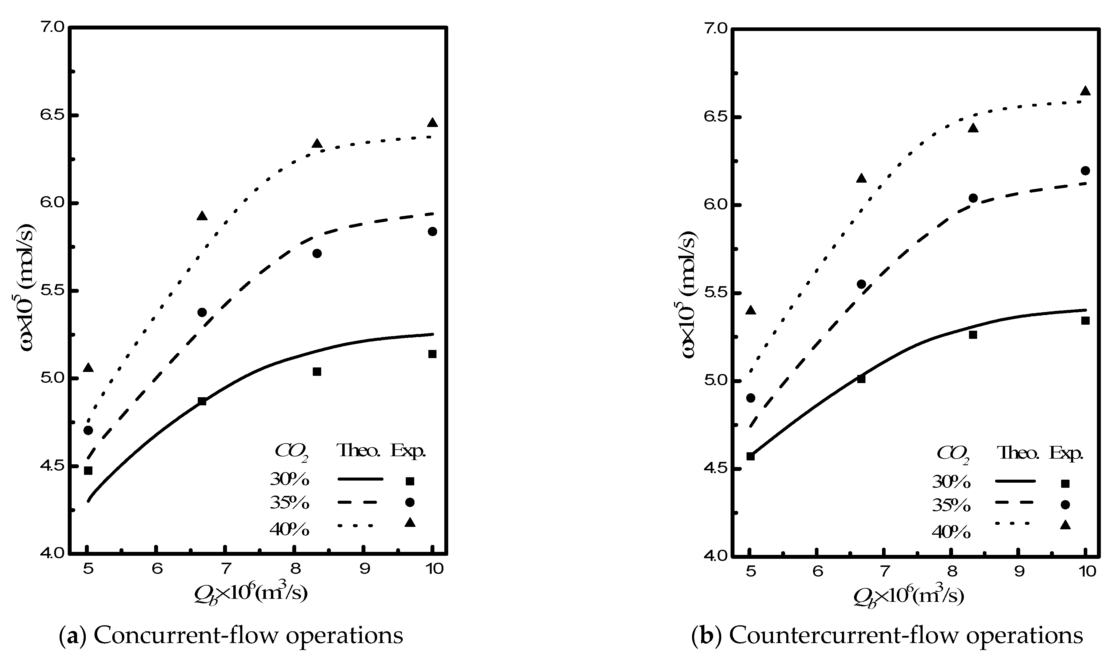
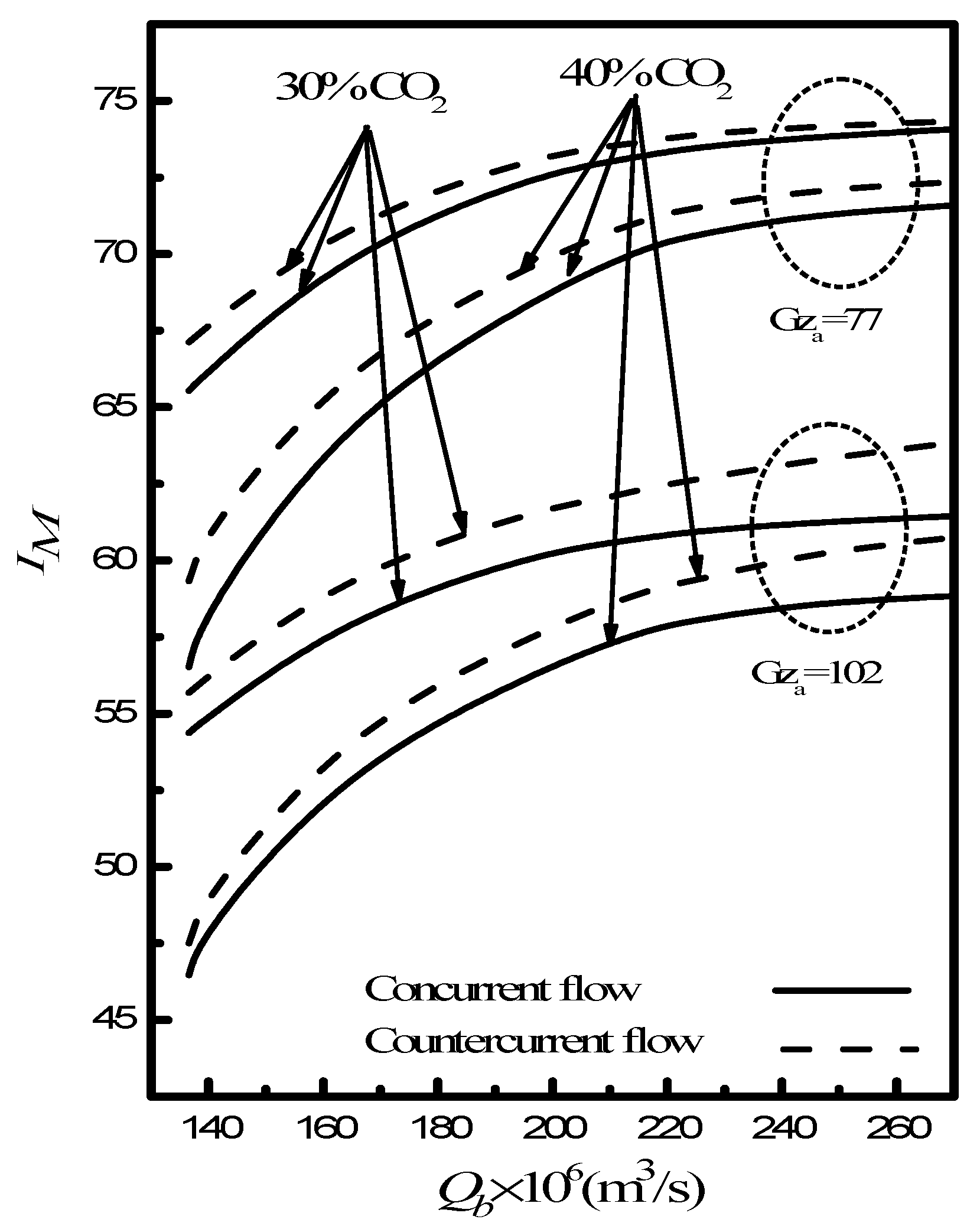
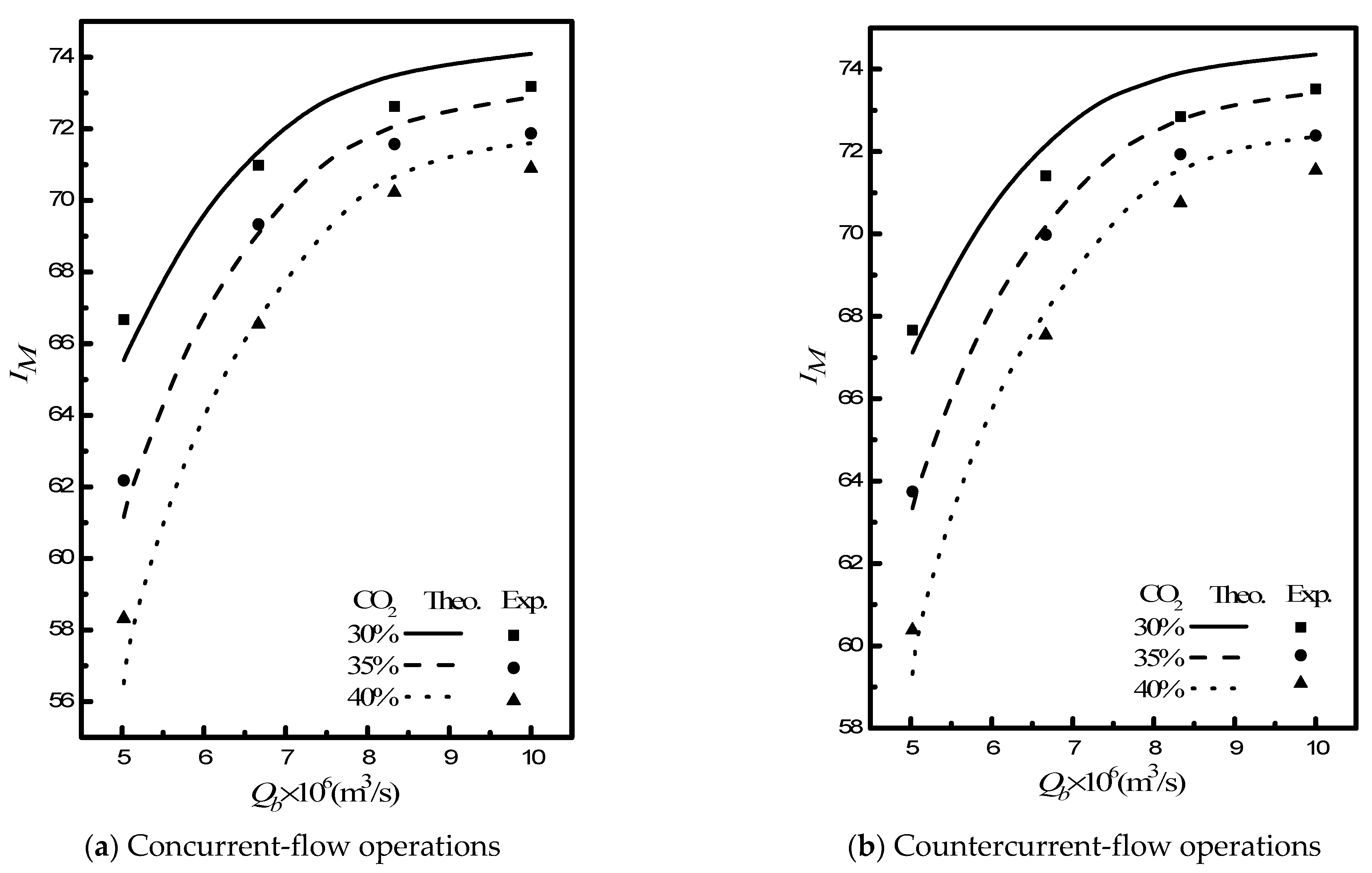
4. Results and Discussion

The procedure for calculating the theoretical values of the dimensionless outlet average concentration, absorption rate and absorption efficiency are described as follows. First, the eigenvalues in the membrane contactor are solved from Equation (24), the associated eigen-functions obtained from Equations (25) and (26). Next, the expansion coefficients S a , n are calculated from Equations (32)–(34) for the concurrent-flow operations and from Equations (39)–(41) for countercurrent-flow operations. Thus, the expansion coefficients S b , n are obtained from Equation (23). Last, the dimensionless averaged outlet concentrations are calculated from Equations (35) and (36) for concurrent-flow operations and from Equations (42) and (43) for countercurrent-flow operations. The absorption rate, absorption efficiency, mass transfer coefficient, and averaged Sherwood number are calculated from Equations (44), (45) and (48), respectively.
Figure 5a,b shows the dimensionless averaged CO2 concentration profiles along the axial direction in both gas and liquid phases for various inlet CO2 concentrations under both concurrent- and countercurrent-flow operations. Notice that the axial dimensionless averaged concentration distribution in the absorbent solution, ψ b ¯ ( ξ ) , increases as the inlet CO2 concentration decreases from 45% to 30%. The results show that a higher driving-force concentration gradient is kept between two phases under a larger inlet CO2 concentration, which turns out to have a higher absorption rate, leading to a smaller dimensionless averaged outlet CO2 concentration for both flow patterns.
Comparisons were made of both theoretical predictions and experimental results of dimensionless outlet CO2 concentrations for both concurrent- and countercurrent-flow operations, demonstrated in Figure 6. It can be observed from Figure 6 that the dimensionless outlet CO2 concentration increases with the magnitude of inlet CO2 concentration. The theoretical predictions of dimensionless outlet CO2 concentrations are consistent with experimental results. The comparison reveals that the higher the absorbent flow rate, the lower the dimensionless outlet CO2 concentration found in both flow patterns, which is also as expected.
The local mass-transfer Graetz number symbolizes the ratio of mass transfer coefficient in radial direction versus diffusion in axial direction, say S h ξ = k b ξ D e q , b / D b . The averaged mass-transfer Sherwood number S h ¯ plays a significant role in determining the CO2 absorption rate in considering the mass transfer behavior. The theoretical prediction S h ¯ which varies with the mass-transfer Graetz number of the absorbent solution (absorbent flow rates Q b ) for both concurrent- and countercurrent-flow operations is presented in Figure 7, where the averaged mass-transfer Sherwood number S h ¯ in countercurrent-flow operations is higher than that in concurrent-flow operations. This result confirms that the higher mass transfer coefficient is obtained in countercurrent-flow operations that come up with a higher absorption rate due to lower outlet CO2 concentrations, as demonstrated in Figure 6. It’s reasonable to conclude that the mass transfer rate represented by S h ¯ increases in a linear relationship the smaller the mass-transfer Graetz number of the absorbent solution.
Theoretical predictions and experimental results of CO2 absorption rate that vary with absorbent flow rate and inlet CO2 concentration in both concurrent- and countercurrent-flow operations, as indicated in Figure 8 for comparison. The results show that the CO2 absorption rate increases with the absorbent flow rates. Meanwhile, the CO2 absorption rate is higher in countercurrent-flow operations than that in concurrent-flow operations, as shown in Figure 8. The higher absorbent flow rate and inlet CO2 concentration obtain a higher CO2 absorption rate as predicted above accordingly.
Figure 9 illustrates the deviation between the theoretical predictions and experimental results of CO2 absorption efficiency that vary with absorbent flow rate and inlet CO2 concentrations for both flow patterns. Notice that the higher inlet CO2 concentration results in the higher CO2 absorption rate but the lower absorption efficiency, as shown in Figure 8 and Figure 9, respectively. In addition, the CO2 absorption efficiency is found to be increased with increasing absorbent flow rate. One may find the experimental result is most consistent with the theoretical prediction at the lower absorbent flow rate. The discrepancy between theoretical predictions and experimental result is increasing as the absorbent flow rate increases.
The effect of the operating parameters investigated on the absorption efficiency includes gas and absorbent flow rates, inlet CO2 concentration, and flow patterns. Figure 10 illustrates the CO2 absorption efficiency I M varies with mass-transfer Graetz number G z b with inlet CO2 concentrations and gas feed rates as parameters under both concurrent- and countercurrent-flow operations. The lower gas flow rate results in the higher absorption efficiency due to having a longer resident time in contact with the membrane surface. The CO2 absorption efficiency increases with decreasing the inlet CO2 concentration and mass-transfer Graetz number G z a  due to balancing the chemical reaction equilibrium and saturated CO2 concentration. The theoretical results indicate that the CO2 absorption efficiency in countercurrent-flow operation is higher than that in concurrent-flow operations, as illustrated in Figure 7, Figure 8, Figure 9 and Figure 10, because the driving-force of the CO2 concentration gradient between both gas and absorbent phases is greater in countercurrent-flow operations than that in concurrent-flow operations, as confirmed in Figure 5.

5. Conclusions

The mathematical formulations of CO2 absorption through a laminar concentric circular gas–liquid membrane contactor under both concurrent- and countercurrent-flow operations have been studied and examined theoretically and experimentally. The results of conjugated equations are solved analytically by using the orthogonal technique to expand eigen-function in terms of a power series. The dimensionless outlet concentration profiles in both inner tube and shell side, absorption rate, absorption efficiency, and averaged Sherwood number are calculated and represented graphically for comparisons in this study. The theoretical predictions of the CO2 absorption rate and absorption efficiency are confirmed and corroborated quantitatively by the experimental results, which implies a satisfactory consistency in matching theory with experiment. A good approximation is achieved by selecting only first five eigenvalues in the eigen-function expansion procedure. The device performance primarily examined by the CO2 absorption rate in the concentric circular membrane contactor is examined with various absorbent flow rates, gas feed rates, inlet CO2 concentrations, and flow patterns which are treated as key parameters. The value of the mathematical modeling in the present study is to calculate the absorption rate and absorption efficiency as well as the averaged Sherwood number directly from the analytical solutions. The theoretical predictions show that the CO2 absorption efficiency increases with the liquid absorbent flow rate but decreases with the gas feed flow rate in the concentric circular gas–liquid membrane contactor.
It is apparent that the mathematical treatments developed in this study with concentric circular membrane contactors are only conducted in a chemical absorption sense with MEA absorbent solution. This comprehensive theory with orthogonal expansion techniques could also be applied to other conjugated Graetz problems with various separation technologies.

Author Contributions

Conceptualization, C.-D.H.; investigation, H.C.; writing—original draft preparation, Y.-H.C.; writing—review & editing, J.-W.L. (Jun-Wei Lim); Data curation, J.-W.L. (Jing-Wei Liou). All authors have read and agreed to the published version of the manuscript.

Funding

The authors wish to thank the Ministry of Science and Technology (MOST) of the Republic of China (Taiwan) for its financial support.

Acknowledgments

The administrative and technical supports provided by Tamkang University are greatly acknowledged.

Conflicts of Interest

The authors declare no conflict of interest.

Nomenclature

Bconduit width, m
Cconcentration in the stream, mole/m3
Daordinary diffusion coefficient of CO2 in N2, m2/s
Dbordinary diffusion coefficient of CO2 in MEA solution, m2/s
dmncoefficient in the eigen-function Fa,m
Ethe accuracy derivation between theoretical predictions and experimental results
emncoefficient in the eigen-function Fb,m
Fmeigen-function associated with eigenvalue λm
Gzmass-transfer Graetz number
Hdimensionless Henry’s law constant
Kexequilibrium constant
K′exreduced equilibrium constant
kξlocal mass transfer coefficient of CO2, m/s
IMabsorption efficiency
Lconduit length, m
Nexpthe number of experimental measurements
Qvolumetric flow rate of conduit, m3/s
Smcoefficient in the eigenfunction
Shξlocal Sherwood number
S h ¯ averaged Sherwood number
Rinside radius of the shell, m
raxial coordinate, m
vvelocity distribution of fluid, m/s
v ¯ average velocity of fluid, m/s
zlongitudinal coordinate, m
Greek letters
κratio of channel thickness
δthickness of the membrane, m
εporosity of the membrane
ηdimensionless transversal coordinate, x/W
λmeigenvalue
ξlongitudinal coordinate
ωabsorption rate, mol/s
Ψdimensionless concentration
Subscripts
ain the gas feed flow channel
bin the liquid absorbent flow channel
iat the inlet
eat the outlet

References

  1. Gabelman, A.; Hwang, S.T. Hollow fiber membrane contactors. J. Membr. Sci. 1999, 159, 61–106. [Google Scholar] [CrossRef]
  2. Li, K.; Teo, W.K. Use of permeation and absorption methods for CO2 removal in hollow fiber membrane modules. Sep. Purif. Technol. 1998, 13, 79–88. [Google Scholar] [CrossRef]
  3. Karoor, S.; Sirkar, K.K. Gas absorption studies in microporous hollow fiber membrane modules. Ind. Eng. Chem. Res. 1993, 32, 674–684. [Google Scholar] [CrossRef]
  4. Kim, Y.S.; Yang, S.M. Absorption of carbon dioxide through hollow fiber membranes using various aqueous absorbents. Sep. Purif. Technol. 2000, 21, 101–109. [Google Scholar] [CrossRef]
  5. Oyenekan, B.A.; Rochelle, G.T. Alternative stripper configurations for CO2 capture by aqueous amines. AIChE J. 2007, 53, 3144–3154. [Google Scholar] [CrossRef]
  6. Lee, Y.; Noble, R.D.; Yeom, B.Y.; Park, Y.I.; Lee, K.H. Analysis of CO2 removal by hollow fiber membrane contactors. J. Membr. Sci. 2001, 194, 57–67. [Google Scholar] [CrossRef]
  7. Dindore, V.Y.; Brilman, D.W.F.; Feron, P.H.M.; Versteeg, G.F. CO2 absorption at elevated pressures using a hollow fiber membrane contactor. J. Membr. Sci. 2004, 235, 99–109. [Google Scholar] [CrossRef] [Green Version]
  8. Feron, P.H.M.; Jansen, A.E. CO2 separation with polyolefin membrane contactors and dedicated absorption liquids: Performance and prospects. Sep. Purif. Technol. 2002, 27, 231–242. [Google Scholar] [CrossRef]
  9. Li, J.L.; Chen, B.H. Review of CO2 absorption using chemical solvents in hollow fiber membrane contactors. Sep. Purif. Technol. 2005, 41, 109–122. [Google Scholar] [CrossRef]
  10. Rangwala, H.A. Absorption of carbon dioxide into aqueous solutions using hollow fiber membrane contactors. J. Membr. Sci. 1996, 112, 229–240. [Google Scholar] [CrossRef]
  11. Koo, S.; Sangani, A.S. Mass transfer coefficients for laminar longitudinal flow in hollow-fibre contactors. J. Fluid Mech. 2003, 484, 255–282. [Google Scholar] [CrossRef] [Green Version]
  12. Dindore, V.Y.; Brilman, D.W.F.; Versteeg, G.F. Modeling of cross-flow membrane contactors: Physical mass transfer processes. J. Membr. Sci. 2005, 251, 209–222. [Google Scholar] [CrossRef] [Green Version]
  13. Wang, W.P.; Lin, H.T.; Ho, C.D. An analytical study of laminar co-current flow gas absorption through a parallel-plate gas-liquid membrane contactor. J. Membr. Sci. 2006, 278, 181–185. [Google Scholar] [CrossRef]
  14. Nunge, R.J.; Gill, W.N. Analysis of heat transfer in some countercurrent flows. Int. J. Heat Mass Transfer 1965, 8, 873–886. [Google Scholar] [CrossRef]
  15. Ho, C.D.; Yeh, H.M.; Chiang, S.C. A study of mass transfer efficiency in a parallel-plate channel with external refluxes. Chem. Eng. J. 2002, 85, 253–262. [Google Scholar] [CrossRef]
  16. Zheng, Q.; Dong, L.; Chen, J.; Gao, G.; Fei, W. Absorption solubility calculation and process simulation for CO2 capture. CIESC J. 2010, 61, 1740–1744. [Google Scholar]
  17. Li, W.B.; Chen, J. Kinetics of absorption of CO2 into aqueous MEA solutions. Sciencepaper 2009, 4, 0849–0856. [Google Scholar]
  18. Ho, C.D.; Chen, L.; Chen, L.; Liou, J.W.; Jen, L.Y. Theoretical and experimental studies of CO2 absorption by the amine solvent system in parallel-plate membrane contactors. Sep. Purif. Technol. 2018, 198, 128–136. [Google Scholar] [CrossRef]
  19. Nunge, R.J.; Gill, W.N. An analytical study of laminar counterflow double-pipe heat exchangers. AIChE J. 1996, 12, 279–289. [Google Scholar] [CrossRef]
  20. Ho, C.D. Improvement in performance of double-flow laminar countercurrent mass exchangers. J. Chem. Eng. Jpn. 2000, 33, 545–551. [Google Scholar] [CrossRef]
  21. Moffat, R.J. Describing the uncertainties in experimental results. Exp. Thermal Fluid Sci. 1988, 1, 3–17. [Google Scholar] [CrossRef] [Green Version]
Figure 1. The concentric circular gas/liquid membrane contactor.
Processes 09 01580 g001
Figure 2. Experimental apparatus of the concentric circular gas/liquid membrane contactor system. (A) Concentric circular membrane contactor; (B) Flow meter; (C) Pump; (D) Mass flow controller; (E) Mixer; (F) Gas cylinder; (G) Thermostatic tank; (H) Chromatograph; (I) Beaker; (J) Monitor; (K) Temperature indicator.
Processes 09 01580 g002
Figure 3. A photo of an experimental setup (MEA (red); CO2 (blue)).
Processes 09 01580 g003
Figure 4. Details of the configuration of the concentric circular membrane contactor module.
Processes 09 01580 g004
Figure 5. Average concentration distributions for concentric circular membrane contactor modules.
Processes 09 01580 g005
Figure 6. Comparisons of dimensionless outlet CO2 concentration with various absorbent flow rates.
Processes 09 01580 g006
Figure 7. Comparison of the average Sherwood number in both flow patterns.
Processes 09 01580 g007
Figure 8. Comparisons of CO2 absorption rate with various operating parameters.
Processes 09 01580 g008
Figure 9. Comparisons of CO2 absorption efficiency with various operating parameters.
Processes 09 01580 g009
Figure 10. Comparisons of theoretical CO2 absorption efficiency with various operating parameters.
Processes 09 01580 g010
Table 1. The dimensionless outlet concentrations and the associated eigenvalues and expansion coefficients.
mλ0λ1λ2λ3λ4λ5S a,0S a,1× 104S a,2× 104S a,3× 105S a,4× 105S a,5× 106 ψ a e ¯
Concurrent-flow operations
30.0−0.027−1.316−3.158--0.0877.99−3.868.82--0.5624
40.0−0.027−1.316−3.158−6.687-0.0837.57−3.414.42−3.62-0.5791
50.0−0.027−1.316−3.158−6.687−7.6090.0847.86−3.194.63−3.764.300.5791
Countercurrent-flow operations
30.0−0.011−1.487−3.158--0.0777.53−1.378.63--0.5284
40.0−0.011−1.487−3.1580.022-0.0746.69−1.214.52−3.53-0.5532
50.0−0.011−1.487−3.1580.0223.6210.0746.41−1.714.51−3.614.430.5532
Table 2. Specifications and parameters of the experimental runs.
Fixed ParametersValuable Parameters
Outer diameter of shell (mm)28MEA absorbent flow rates (cm3/s)5.0~10.0
Inner diameter of shell (mm)17CO2/N2 gas flow rate (cm3/s)5.0 cm
Effective length of tube (cm)20Inlet CO2 concentrations (%)30, 35, 40
Outer diameter of tube (mm)15MEA solution (wt %)30
Membrane pore size (μm)0.2Henry’s law constant H0.73
Membrane porosity 0.72Diffusion coefficient Da (cm2/s)1.67 × 10−3
Membrane thickness (μm)98 (PTFE)Diffusion coefficient Db (cm2/s)5.0 × 10−5
32 (PP)Equilibrium constant Kex(298 K)1.25 × 10⁻⁵
Table 3. The accuracy deviation between theoretical predictions and experimental results.
Cai (%)Concurrent FlowCountercurrent Flow
E (%) E (%)
306.637.74
406.897.71
456.926.58
Publisher’s Note: MDPI stays neutral with regard to jurisdictional claims in published maps and institutional affiliations.

