Article

The Tip Clearance Cavitation Mechanism of a High-Speed Centrifugal Pump with a Splitter-Bladed Inducer

1
School of Mechanical and Automotive Engineering, Zhejiang University of Water Resources and Electric Power, Hangzhou 310018, China
2
The Zhejiang Provincial Key Laboratory of Fluid Transmission Technology, Zhejiang Sci-Tech University, Hangzhou 310018, China
3
Shanghai Kaiquan Pump (Group) Co., Ltd., Shanghai 201804, China
*
Author to whom correspondence should be addressed.
Processes 2021, 9(9), 1576; https://doi.org/10.3390/pr9091576
Submission received: 4 August 2021 / Revised: 26 August 2021 / Accepted: 30 August 2021 / Published: 2 September 2021

Abstract

:
For a high-speed centrifugal pump, cavitation occurs easily. To equip a high-performance splitter-bladed inducer upstream of the pump is an effective method to suppress cavitation. In this paper, an external characteristics experiment of the high-speed centrifugal pump with a splitter-bladed inducer is carried out, and the corresponding numerical calculations are completed. The research shows that the results of the numerical calculation are credible. Numerical cavitation calculations under eight different tip clearance conditions are carried out. First, it is found that the tip clearance (TC) has a certain impact on the head of the centrifugal pump. When TC is in a small range, the clearance leakage is small, and the impact on the head of the pump is not so obvious, which can give the pump a higher performance. Second, it is found that TC has a certain influence on the static pressure distribution in the cascade passage of the splitter-bladed inducer. When TC is in a certain range, the increasement in TC will aggravate the cavitation at the suction surface of the long blades near the inlet. When it exceeds the certain range, it will cause cavitation at the outlet of the inducer. At last, it is found that the cavitation’s severity and position of the inducer are closely related to TC. TC affects the magnitude and position of vorticity in the inducer’s passage. In this paper the flow mechanism of TC is revealed, and its research results can provide theoretical basis and technical support for the design of the tip clearance of the inducers.

1. Introduction

With the development of industrial technology and the requirement of social production, pumps are applied in more and more fields, especially in aerospace fields. Pumps with high speed, light weight, and small volume have gradually become the mainstream of development in aerospace and other fields. In such a high speed, cavitation becomes one of the technical problems for the pump’s safe operation. In order to improve the hydraulic performance and cavitation resistance of high-speed pumps, scholars around the world have put forward some improvement measures, such as adopting super anti-cavitation impeller, increasing the diameter of impeller’s inlet, and equipping an inducer upstream of the centrifugal pump impeller’s inlet [1,2]. A large number of experiments and numerical simulations have proved that the method of equipping an inducer upstream of the centrifugal pump impeller’s inlet is the most effective measure [3,4,5,6,7,8].
In actual operation, there is inevitably tip clearance between impeller and runner chamber for a high-speed pump with an inducer. Many scholars have made relevant research on tip clearance in fluid machinery. Song [9] studies the influence of tip clearance on the flow characteristics related to the performance, and the separation is suppressed by the tip leakage flow with the increasing tip clearance. Shen [10] analyzed the effects of varying tip clearance widths on tip flows dynamics, and found that a larger tip clearance width has greater effects on the main-stream characteristics, which is due to more energy being exchanged between tip flows and main flows. Xu [11] studied the tip clearance effect on TLV with different sizes of tip clearances; with the increasing tip clearance, the viscous loss in the tip region increases. In recent years, with the deepening of research, many scholars around the world have made great progress in the research of fluid machinery TLV. Gu é nette et al. [9] believed that TC had greater influence on turbine performance than hub clearance by comparing turbine performance with hub clearance, with tip clearance and without clearance. They also found that cavitation mode caused by TC flow had strong spatial characteristics and was closely related to TC sizes. Lu et al. [10,11] studied the influence of TC on cavitation in pump-jet propeller. They revealed several important characteristics of the tip clearance flow. They believed that TC had great influence on cavitation performance curve, and believed that tip clearance flow aggravated cavitation at a low speed. The numerical results of Xu et al. [12] for mixed-flow pumps showed that increasing TC size would increase the TLV intensity and critical cavitation number, which would aggravate the cavitation. Dreyer et al. [13] carried out stereo PIV measurement on TLV, and found that the clearance size had a significant impact on TLV trajectory. The vortex occurred farther away from hydrofoil with the decrease in TC size, and the change of tail clearance caused TLV trajectory to shift. Li et al. [14] studied the characteristics of tip clearance leakage flow under different working conditions and the effects of TC size and radial distortion of impeller’s inlet on leakage flow. The results showed that the larger the tip clearance, the greater the loss caused by leakage flow and the smaller the included angle between the trajectory of the leakage vortex core and the blade. Li et al. [15] studied the influence of TC on the performance and internal flow field of mixed-flow pump. It is believed that when the clearance reaches a certain level, the vortex intensity and its influence range on the mainstream are increased with the increase in flow rate, and a more serious entrainment effect occurs between the leakage flow and the mainstream. Yang et al. [16] studied the effect of inlet gas volume fraction (IGVFs) on leakage loss of synchronous rotating multiphase pump. The results showed that the increase in IGVFs could change the average viscosity and density of working medium and increased the leakage flow rate furtherly.
It can be seen from the above that although TC is small, it can affect the minimum pressure of its vortex core and the related tip clearance vortex cavitation, and the generated TLV can seriously affect the energy performance and operation stability of the pump. In recent years, a great deal of research related to the inducer TLV has been carried out. Rafael Campos-Amezcua et al. [17] carried out a numerical simulation and experiment on the non-cavitation and cavitation flow of the two-bladed inducer. The influence of radial tip clearance on the overall performance and cavitation behavior of the inducer are analyzed, and it was found that TC had a very important influence on the overall performance and cavitation behavior of the inducer. Kim et al. [18] found that the tip clearance flow, along with the main flow near the tip, penetrate upstream, causing the involution of shear layer between the main flow and the tip leakage flow, and thus leading to the generation of the strong tip vortex. That led to the formation of a strong tip leakage vortex due to the winding of the shear layer between the mainstream and the tip clearance flow. Okita et al. [19] observed the tip clearance flow of the three-dimensional inducer, and they observed a horseshoe-shaped cavitation structure near the outer edge of casing wall. This structure causes more blocked streamlines at the outer edge, leading to more complicated flow. Semi Kim et al. [20,21] analyzed the influence of several different TC sizes on the flow characteristics of a turbopump inducer. The research found that too large TC and too small TC would both lead to performance degradation. TC had great influence on the blade cavitation, and it is very important to select appropriate tip clearance. Fu Y et al. [22] analyzed the hydraulic performance of the inducer under two kinds of TC conditions, and it was found that when the inducer worked near a low flow rate, the blade clearance has an important influence on hydrostatic pressure rise and hydraulic efficiency. Torre L et al. [23] conducted experimental research on the three-bladed inducer under two different TC values. They found that different TC could cause different cavitation behaviors. It was found that, at a low flow rate, the TC of the inducer led to flow separation near the hub of the inducer, resulting in a vortex between the blades of the inducer.
It can be seen from above that the research on the tip clearance flow of the inducer mainly focuses on the two-bladed and three-bladed inducers at present; the research on the tip clearance flow of the splitter-bladed inducer is still limited, and there are fewer reports on the tip leakage mechanism. In this paper, a high-speed centrifugal pump with an inducer is taken as the research object. A splitter-bladed inducer with high performance is adopted in this research. Through the comparison of numerical calculation and test results, the influence of different TC on the internal flow, hydraulic performance, and cavitation performance of the splitter-bladed inducer are analyzed to reveal its flow mechanism.

2. Main Parameters and Experimental System of the High-Speed Centrifugal Pump

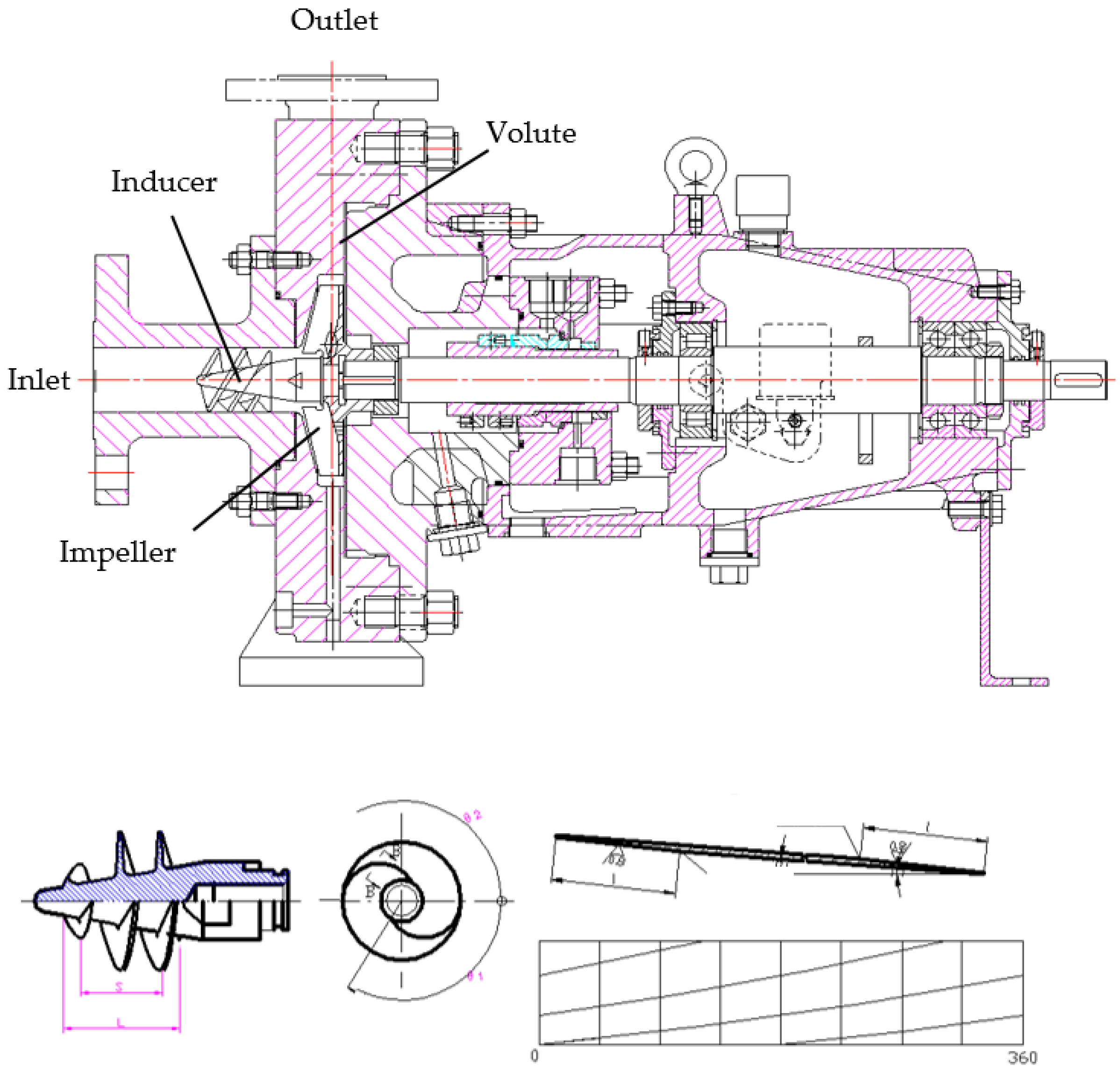
2.1. Main Parameters

A high-speed pump with a specific speed of 23.08 is selected to be researched here, and the inducer is designed into a two long- and two short-bladed pattern, which can be seen in Figure 1. The design parameters are given in Table 1.
The maximum outer diameter of the inducer is 38 cm. The number of centrifugal impeller blades is 8, and its blades are designed into the simplest straight blade form to minimize the influence of complex flow of centrifugal impeller on the inducer.

2.2. Experimental System

The closed test bench system of a centrifugal pump is set up, which is shown in Figure 2. The pump in this experiment is horizontally installed in the closed system, and a variable frequency motor is adopted. The variable frequency motor model is GBS-22-06E13. The rated output power is 22 KW. The rated frequency is 100 Hz, and the torque is 35 Nm. The volume of liquid storage tank is 31 m3, and vacuum pump is connected externally (the maximum vacuum degree can reach 6 × 10⁻² Pa) to change the pressure drop degree at the pump inlet.

3. Numerical Calculation Method

3.1. Calculation Area and Grid Layout

The three-dimensional entity of the whole flow field is shown in Figure 3. The calculation liquid area is composed of four parts. They are inlet pipe, splitter-bladed inducer (including TC layer), impeller, and volute. To improve the calculation accuracy, structured grids are adopted both in the inducer and the impeller flow area. The total number of calculation grids of the whole high-speed inducer centrifugal pump is 9,148,498, and its grid quality meets the solution conditions of the solver. The grids of the inducer and the impeller are the core parts, which are shown in Figure 4.

3.2. Validation of Grid Independence

The effect of six different densities of grid on the head was investigated under the design conditions. The results of the independent tests are shown in Figure 5. As can be seen, when the number of grid elements exceeds 9.15 million, the head changed by less than 0.1%.

3.3. Numerical Calculation Model

In order to explore the cavitation mechanism in the splitter-bladed inducer and the impeller, the cavitation flow is numerically calculated. During the simulation, a physical model is based on the assumption that the mixture of water and vapor in a cavitating flow is a homogeneous fluid. Reynolds average N–S approach is used for turbulent flow in this work. A mixture model is adopted, and the number of the phases is set as two. The two phases are considered as water and vapor [24,25]. As the inlet and outlet pressure is not lower than the saturation pressure, the vapor volume fraction is assumed to be zero at the inlet and at the outlet of the pump. The liquid phase is water under the standard condition. Equations of continuity and of momentum conservation are:
ρ t + x j ( ρ u j ) = 0
t ( ρ u j ) + x j ( ρ u i u j ) = P x i + x j ( μ u i x j )
with:
ρ = α w ρ w + α v ρ v
Volume fraction equation for the vapor phase is:
t ( α v ρ v ) + x i ( α v ρ v u ) = x i ( α v ρ v u d r , v )
The above equations are formulated in terms of the mass-averaged mixture velocity u and drift velocity of the vapor phase udr,v, which are defined as the following, respectively:
u = α w ρ w u w + α v ρ v u v ρ
u d r , v = ( ρ ρ v ) d v 2 18 μ c f · [ g ( u v · u v ) ] 1 ρ i = 1 n a i ρ i u w i
in which n is phase number. In the present simulation, n = 2. ai represent the volume fraction of the i phase. f is given below:
f = { 1 + 0.05 R e 0.687   , R e < 1000 0.018 R e ,                                 R e 1000
Normal speed is specified at the inlet, vinlet = 0.8842 m/s. Static pressure is specified at the outlet, Poulet = 1.00818 × 10⁶ Pa. No slip boundary condition is specified at wall. The moving coordinate system is specified on the inducer and the impeller, with n = 6000 r/min. The static coordinate system is specified on the inlet pipe and the volute. The “transient rotor-stator” type is selected to specify the interfaces where the inlet pipe-inducer and the inducer-volute interfaces are located. Simulations on the centrifugal pumps with five inducers are calculated in the ANSYS-CFX software.
In cavitation calculation, the inlet boundary condition is set as the total pressure inlet, which is consistent with the test, its value is 15,590 Pa, and the outlet is set as the mass flow rate, which is 0.88 m/s. In order to speed up convergence, the steady file without cavitation is taken as the initial file. The interface between the rotor and the stator and between the rotor and the inlet section is set to the frozen rotor mode, and the transient frozen rotor mode is set for unsteady calculation. The time step of unsteady cavitation calculation is set to 2 × 10⁻⁴ s. Except for the inducer and impeller rotor components, other components are set as the static region. The volute chamber is set as Counter Rotating Wall, and the convergence accuracy of static and unsteady calculation is 10−4 relative to the static domain.

4. Numerical Calculation and Analysis of Test Results

4.1. Reliability Analysis of Numerical Calculation Results

The centrifugal pump with a tip clearance (TC) of 0.2 mm is selected for experimental research and numerical calculation. The obtained external characteristic curves are shown in Figure 6.
The following conclusions can be drawn from Figure 6: (1) The H–Q curve obtained by numerical calculation and that obtained by experimental measurement have the same basic trend. (2) The splitter-bladed inducer has a slight positive slope under a small flow rate, which means that it is slightly unstable under a small flow rate, but the phenomenon is not particularly obvious. (3) The head obtained by numerical simulation is slightly higher than the measured results. The largest difference is 0.5 m, and the relative errors are all within 0.7%. This shows that the numerical results are consistent with the measured results, and the relative errors are small. (4) The η–Q curve obtained by numerical calculation is also consistent with that obtained by experimental measurement. The efficiency value obtained by numerical calculation is higher than that obtained by experiment. The efficiency point with the largest difference is 0.6, and its relative error is 2.3%. The reason for the large relative error is that many actual situations are ignored in the numerical calculation, such as the loss in the pipeline, the loss caused by the coordination error, etc. This error can be taken as a systematic error to realize the prediction data of this high-speed centrifugal pump in the numerical calculation. Through the comparison and analysis of numerical calculation and experimental measured values, it shows that numerical calculation can predict the performance of the high-speed centrifugal pump, and the results of numerical calculation under different TC in this paper are credible.

4.2. Analysis of Calculation Results under Different Tip Clearance

In order to study the influence of different TC on the performance of the pump, eight tip clearances of 0.1, 0.2, 0.3, 0.4, 0.5, 0.8, 1.5, and 2.0 mm were designed by expanding the pipe diameter. In order to a study the flow and cavitation mechanism in the tip clearance, a cylindrical surface is selected. The surface is near the tip clearance, which can contain complete cascade expansion of the inducer as much as possible. The cylindrical surface is located at the position where the outer wall diameter ratio is 0.92211, as shown in Figure 7.
Through numerical calculation, the head distribution diagrams under 8 tip clearance conditions are obtained, which is drawn in Figure 8.
The following conclusions can be drawn from Figure 8: (1) When TC = 0.3 mm, the head of the pump is the highest. (2) In the range of 0.1 mm ≤ TC ≤ 0.52 mm, the pump runs in a high head area. When 0.1 mm ≤ TC ≤ 0.3 mm, its head increases with the increase in the tip clearance. When 0.3 mm ≤ TC ≤ 0.52 mm, its head decreases with the increase in the tip clearance. (3) When TC ≥ 0.52 mm, the head decreases continuously. From above, it can be seen that TC has a certain effect on the head of the high-speed centrifugal pump with a splitter-bladed inducer. When TC is in a small range, the clearance leakage is small. TC has a little impact on the head of the pump, and the pump runs in a higher performance area. However, the leakage increases with the increase in the tip clearance, and the head of the pump is greatly affected. Large TC makes the head of the pump drop quickly.
The cylindrical surface shown in Figure 7 is expanded to analysis the distribution of the static pressure and vapor volume fraction in the inducer cascade flow passage. The static pressure and vapor volume fraction distributions are shown in Figure 9 and Figure 10, respectively. Table 2 shows the maximum vapor volume fraction and cavitation area.
The following four conclusions can be drawn from Figure 9: (1) When TC = 0.1 ~ 2.0 mm, the lowest static pressure is located on the suction surface of the long blades, mainly on the outer edge near the inlet. The highest pressure is located on the blades near the hub. (2) When TC changes from 0.1 mm to 0.4 mm, the lowest pressure area at the outer edge of the long blades gradually increases. (3) When TC changes from 0.5 mm to 2.0 mm, the static pressure area on the long blades gradually decreases. (4) With the increase in tip clearance, the maximum pressure decreases gradually, and the pressure value in the inducer’s passage also decreases gradually.
Figure 10 shows the vapor volume fraction distribution. Table 2 lists cavitation area. The following results can be concluded from Figure 10 and Table 2: (1) At TC = 0.1 ~ 2.0 mm, cavitation occurs at the outer edge of the long blades of the inducer near the inlet. (2) When TC is in the range of 0.1 ~ 0.4 mm, the vapor volume fraction at the outer edge of the long blades increases with the increase in TC, which means that the cavitation increases with the increase in TC. (3) When TC is in the range of 0.5 ~ 2.0 mm, the vapor volume fraction at the outer edge of the long blades gradually decreases, and the cavitation phenomenon is suppressed.
From above, it can be seen that the results of Figure 9 and Figure 10 are consistent. TC has a certain influence on the static pressure distribution in the splitter-bladed inducer; when TC is within a certain range (less than 0.5 mm in this case), the increase in TC will aggravate the cavitation of the inducer’s outer edge. When TC exceeds this certain range, the increase in the clearance will inhibit the cavitation of the outer edge. However, when TC is too large, the outlet pressure will drop sharply. Figure 9h shows that the pressure at the outlet of the inducer is obviously lower than that of other tip clearances. This pressure will affect the pressure at the adjacent watershed, i.e., the inlet of the impeller [6].
The main reason that this phenomenon occurs in Figure 9 and Figure 10 can be analyzed as below: (1) TC is in a small range. The amount of leakage from the gap is large, the pressure is released, and the area of the low-pressure area will increase. (2) TC is in a larger range. As the gap becomes larger, the leakage becomes larger, and the pressure drop is more obvious. The maximum pressure also shows a downward trend. At the same time, as there is no blockage at the gap, the liquid flows smoothly, and the bubbles generated by cavitation can disappear quickly with the axial rotation. This situation improves some cavitation performance.
In order to analyze the cavitation situation more deeply, the volume fraction of 0.1 distribution on ISO surface under each TC was analyzed. The distributions are shown in Figure 11.
The following conclusions can be obtained from Figure 11: (1) When TC ≤ 0.3 mm, the cavitation of the inducer is mainly concentrated at the outer edge of the long blades near the inlet, and the cavitation area does not change very much with the increase in the tip clearance. (2) When 0.3 mm < TC < 0.5 mm, the cavitation area on the long blades continues to become shorter. (3) When TC ≥ 0.5 mm, cavitation changes to a certain extent; the cavitation area on the long blades continues to decrease, but the cavitation also appears on the outer edge of the short blades near the inlet. (4) When TC reaches 2.0 mm, the cavitation area on the long blades continues to decrease, while the cavitation area at the short blades increases, and a small amount of cavitation appears at the root of the blades near the outlet. Thus, the size of the cavitation is closely related to the tip clearance.
As cavitation is closely related to the leakage vortex, the distributions of streamline and vorticity at different TC are analyzed in this paper, which are shown in Figure 12 and Figure 13, respectively.
The following conclusions can be obtained from Figure 12: (1) Under the condition of every tip clearance, leakage vortex all occur at the outer edge of the long blades’ inlet. (2) The leakage vortex at the inlet of the long blades decreases with the increase in the tip clearance. (3) With the increase in TC, the leakage vortex stretches from the suction surface to the pressure surface of the long blades, and then to the suction surface of the short blades. Therefore vortex flow occurs at the flow channel between the long and the short blades. (4) When TC is increased, the velocity in the tip clearance decreases gradually, and the leakage and backflow in the tip clearance decreases too. The main reason is that when TC is small (0.1 mm), only a small amount of fluid can flow through the clearance. When TC increases to 0.2 mm, the blockage appears in the tip clearance and fluid accumulates at the clearance. As the fluid continues to increase, the blockage grows serious. The fluid will continue to fill the tip clearance, which will cause more blockage. When TC increases to more than 1.5 mm, the blockage at the clearance is relieved, and the fluid can directly flow through the larger tip clearance without blockage. Thus, the size of TC has a great effect on the velocity in the tip clearance of the long blades, while the size of clearance has little effect on the velocity in the tip clearance of the short blades.
The following conclusions can be drawn from Figure 13: (1) The leading edge of the blades is the position where vorticity is concentrated. (2) When TC is 0.1 mm, the vorticity is mainly distributed at the leading edge and the hub of the long blades. There is a small amount of vorticity at the leading edge of the short blades. The vorticity at the long blades will move downstream, along with the direction of the inducer rotation. Due to the existence of tip clearance, the leakage vortex does not gather in a large amount in the TC area, and the vorticity in the clearance appears in the form of vortex filaments. (3) When TC is increased to 0.2 mm, a small amount of vorticity will appear at the hub of the inducer, and the leakage vortex will become larger at the short blades’ clearance. Compared with TC of 0.1 mm, the distribution position of vorticity at the inducer moves downstream, and the vorticity becomes larger. (4) When TC is increased to 0.3 mm, the vorticity at the tip clearance of the long blades becomes smaller, while the vorticity at the hub becomes larger. (5) When TC is from 0.3 mm to 0.4 mm, the filamentous vorticity at the clearance disappears, and the vorticity at the hub decreases. (6) When TC is from 0.4 mm to 0.5 mm, the vorticity at the clearance and hub increases, and the vorticity at the short blades clearance decreases with the increase in the tip clearance. When TC is increased to 0.8 mm, the vorticity is concentrated at the long blades’ clearance, and the vorticity there becomes thicker. The vorticity at the hub becomes larger, and the vorticity at the short blades’ clearance changes less. (7) When TC is increased to 1.5 mm, the vorticity at the clearance and the leading edge of the long blades decreases. The vorticity at other positions changes obviously. There is only a small amount of vorticity at the short blades’ rim. (8) When TC is increased to 2.0 mm, the vorticity at many positions disappears, and vorticity exists only at the leading edge of the short blades and the hub.

5. Conclusions

In this paper, cavitation in a centrifugal pump with a splitter-bladed inducer is studied experimentally and numerically. In the simulation, the centrifugal pump with a splitter-bladed inducer was simulated under eight different tip clearance conditions by using structural grid, RNG turbulence model, and R-P cavitation model. The following conclusions were obtained through research:
(1) The tip clearance has a certain effect on the head of the centrifugal pump with a splitter-bladed inducer. When the tip clearance is in a small range, the clearance leakage is small. It has little impact on the head of the pump, and it can make the pump run in a higher performance area. However, with the increasement in the tip clearance, the leakage increases. It has a great impact on the head of the pump, and it makes the head of the pump drop quickly.
(2) Tip clearance has a certain effect on the static pressure distribution in the flow passage of the splitter-bladed inducer cascade. When the tip clearance is within a certain range, the increasement in tip clearance will aggravate the cavitation at outer edge near the long blades’ inlet. When the tip clearance exceeds this certain range, the increasement in the tip clearance will inhibit the cavitation at the outer edge. However, it will also make the outlet pressure drop sharply and affect the pressure at the inlet of the impeller.
(3) The severity of cavitation is closely related to the tip clearance. In the case of small clearance, the cavitation of the inducer is mainly concentrated at the outer edge of the long blades near the inlet. When the tip clearance increases to a certain value, the cavity area at the long blades becomes shorter, but the cavitation also appears at the outer edge of the short blade near the inlet. With the increasement in the clearance, the cavitation at the short blade becomes serious, and a small amount of cavitation also appears at the root of the blade near the outlet.
(4) Tip clearance has an effect on the magnitude and position of vorticity. The leakage vortex at the long blade clearance of the inducer will decrease and move backward with the increasement in TC. The flow blockage at the clearance will be alleviated with the increasement in the clearance. First, the leakage at the clearance of short blades becomes stronger, and then it becomes weaker with the increasement in TC. Vorticity at the outer edges of the blades near the inlet is greatly affected by the change of TC. When TC becomes small, the vorticity at outer edge of the blades near the inlet degrades quickly.
The research results of this paper can provide theoretical basis and technical support for the design of the inducer’s tip clearance.

Author Contributions

Writing—original draft preparation and experiment, X.G.; simulation, S.Y.; simulation, X.L.; data curation, L.S.; supervision, E.H.; supervision, Z.Z. All authors have read and agreed to the published version of the manuscript.

Funding

This research was funded by Science Foundation of China (No. 51976202); Key Research and Development Program of Zhejiang Province (2021C03019).

Conflicts of Interest

The authors declare no conflict of interest.

References

  1. Shuai, L. Influence of Tip Clearance on the Flow and Cavitation Characteristics of Inducer; Zhejiang University of Technology: Hangzhou, China, 2017. [Google Scholar]
  2. Kaibin, N. Numerical Analysis of Backflow Catitation in Inlet of Centrifugal Pump with Inducer; Xi’an University of Technology: Xi’an, China, 2010. [Google Scholar]
  3. Guo, X.; Zhu, Z.; Cui, B.; Huang, Y. Anti-cavitation performance of a splitter-bladed inducer under different flow rates and different inlet pressures. Sci. China-Technol. Sci. 2015, 58, 2131–2138. [Google Scholar] [CrossRef]
  4. Guo, X.; Zhu, Z.; Cui, B.; Li, Y. The Rotating Cavitation Performance of a Centrifugal Pump with a Splitter-Bladed Inducer under Different Rotational Speed. Int. J. Turbo Jet-Engines 2015, 32, 275–283. [Google Scholar] [CrossRef]
  5. Guo, X.; Zhu, Z.; Cui, B.; Li, Y. Effects of the short blade locations on the anti-cavitation performance of the splitter-bladed inducer and the pump. Chin. J. Chem. Eng. 2015, 23, 1095–1101. [Google Scholar] [CrossRef]
  6. Guo, X.; Zhu, L.; Zhu, Z.; Cui, B.; Li, Y. Numerical and experimental investigations on the cavitation characteristics of a high-speed centrifugal pump with a splitter-blade inducer. J. Mech. Sci. Technol. 2015, 29, 259–267. [Google Scholar] [CrossRef]
  7. Guo, X.; Zhu, Z.; Cui, B.; Shi, G. Effects of the number of inducer blades on the anti-cavitation characteristics and external performance of a centrifugal pump. J. Mech. Sci. Technol. 2016, 30, 3173–3181. [Google Scholar] [CrossRef]
  8. Guo, X.; Zhu, Z.; Shi, G.; Huang, Y. Effects of rotational speeds on the performance of a centrifugal pump with a variable-pitch inducer. J. Hydrodyn. 2017, 29, 854–862. [Google Scholar] [CrossRef]
  9. Song, M.; Xie, H.; Yang, B.; Zhang, S. Influence of Tip Clearance on Flow Characteristics of Axial Compressor. Processes 2020, 8, 1445. [Google Scholar] [CrossRef]
  10. Shen, S.; Qian, Z.; Ji, B.; Agarwal, R.K. Numerical investigation of tip flow dynamics and main flow characteristics with varying tip clearance widths for an axial-flow pump. Proc. Inst. Mech. Eng. Part A J. Power Energy 2019, 233, 476–488. [Google Scholar] [CrossRef]
  11. Xu, B.; Shen, X.; Zhang, D.; Zhang, W. Experimental and numerical investigation on the tip leakage vortex cavitation in an axial flow pump with different tip clearances. Processes 2019, 7, 935. [Google Scholar] [CrossRef] [Green Version]
  12. Xu, Y.; Tan, L.; Liu, Y.; Cao, S. Pressure fluctuation and flow pattern of a mixed-flow pump with different blade tip clearances under cavitation condition. Adv. Mech. Eng. 2017, 9, 1687814017696227. [Google Scholar] [CrossRef]
  13. Dreyer, M.; Decaix, J.; Muench-Alligne, C.; Farhat, M. Mind the gap: A new insight into the tip leakage vortex using stereo-PIV. Exp. Fluids 2014, 55, 1849. [Google Scholar] [CrossRef]
  14. Li, W.; Yang, Y.; Shi, W.; Zhao, X.; Li, W. The Correction and Evaluation of Cavitation Model considering the Thermodynamic Effect. Math. Probl. Eng. 2018, 2018, 7217513. [Google Scholar] [CrossRef] [Green Version]
  15. Li, Y.; Yuan, S.; Lai, H. Numerical Study of Unsteady Flows with Cavitation in a High-Speed Micro Centrifugal Pump. J. Therm. Sci. 2017, 26, 18–24. [Google Scholar] [CrossRef]
  16. Yang, X.; Qin, Y.; Qu, Z. Leakage Loss Study of a Synchronal Rotary Multiphase Pump With a Full Range of Inlet Gas Volume Fractions. J. Fluids Eng. Trans. ASME 2016, 138, 071301. [Google Scholar] [CrossRef]
  17. Campos-Amezcua, R.; Khelladi, S.; Mazur-Czerwiec, Z.; Bakir, F.; Campos-Amezcua, A.; Rey, R. Numerical and experimental study of cavitating flow through an axial inducer considering tip clearance. Proc. Inst. Mech. Eng. Part A J. Power Energy 2013, 227, 858–868. [Google Scholar] [CrossRef]
  18. Hong, S.; Kim, D.; Kim, J.; Choi, C.; Kim, J. Study on inducer and impeller of a centrifugal pump for a rocket engine turbopump. Proc. Inst. Mech. Eng. Part C J. Mech. Eng. Sci. 2013, 227, 311–319. [Google Scholar] [CrossRef] [Green Version]
  19. Okita, K.; Ugajin, H.; Matsumoto, Y. Numerical Analysis of the Influence of the Tip Clearance Flows on the Unsteady Cavitating Flows in a Three-Dimensional Inducer. J. Hydrodyn. 2009, 21, 34–40. [Google Scholar] [CrossRef]
  20. Kim, S.; Choi, C.; Kim, J.; Park, J.; Baek, J. Tip Clearance Effects on Cavitation Evolution and Head Breakdown in Turbopump Inducer. J. Propuls. Power 2013, 29, 1357–1366. [Google Scholar] [CrossRef]
  21. Kim, C.; Kim, S.; Choi, C.; Baek, J. Effects of inducer tip clearance on the performance and flow characteristics of a pump in a turbopump. Proc. Inst. Mech. Eng. Part A J. Power Energy 2017, 231, 398–414. [Google Scholar] [CrossRef]
  22. Yanxia, F.; Jianping, Y.; Shouqi, Y.; Pace, G.; D’Agostino, L. Effect of Tip Clearance on the Internal Flow and Hydraulic Performance of a Three-Bladed Inducer. Int. J. Rotating Mach. 2017, 2017, 2329591. [Google Scholar]
  23. Torre, L.; Pasini, A.; Cervone, A.; Pace, G.; Miloro, P.; D’Agostino, L. Effect of Tip Clearance on the Performance of a Three-Bladed Axial Inducer. J. Propuls. Power 2011, 27, 890–898. [Google Scholar] [CrossRef]
  24. Ji, B.; Luo, X.; Wu, Y.; Peng, X.; Duan, Y. Numerical analysis of unsteady cavitating turbulent flow and shedding horse-shoe vortex structure around a twisted hydrofoil. Int. J. Multiph. Flow 2013, 51, 33–43. [Google Scholar] [CrossRef] [Green Version]
  25. Ji, B.; Luo, X.; Arndt, R.E.A.; Wu, Y. Numerical simulation of three dimensional cavitation shedding dynamics with special emphasis on cavitation-vortex interaction. Ocean. Eng. 2014, 87, 64–77. [Google Scholar] [CrossRef]
Figure 1. High speed inducer centrifugal pump.
Processes 09 01576 g001
Figure 2. Closed test bench system of a high-speed inducer centrifugal pump.
Processes 09 01576 g002
Figure 3. Calculation area.
Processes 09 01576 g003
Figure 4. Local area grid of the inducer and the impeller.
Processes 09 01576 g004
Figure 5. The head curve as a function of the number of grid elements.
Processes 09 01576 g005
Figure 6. Comparison of External Characteristic Curves.
Processes 09 01576 g006
Figure 7. Position of the expansion surface of the inducer cascade.
Processes 09 01576 g007
Figure 8. Head of the Centrifugal Pump under Various Tip Clearance Conditions.
Processes 09 01576 g008
Figure 9. Pressure distribution in the passage between blades.
Processes 09 01576 g009
Figure 10. Vapor volume fraction distribution in the passage between blades.
Processes 09 01576 g010
Figure 11. ISO surface distribution of volume fraction of 0.1 under each TC.
Processes 09 01576 g011
Figure 12. Streamline for λ2 Criteria Shading for Each TC.
Processes 09 01576 g012
Figure 13. Vorticity Diagram of Inducer Region for Each Clearance.
Processes 09 01576 g013
Table 1. The design parameters.
Rotation Speed
n (r/min)
Flow Rate
Q (m3/h)
Head
H (m)
Specific Speed
ns
Inducer Blades
6000410023.084
Table 2. Maximum Vapor Volume Fraction and Cavitation Area.
TC (mm)0.10.20.30.40.50.81.52.0
Maximum vapor volume fraction0.5530.8420.8890.8850.8880.8540.8540.663
Cavitation area (mm2)50.7663.0147.2351.6452.3616.3920.4827.95
Publisher’s Note: MDPI stays neutral with regard to jurisdictional claims in published maps and institutional affiliations.

