Article

Feedback Control of Melt Pool Area in Selective Laser Melting Additive Manufacturing Process

1
Department of Mechatronics and Biomedical Engineering, Air University, Islamabad 44000, Pakistan
2
Department of Mechanical Engineering, Khwaja Fareed University of Engineering & Information Technology, Rahim Yar Khan 64200, Pakistan
3
Department of Engineering, School of Science and Technology, Nottingham Trent University, Nottingham NG11 8NS, UK
*
Author to whom correspondence should be addressed.
Processes 2021, 9(9), 1547; https://doi.org/10.3390/pr9091547
Submission received: 13 August 2021 / Revised: 25 August 2021 / Accepted: 25 August 2021 / Published: 30 August 2021
(This article belongs to the Special Issue New Frontiers in Magnetic Polishing and Electrochemical Technology)

Abstract

:
Selective laser melting (SLM), a metal powder fusion additive manufacturing process, has the potential to manufacture complex components for aerospace and biomedical implants. Large-scale adaptation of these technologies is hampered due to the presence of defects such as porosity and part distortion. Nonuniform melt pool size is a major cause of these defects. The melt pool size changes due to heat from the previous powder bed tracks. In this work, the effect of heat sourced from neighbouring tracks was modelled and feedback control was designed. The objective of control is to regulate the melt pool cross-sectional area rejecting the effect of heat from neighbouring tracks within a layer of the powder bed. The SLM process’s thermal model was developed using the energy balance of lumped melt pool volume. The disturbing heat from neighbouring tracks was modelled as the initial temperature of the melt pool. Combining the thermal model with disturbance model resulted in a nonlinear model describing melt pool evolution. The PID, a classical feedback control approach, was used to minimize the effect of intertrack disturbance on the melt pool area. The controller was tuned for the desired melt pool area in a known environment. Simulation results revealed that the proposed controller regulated the desired melt pool area during the scan of multiple tracks of a powder layer within 16 milliseconds and within a length of 0.04 mm reducing laser power by 10% approximately in five tracks. This reduced the chance of pore formation. Hence, it enhances the quality of components manufactured using the SLM process, reducing defects.

1. Introduction

Additive manufacturing (AM) of metal parts has the potential of producing complex and integrated designs with ease and the supplementary advantage of cost and weight reduction. There are many metal-based AM processes, but laser powder bed fusion (LPBF) imparts better density, strength, and geometric tolerance. Parts produced by the LPBF process are used in aerospace [1,2] and medical implants [3,4]. In LPBF, parts can be built using one of two techniques: selective laser melting (SLM) and electron beam melting (EBM) [5]. This work focused on the SLM process in which a metal powder is melted by a high power laser [6]. The SLM process starts by slicing a CAD design into thousands of layers according to the layer thickness. The powder is spread on the build plate and the layer is laser scanned according to a predefined laser scanning strategy in each layer. This sequence is repeated until all the layers are scanned [7]. A final part is welded to build a plate that is separated by conventional machining techniques. After the sintering of one layer is finished, a new thin layer of powder is spread on top, and then another cycle begins. However, there is no guarantee that parts manufactured by LPBF technologies will fulfill the structural requirement of a specific application.
Currently, the inability to guarantee specific material properties is holding back their adoption [8]. Defects in parts produced by SLM can be categorized as geometric or dimensional, mechanical, and physical [9]. All these defects are due to perturbation of the melt pool from nominal size; an undersized melt pool results in lack of fusion and related defects, such as delamination, and an oversized melt pool results in keyhole related defects such as porosity [10]. Continuously varying melt pool geometry also results in degraded micro structural properties such as grain size and morphology, and consequently mechanical properties such as yield strength and fatigue strength are weakened [11]. It has been realized that the use of control techniques to control the melt pool geometry is inevitable [12].
Various melt pool parameters such as length, width, depth, surface area, and cross-sectional area of the melt pool have been used for the control of melt pool geometry [13]. Earlier literature on AM control focused on the control of process parameters for direct energy deposition (DED), but recent researchers have been working on the process control of SLM process due to enhanced applications. The literature of the DED process presents the use of PID control, feedback control for clad height [14], predictive control for clad height and temperature [15], multivariable melt pool geometry and temperature control [16], feedforward control for clad height [17], model-based PI control to regulate temperature [18], and model-based feedforward control for part height [19]. In the DED, the powder deposition occurs via the deposition of a controlled amount of powder in the melt pool.
To maintain the melt pool geometry in DED, powder flow rate, laser power, and laser speed are the controlled inputs. Whereas SLM is a powder bed fusion process, and the most common manipulated parameter is laser power for maintaining melt pool geometry. In this regard, however, very few studies are seen in the literature. Such studies for SLM process control include repetitive control [20], iterative learning control [21], model-based feedforward control [22], and passivity-based iterative learning control [23]. In earlier work, Creagh et al., [24] used system identification to obtain a second order model for melt pool dynamics and the PI controller was used for melt pool regulation.
Ranken et al. [25], used sensor-based adaptive self-learning control for melt pool modulation for the SLM process. The same authors used model-based feedforward control using a finite element heat simulation in combination with feedback by the thermal sensor for temperature control of SLM [26]. In another work, the feedforward control strategy was used for temperature regulation of the SLM process [27]. These control systems can build parts with improved geometrical accuracy compared to an open loop process. However, they are unable to remove the effect of heat from previously scanned tracks in a layer and heat from layers scanned earlier. This work presents the melt pool model-based feedback control of SLM process which captured the melt pool dynamics by considering the effect of heat coming from previous tracks of a layer.
The SLM process was modelled in this study using a lumped parameter approach. The model incorporated the effect of heat in the form of energy from previous tracks. This approach was originally developed by Doumanidis and Kwak [28] for modelling of direct energy deposition (DED), and Wang et al. [22] modified the feed model forward control of SLM. The lumped parameter model in SLM is based on the conservation of energy principle whereas, in DED, Doumanidis and Kwak [28] used the conservation of mass and energy principle. In both models, the temperature of the first track is taken as the initial temperature of the chamber. This initial temperature increases during the laser scanning due to energy coming from previously scanned tracks and increases the lumped temperature of the melt pool. High melt pool temperature varies the melt pool dimensions and reduces part quality.
The effect of energy coming from previous tracks was modelled as a transient moving heat source solution [29]. This solution neglected the heat loss from the substrate surface due to convection, conduction, and radiation. In this paper, simulation results of the feedback control of a melt pool cross-sectional area of SLM based on linearization of lumped parameter model of melt pool are presented. The initial temperature of later tracks was modelled by considering the moving heat source solution on the plate surface. The remainder of this paper is structured as follows. In Section 2, the lumped model of the SLM system is given that describes melt pool geometry, the energy balance of melt pool volume, and the periodic variation of initial temperature in a layer. In Section 3, the feedback control scheme is synthesized. In Section 4, the results of simulations are presented and discussed. Conclusions are given in Section 5.

2. Modelling

In this section, a model for the thermal melt pool dynamics is presented based on the heat conduction equation in the build part. The model was subsequently linearized at steady-state melt pool conditions. The model was based on the lumped parameter approach and energy balance of the melt pool. To increase the fidelity of the model, a disturbance model was added to process dynamics to account for the neglected thermal interactions. The model gives an understanding of exactly how the structured disturbances impact the dynamic system. In the following subsections, the geometrical model of the melt pool and the disturbance model are developed.

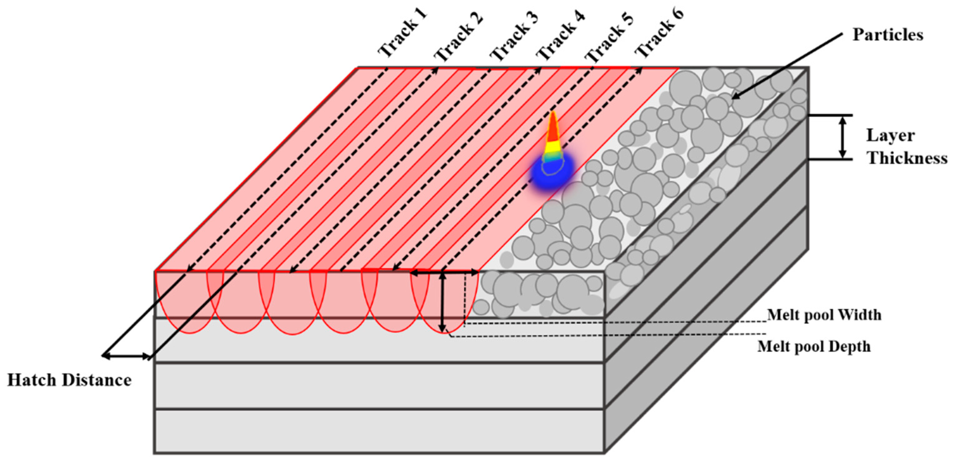
2.1. Analytical Lumped Parameter Model for Melt Pool Geometry

There are many models for melt pool developed in the literature [14,18,30,31,32], and these models describe the melt pool details for laser cladding or the material deposition additive manufacturing process. Analytical control-oriented models of the selective laser melting process are rare in the literature. In this work, a mathematical model based on the lumped parameter approach reported by Wang et al. [22] has been implemented but the effect of heat coming from previous tracks has been modelled by a transient moving heat source solution [29] instead of a steady-state moving heat source solution. This analytical model was used to describe the laser and metal powder interaction and was subsequently used for model-based feedback control and heat disturbance rejection in the SLM process.
The model provides a dynamic description of the molten puddle, expressed in terms of laser power, melt pool cross-sectional area, and laser heat source motion. The laser scans different tracks in any layer according to the hatch scheme as shown in Figure 1, which also depicts important process parameters such as hatch spacing, layer thickness, and melt pool parameters such as width and depth. There is a solid substrate below the current layer, melted and unmelted powder. The conservation of energy principle was applied to a melt pool puddle of ellipsoidal shape. The rate of internal energy accumulation in the puddle is equal to the difference of the power inflow by input laser and outflow due to the solidification of material and the external heat transfer rate from the surface of the control volume.

2.2. Energy Balance of Melt Pool Volume

The model is based on the first law of thermodynamics applied to the ellipsoidal control volume of the melt pool. The rate of change of energy of ellipsoidal volume is equal to the power added by a laser source and power loss due to material solidification, convection conduction, and radiation as described by Equation (1).
d d t ( ρ V ( t ) e ( t ) ) = ρ A ( t ) ν   ( t ) e b η Q ( t ) A s α s   ( T ( t ) T i n i t ) A G α G   ( T ( t ) T a ) A G ε σ ( T 4 ( t ) T a 4 )
The term on the right hand is the rate of change of energy of contents of the melt pool. The left hand side represents how this change is brought about. In Equation (1), e ( t ) represents the specific internal energy of the melt pool. Product of powder density ρ and melt pool volume V ( t ) is the mass of powder in the ellipsoidal melt pool. The specific internal energy e ( t )   is measured with respect to ambient temperature,   T a   as shown in Equation (2). T m is melting temperature and c s   and c l are the specific heat capacity of solid and liquid states, while h S L is the latent heat of fusion.
e ( t ) = c s   ( T m T a ) + h S L + c l ( T ( t ) T m )
The first term on the right hand side of Equation (1) is the power lost during solidification or material leaving the melt pool. The product of ρ ,   A ( t ) and ν   ( t ) denotes the rate of mass solidified and e b is the specific energy of the solidified material, given as Equation (3).
e b = c s   ( T m T i n i t )
The other three terms on the right hand side of Equation (1) represent the total thermal power exchange at the melt pool boundaries. Q is the input laser power acting at the top surface of the melt pool and the other terms are loss of power by conduction to the substrate, loss by convection, and radiation from the free surface, respectively. A ( t ) , denotes the maximum cross-sectional area of the melt pool, A G represents the area of the melt pool interface with the substrate and A S is the melt pool interface with the free surface. σ = 5.67 × 10 8 W/(m2·K4) is the Stefan–Boltzmann constant.   α s   , is the convective heat transfer coefficient, and α G is the conductive heat transfer coefficient modelled as convection. T i n i t in Equations (1) and (3) represents the initial (or prescan) temperature, of the track just before the laser strikes a particular point in a track. T i n i t is equal to T a for the first track, but for the second track and onwards this temperature is changed due to the power coming from previously scanned tracks.

2.3. Model Reduction

The melt pool model described by Equations (1)–(3) was reduced using the following assumptions. This model simplification is to distil the essential model structure and to increase understanding of the model.
a.
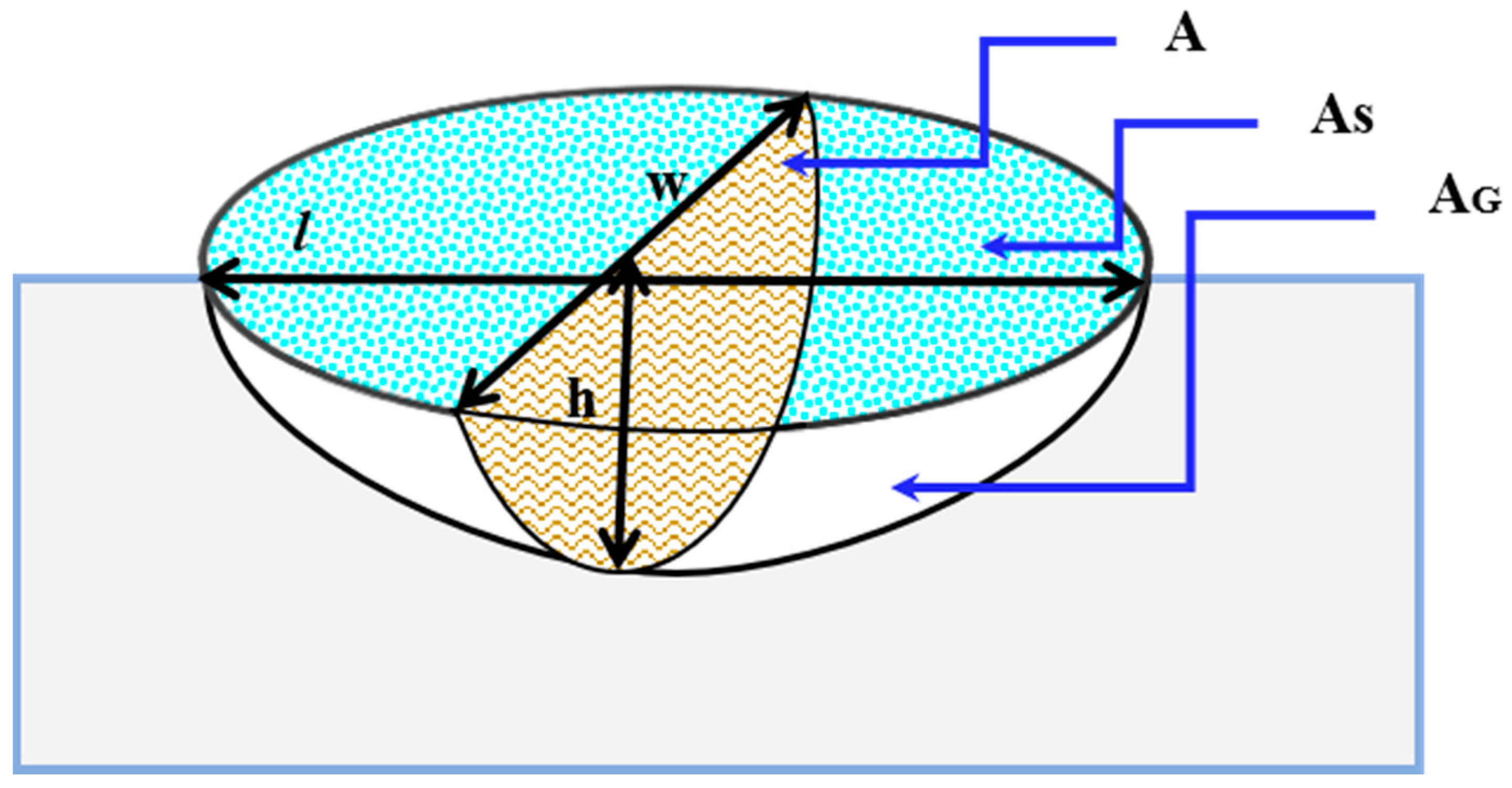
The melt pool shape is assumed to be a half 3D ellipsoid as shown in Figure 2. If l , w , and d are the length, width, and depth of half ellipsoid, then the volume and cross-sectional area of the melt pool are given by V ( t ) = ( π 6 ) w ( t ) d ( t ) l ( t ) and A ( t ) = ( π 4 ) w ( t ) d ( t ) , respectively. The area of the melt pool interface with the substrate is given by A G = π 2 3 ( w d l ) 2 3 and the area of the melt pool top surface is given by A S = ( π 4 ) w l .
b.
These volumes and areas are further simplified by considering the constant width to length ratio of the melt pool defined as β = l w and the constant width to depth ratio of the melt pool defined as = w d .
Melt pool volume V ( t ) interfaces with the area of top free surface A S , and interfaces with the substrate A S are further expressed in terms of r and β as:
V ( t ) =   λ A 3 2 ( t ) where λ = 4 3 ( r / π ) 1 2 β , and
A s ( t ) =   λ S A ( t ) where λ S = 2 5 3 r 1 3 β 2 3 , and
A G ( t ) =   λ G A ( t ) where λ G = r β .
c.
Melt pool temperature T ( t ) changes much faster than melt pool volume, so it is assumed that temperature T ( t ) reaches steady-state temperature T s s   and can be modelled with a constant percentage μ times the melting temperature T m as given in Equation (4).
T s s   T m   = μ T m
The value of this constant factor μ depends on the type of powder used for the SLM process. By substituting Equations (2) and (3) in Equation (1) along with the geometric variable definition described above, Equation (5) is obtained.
3 2 λ ρ e A 1 2 ( t )   d A ( t ) d t = ρ A ( t ) ν   ( t ) e b η Q ( t ) A s α s   ( T ( t ) T i n i t ) A G α G   ( T ( t ) T a ) A G ε σ ( T 4 ( t ) T a 4 )  
Equation (5) is expressed in functional form, as given in Equation (6), to reiterate the fact that the rate of change of melt pool area is the function of T i n i .
d A ( t ) d t = f ( A ( t ) , T i n i ) + g ( A ( t ) ) . Q ( t )
where f ( A ( t ) , T i n i ) and g ( A ( t ) ) are further elaborated in Equations (7) and (8).
f ( A ( t ) , T i n i t ) = ( 3 2 λ ρ e ) 1 { ρ ν   c s ( T m T i n i t ) + λ s α s [ ( 1 + μ ) T m T i n i t ] + λ G α G [ ( 1 + μ ) T m T a ] + λ G ε σ [ ( 1 + μ ) 4 T m 4 T a 4 ] } A 1 2  
g ( A ( t ) ) = ( 3 2 λ ρ e ) 1 · η A 1 2  
Equations (6)–(8) represent the reduced model of the melt pool area of SLM where Tinit is described if needed.

2.4. Disturbance Model

SLM parts with an overhanging feature are challenging to build. In the overhanging section of the part, heat is accumulated due to the poor thermal conductivity of the underlying powder. As a result, melt pool size, cooling, and solidification rates increase [33,34], which ultimately affects the microstructure of the part. Due to the higher energy density of laser and slow cooling rates residual stress is generated and results in defects such as warping [35] and loss of corner [10].
From the experiments in the literature, it is observed that the geometry of the melt pool is increased due to heat accumulated from previously scanned layers and tracks, which will cause the current track to be scanned preheated by the heat accumulated in the existing part. For a multitrack build illustrated in Figure 3, the initial (prescan) Temperature T i n i t at a point of interest, for example in track 6, is shown in Figure 3 with coordinates (x, y, z) equal to the ambient temperature plus the summation of temperature contributions from all past tracks. The computation of T i n i t   is briefly summarized as follows.
T i n i t is changed due to the energy coming from previous tracks and is modelled, given as Equation (9), using the transient moving point heat source solution developed by Carslaw and Jaeger [29] with the assumptions of no radiant loss, no melting, and constant thermal properties over the temperature range concerned. The heat loss from the substrate surface due to convection, conduction, and radiation is, however, already included in the energy balance equation. In Equation (9), ‘t’ is the current time, t is previous time, and x, y, and z are the corresponding distances from the laser source.
T i n i t = T o + P η 2 ρ C p ( π κ ) 3 2 0 t e x p [ ( x V ( t t ) ) 2 + ( y y 0 ) 2 + ( z z 0 ) 2 4 x ( t t ) ] ( t t ) 3 2 d t  
The temperature solution can be further derived by integrating t from 0 to t as given in Equation (10).
T i n i t = T o + P η 2 R k t ( π ) 3 2 e x p ( V x 2 κ ) ξ = R 2 π y e x p [ ξ 2 ( V 2 R 2 16 κ 2 ξ 2 ) ] d ξ
where R = ( x   x 0 ) 2 + ( y   y 0 ) 2 + ( z   z 0 ) 2 , t is the current time, t is previous time, x, y, and z are the corresponding distances from the laser source, and ξ is an integration variable that leads to the concise expression.

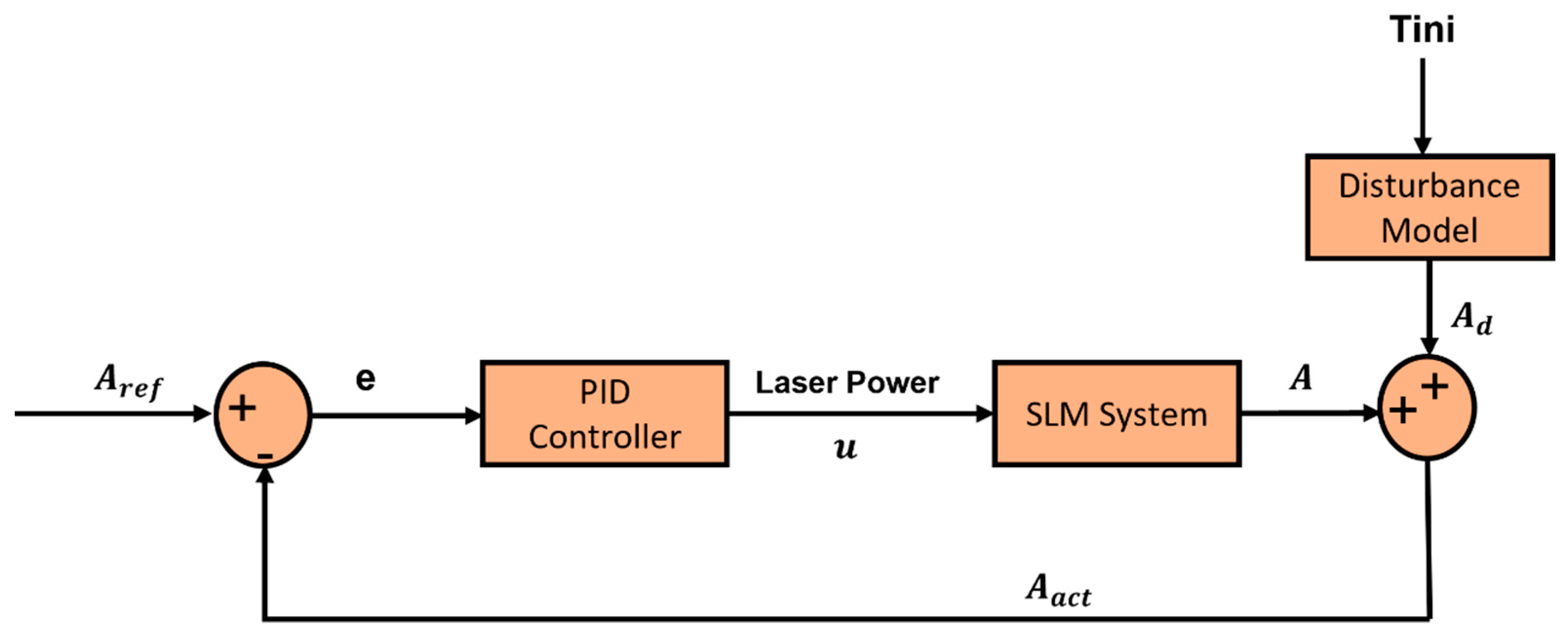
3. Controller Design

This section presents the state feedback PID controller designed using the linearized analytical model of the thermal melt pool dynamics, presented in the previous section.

3.1. Problem Formulation

The goal was to design a feedback-controlled close loop system that regulates the melt pool area by adjusting the laser power. The control problem was formulated as follows. Assume that the laser power Q in sintering is the only control variable, with other process parameters fixed. The control objective was to regulate Q(t) in each track such that a melt pool cross-sectional area is kept constant.

3.2. Control Scheme

The proposed control scheme comprises a proportional–integral–derivative (PID) controller to maintain the melt pool area at a specified set point by adjusting the laser power. The PID controller was selected as this was the simplest classical feedback, yet a powerful controller used in industrial applications. The controller was designed such that it maintained the melt pool cross-sectional area overcoming the disturbing heat with minimum settling time and overshoot. The PID controller was designed and implemented in a MATLAB® environment for the system such that it controlled the laser power to achieve the desired area minimizing error in that area. PID control was implemented using a feedback system that formed a closed loop. The control law is synthesized as given in Equation (11).
u = K p e + K i   e + K d d e d t
where e is given as Equation (12) having A r e f (Desired melt pool area) and A a c t (Actual melt pool area) at a time instant.
e = A r e f A a c t
The actual melt pool area is computed, given in Equation (13), as the sum of the area generated by the disturbing temperature from the previous tracks ( A d ) and the melt pool area developed by the laser itself at the current instant (A).
A a c t = A + A d
The controller was implemented tuning the gains: Proportional gain K p , Integral gain K i , and Derivative gain K d . All three control modes (Proportional–Integral–Derivative), when combined enable the controller to produce no steady-state error. This also enabled the system to be oscillation-free. The proportional parameter corrected the response rate to error minimization. It reduced the rise time while the steady-state error was reduced but not eliminated. The integral parameter corrected the sum of errors over time, hence reducing steady-state error. The derivative parameter controlled the rate of change of error.
The control architecture as a block diagram is shown in Figure 4. For a case study, the steady-state reference area was set as 1.1 × 10 8 m2. The controller corrected the laser power proportionally to the error of the minimum area relative to the set point. The disturbance block calculated the change in melt pool area due to heat coming from previously scanned tracks. This area was added to the area calculated from the SLM model. Since the laser power bandwidth is very fast compared to the thermal response time of the process, the proportional gain parameter plays in the tuning of the controller response.

4. Results and Discussion

In this section, the simulation results are presented. In open loop simulations, the effects of heat coming from previous tracks were simulated and are discussed. In close loop simulations, PID control was implemented for two different cases of the disturbance model. The main idea of PID control is that it regulates the laser power to keep the melt pool size constant. The performance of the PID controller (overshoot, rise time, and settling time) was tested with and without disturbance of temperature from previously scanned neighbouring tracks. The disturbance was implemented as an artificially increasing initial temperature at the current laser position. The initial temperature was modelled by an analytical moving heat source solution at the end of each track.

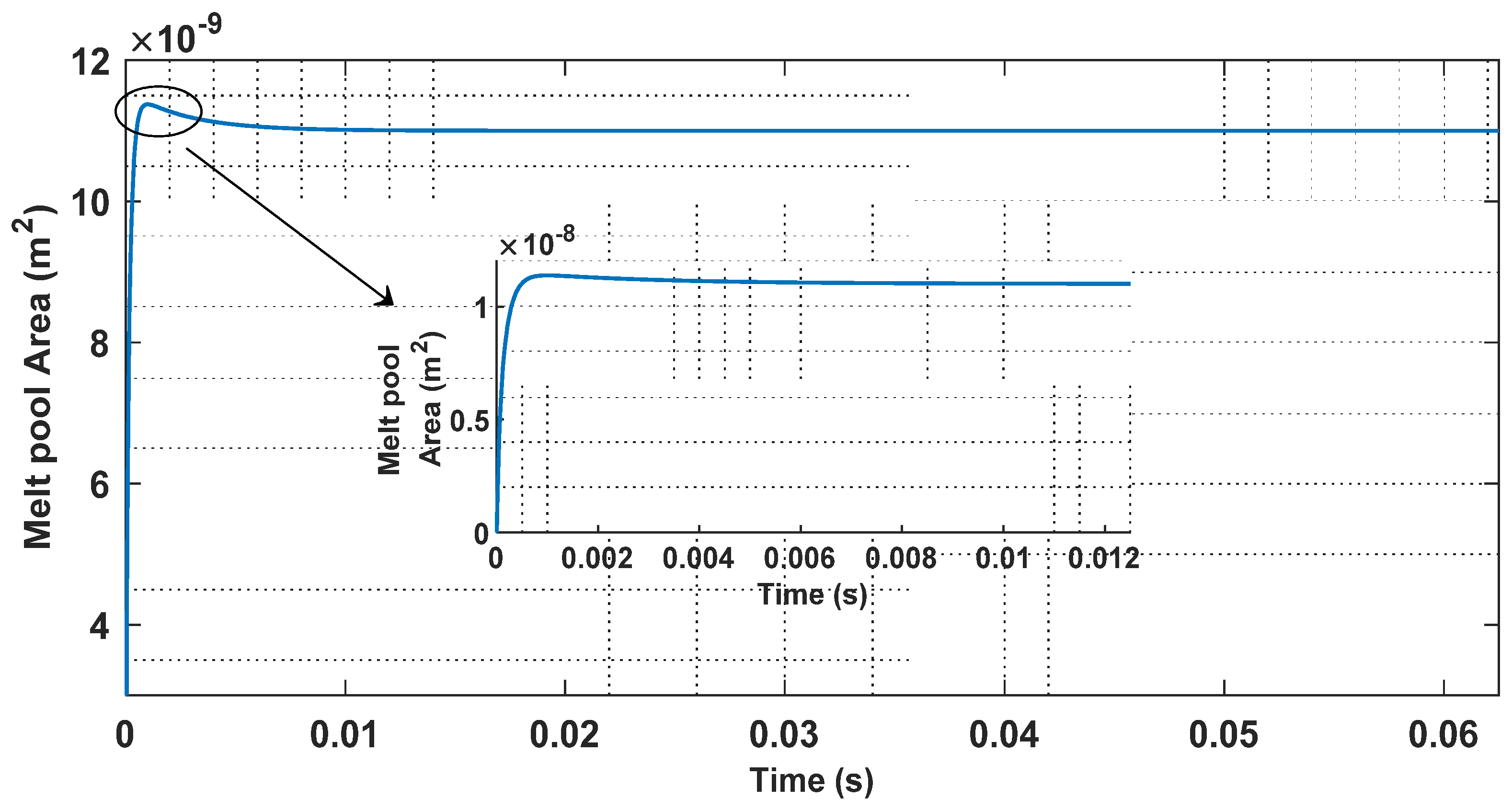
4.1. Open Loop Simulations Results

Open loop simulations were carried out to see the effect of the disturbing heat from previous tracks on temperature and the melt pool area using the developed model. The model predicted temperature as an initial temperature that causes this disturbing heat. Inconel 625 was chosen as a working material and its thermal properties are given in Table 1. The values of parameters “r” and “β” were taken from the literature [36]. The model was simulated for the laser scan of five tracks with a content laser power of Q = 250 W. The length of each track was 10 mm and the hatch spacing was 0.1 mm. The scan strategy was the same as shown in Figure 3. The scan speed was 800 mm/s and the skywriting time (the time to move from one track to another track) was not considered in the initial simulation. One of the limitations of the model was that thermal parameters such as thermal conductivity, density, and latent heat, which are in general temperature dependent are considered as constant. The effect of heat from previous tracks was modelled by the transient moving point heat source solution of Carslaw and Jaeger [29].
The initial temperature was considered as the ambient temperature of 292 K. The first track simulation results showed that the melt pool cross-section area reached a steady-state value of 1.1 × 10 8 m2. In the second and subsequent layers, the initial temperature gradually increased as shown in Figure 5. Due to this increased temperature, the melt pool cross-section area shows an increasing trend that gradually increased as shown in Figure 6. Thus, the presented model predicted the effect of the heat from previous tracks.

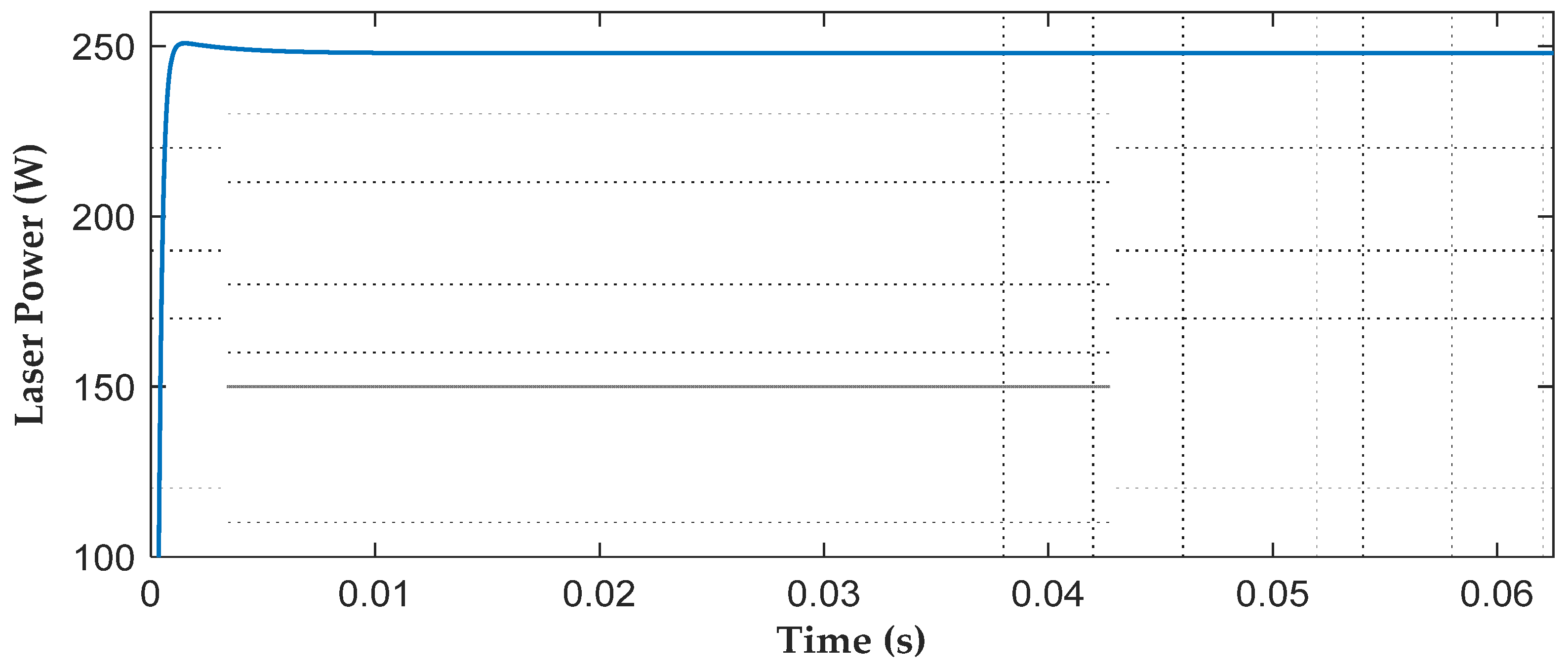
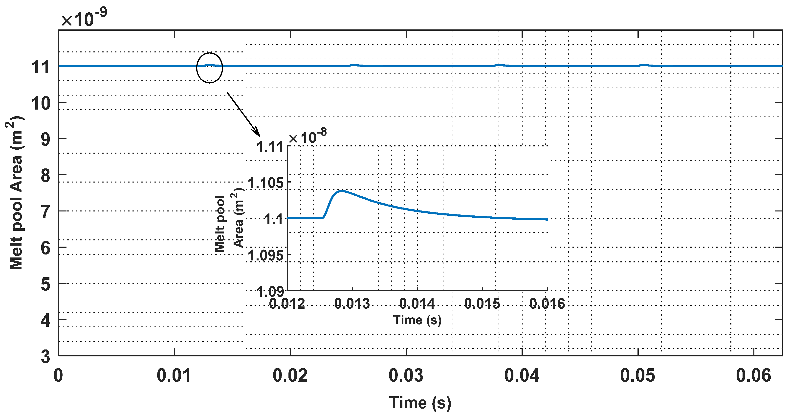
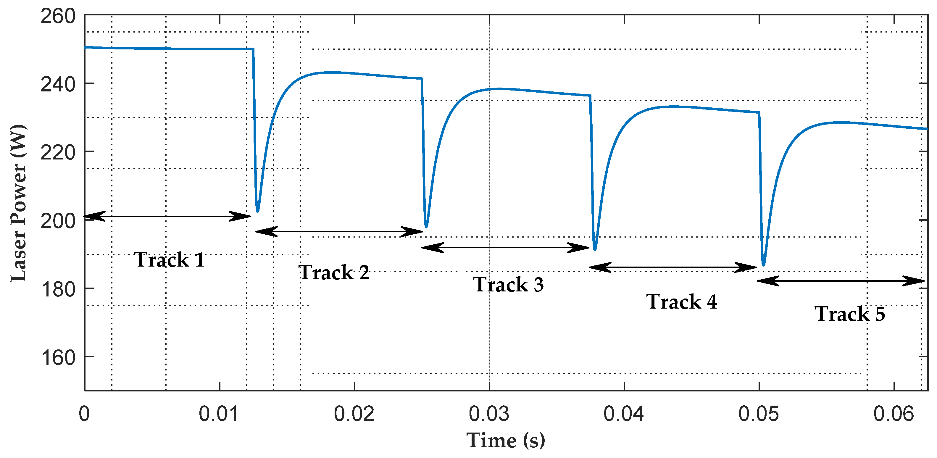
4.2. Closed Loop Simulations Results

The dynamic model of the melt pool cross-section area was nonlinear. The model was linearized at steady-state conditions. The linearized model was of the first order. Two cases were simulated and the PID control law was adopted for regulating the melt pool size by modulating the laser power.

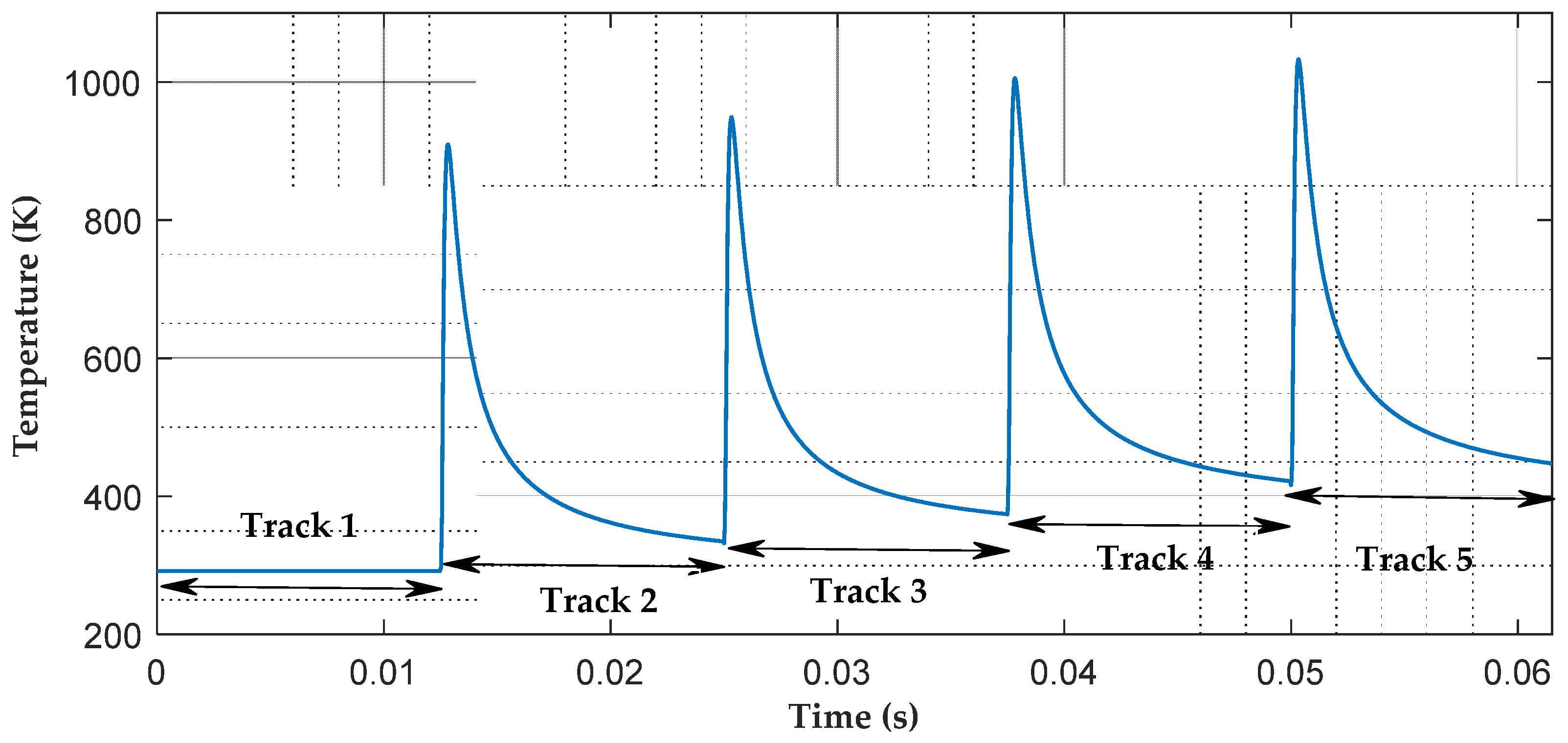
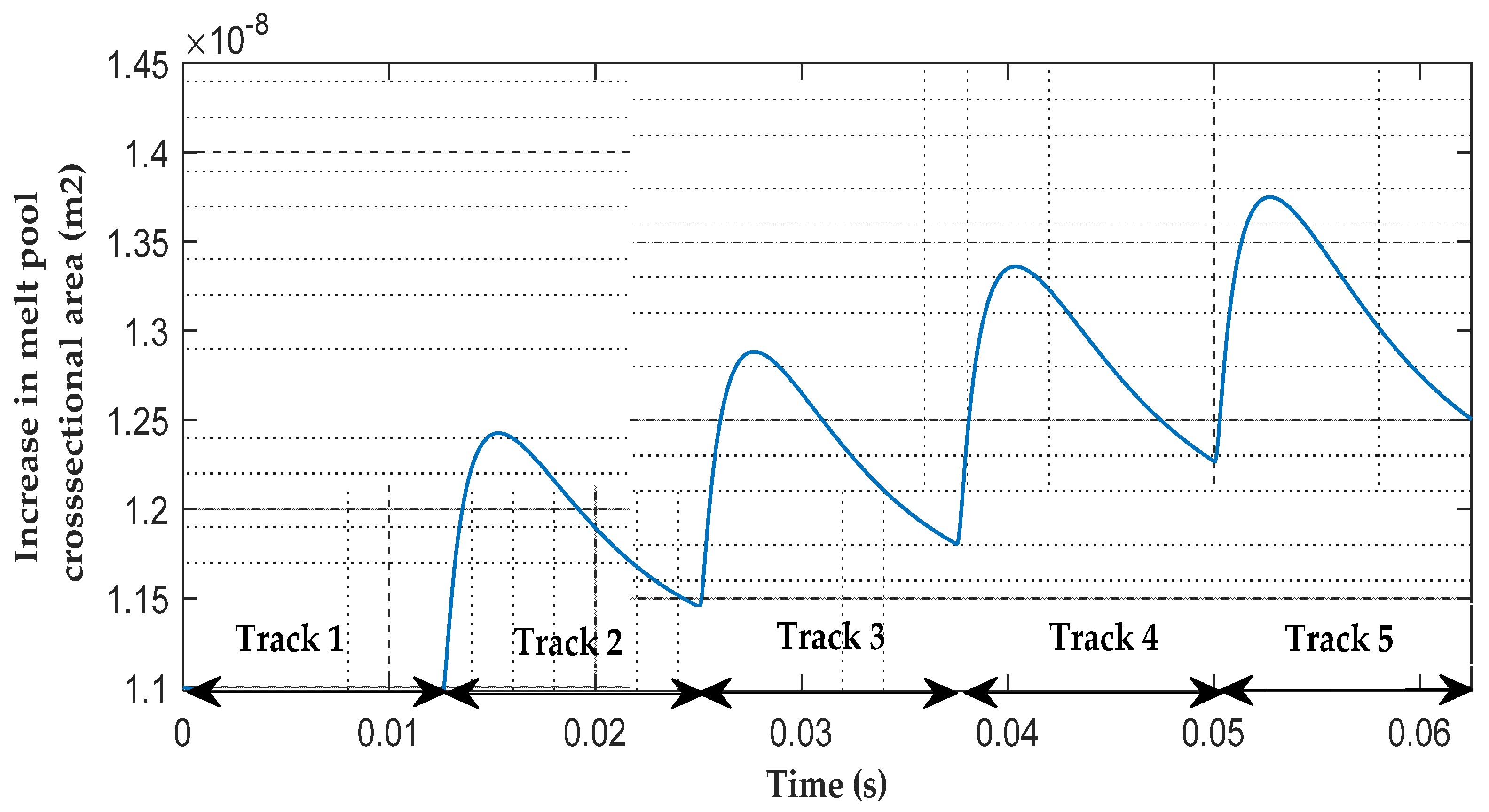
4.2.1. Case 1: Disturbance due to Environment Temperature, Tini = 290 K

In first case, the model was linearized by fixing the initial temperature at 290 K. This was the initial temperature of the first layer in the model. The linearized model transfer function was first order given by Equation (14).
A ( t ) P ( t ) = 3.935 × 10 8 1 + 11.01
Simulation results given in Figure 7 show that the laser power at 250 W maintained the steady-state melt pool area. The PID gains were tuned for a rise time of 3 µs. It also showed that the laser power remained constant once settled. This is because the input disturbance remains constant after a step change in it.

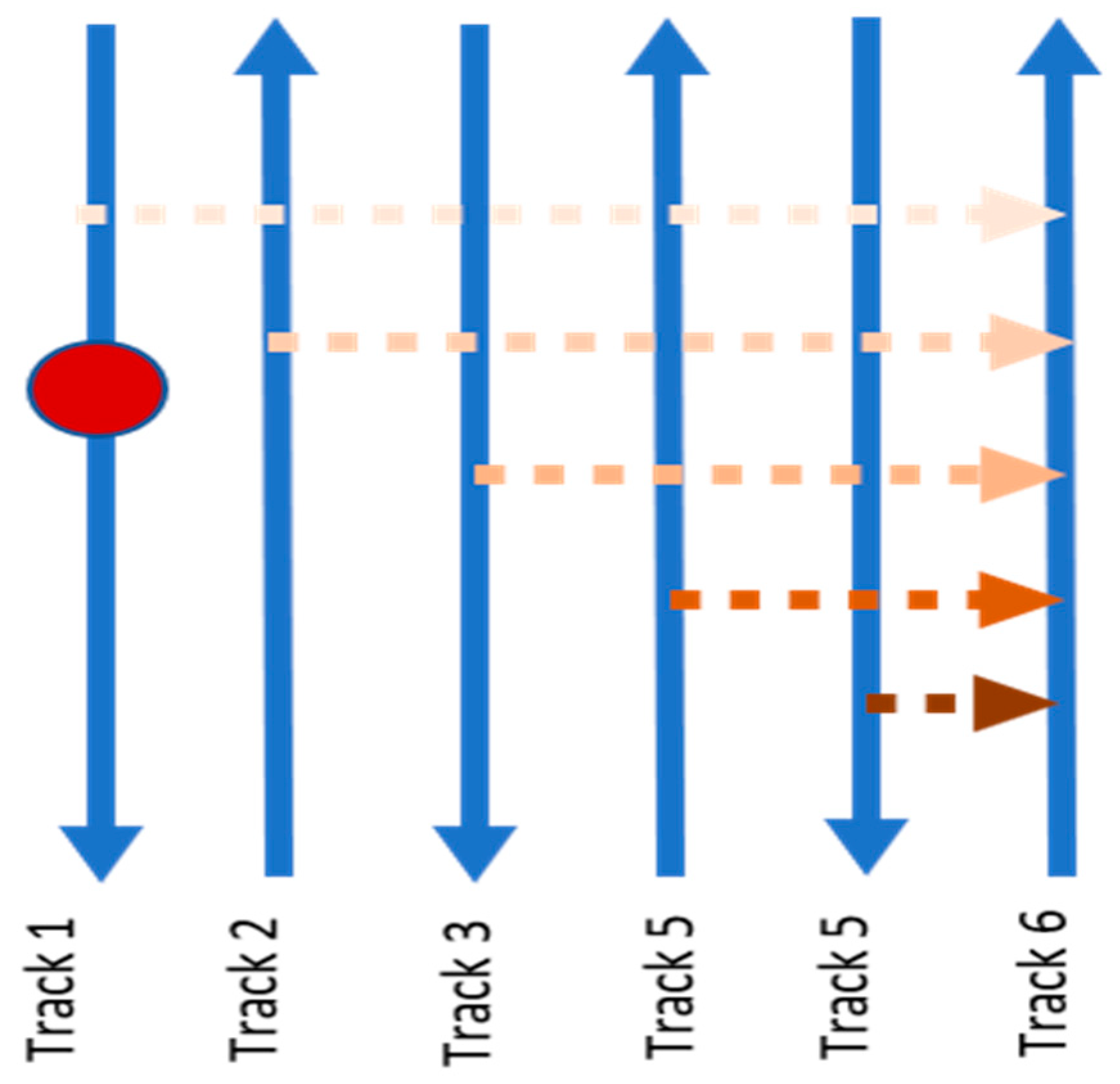
4.2.2. Case 2: Disturbance Due to Previous Tracks

In the second case, the initial temperature was varied using a transient moving heat source solution to model the effect of heat coming from previous tracks. The model was linearized at a steady-state value of the melt pool area and the corresponding first order transfer function is given by Equation (15).
A ( t ) P ( t ) = 3.935 × 10 8 1 + 13.23
In the control problem, the initial temperature was varied due to heat from previous tracks. This initial temperature was considered a disturbance and was used to calculate the change in melt pool area due to perturbed initial temperature. This disturbed area was added to the output area of the linearized model. The PID controller was used to minimize the effect of temperature disturbance. Results in Figure 8 show that the melt pool area was regulated to the reference value. During the laser scan of the first layer melt pool area, it reached a steady-state value of 1.1 × 10 8 m2 within 16 milliseconds. When the laser started the scanning of the second layer, the melt pool area was disturbed by energy from the previous track. This disturbance was rejected by the well tuned PID controller. In the third track laser scanning, the disturbance model incorporated the effect of energy from the first and second tracks. Thus, the disturbance effect increased but it was well regulated by the PID controller. The disturbance rejection in the second, third, fourth, and fifth tracks is shown in Figure 9.
The melt pool area was regulated by modulating the laser power. Figure 10 shows the variations of laser power beyond the first tracks to compensate for the area change due to extra heat from previous tracks. The laser power was decreased at the beginning of the second track and then gradually increased by the controller to account for the energy input from previous tracks. During the first track, the laser power remained constant at 250 W but varied along the second and further tracks. The results showed that the laser power was reduced by 10% in the fifth track but produced the same melt pool area as desired. The PID coefficients used for simulation of the disturbance rejection during regulation of the melt pool area are shown in Table 2.
The settling time of the melt pool area to the desired area, after disturbance, was fast as given in Table 2. The melt pool returned to a steady-state value before the laser had travelled 0.04 mm distance along the track of 10 mm. As a result, no key hole was made and gases were not trapped in the melt pool to cause porosity. Therefore, the PID controller performed well in maintaining the cross-sectional area and reduced the laser power as the laser moved ahead on tracks of a layer. This controller used the disturbing heat as source power and reduced the proportional amount of actual laser power. Hence, it kept the power within a critical value and reduced energy consumption too. This precluded key hole formation in the vicinity of the beam axis, which ultimately evaded the pore formation that was the main cause of the metal additive manufactured part failure. However, as expected, the performance of the PID controller was not robust since the controller is widely known to be not robust and quite vulnerable in adverse operating conditions. This is also due to the fact that PID controller gains are normally designed to be fixed for all conditions and thus are not optimized or adapted for different settings, environments, and conditions. Moreover, the mechanical properties of the SLM part are important and are related to uniform melt pool. If the melt pool is not uniform, it could result in defects such as pore formation and cracks. The presence of these defects reduces the strength and fatigue life of the part. Using a control strategy the defects were reduced and ultimately mechanical properties were improved. This may be proved by characterization of parts produced without feedback control and with feedback control in future.

5. Conclusions

In this work, a model-based regulation of melt pool geometry is presented. The model was based on the energy balance of a half ellipsoidal melt pool and disturbance energy from adjacent tracks of a layer of fusion bed of the SLM process. The model had a nonlinear dynamic and was linearized for the design of a control scheme. This model described the dynamics of the melt pool area as a function of initial temperature. The model was applied in two different scenarios. In the first case, the disturbance as an initial temperature was kept fixed as ambient temperature, and in the second case, the disturbance as initial temperature was considered changing over the tracks as the laser scanned the track. A disturbance model based on melt pool area variation due to heat from previous tracks was used to accommodate the energy coming from previous tracks. The PID-based closed loop feedback control system was designed to ensure uniform melt pool cross-sectional area in the presence of disturbance in selective laser melting by controlling the laser power. Simulation results have demonstrated the importance of PID control to regulate the melt pool area successfully. The results showed that the proposed PID controller stabilized the melt pool cross-sectional area during each track scan minimizing the error. This study indicates that feedback control is a good option in variable disturbance rejection. The proposed approach can be validated by in situ melt pool measurement or by comparing a single layer built with or without melt pool area regulation by altering laser power. The future work will be to enhance the model considering an enriched analytical solution as well as to design an advanced controller for disturbance rejection applying a nonlinear melt pool model and a further reduction in instability of the melt pool area.

Author Contributions

Conceptualization, S.Z.H. and Z.K.; methodology, S.Z.H. and Z.U.K.; software, S.Z.H.; validation, Z.K. and F.S.; formal analysis, Z.K.; investigation, S.Z.H. and Z.K.; re-sources, Z.K.; data curation, Z.K., S.R.S. and H.Z.U.R.; writing—original draft preparation, Z.K., S.Z.H. and M.F.S.; writing—review and editing, M.F.S., F.S., H.Y. and A.A.; visualization, Z.K. and M.F.S.; supervision, Z.K.; project administration, Z.K.; funding acquisition, M.F.S. and F.S. All authors have read and agreed to the published version of the manuscript.

Funding

This research received no external funding.

Institutional Review Board Statement

Not applicable.

Informed Consent Statement

Not applicable.

Data Availability Statement

Not applicable.

Acknowledgments

The authors acknowledge the support provided by Mechatronics Engineering Department of Air University, Islamabad and Khwaja Fareed University of Engineering and Information Technology (KFUEIT), Rahim Yar Khan, Pakistan.

Conflicts of Interest

The authors declare no conflict of interest.

Nomenclature

SymbolDescription
V ( t ) Volume of half ellipsoidal melt pool
A s Melt pool interface with the substrate
A G Melt pool interface with top free surface
rConstant melt pool width to depth ratio
βConstant melt pool length to width ratio

References

  1. Barroqueiro, B.; Andrade-Campos, A.; Valente, R.; Neto, V. Metal additive manufacturing cycle in aerospace industry: A comprehensive review. J. Manuf. Mater. Process. 2019, 3, 52. [Google Scholar] [CrossRef] [Green Version]
  2. Liu, Z.; He, B.; Lyu, T.; Zou, Y. A Review on Additive Manufacturing of Titanium Alloys for Aerospace Applications: Directed Energy Deposition and Beyond Ti-6Al-4V. JOM 2021, 73, 1804–1818. [Google Scholar] [CrossRef]
  3. Gupta, S.K.; Shahidsha, N.; Bahl, S.; Kedaria, D.; Singamneni, S.; Yarlagadda, P.K.D.V.; Suwas, S.; Chatterjee, K. Enhanced biomechanical performance of additively manufactured Ti-6Al-4V bone plates. J. Mech. Behav. Biomed. Mater. 2021, 119, 104552. [Google Scholar] [CrossRef]
  4. Jamshidi, P.; Aristizabal, M.; Kong, W.; Villapun, V.; Cox, S.C.; Grover, L.M.; Attallah, M.M. Selective Laser Melting of Ti-6Al-4V: The Impact of Post-processing on the Tensile, Fatigue and Biological Properties for Medical Implant Applications. Materials 2020, 13, 2813. [Google Scholar] [CrossRef]
  5. Singh, R.; Gupta, A.; Tripathi, O.; Srivastava, S.; Singh, B.; Awasthi, A.; Rajput, S.; Sonia, P.; Singhal, P.; Saxena, K.K. Powder bed fusion process in additive manufacturing: An overview. Mater. Today: Proc. 2020, 26, 3058–3070. [Google Scholar] [CrossRef]
  6. Yap, C.Y.; Chua, C.K.; Dong, Z.L.; Liu, Z.H.; Zhang, D.Q.; Loh, L.E.; Sing, S.L. Review of selective laser melting: Materials and applications. Appl. Phys. Rev. 2015, 2, 041101. [Google Scholar] [CrossRef]
  7. Bäßler, R. Additive Manufacturing of Metals–From Fundamental Technology to Rocket Nozzles, Medical Implants, and Custom Jewelry (Book Review); Wiley-VCH Verlag GmbH & Co. KgaA: Weinheim, Germany, 2018. [Google Scholar]
  8. Mani, M.; Lane, B.M.; Donmez, M.A.; Feng, S.C.; Moylan, S.P. A review on measurement science needs for real-time control of additive manufacturing metal powder bed fusion processes. Int. J. Prod. Res. 2017, 55, 1400–1418. [Google Scholar] [CrossRef] [Green Version]
  9. Zhang, B.; Li, Y.; Bai, Q. Defect formation mechanisms in selective laser melting: A review. Chin. J. Mech. Eng. 2017, 30, 515–527. [Google Scholar] [CrossRef] [Green Version]
  10. Malekipour, E.; El-Mounayri, H. Common defects and contributing parameters in powder bed fusion AM process and their classification for online monitoring and control: A review. Int. J. Adv. Manuf. Technol. 2018, 95, 527–550. [Google Scholar] [CrossRef]
  11. Patterson, A.E.; Messimer, S.L.; Farrington, P.A. Overhanging features and the SLM/DMLS residual stresses problem: Review and future research need. Technologies 2017, 5, 15. [Google Scholar] [CrossRef]
  12. Tapia, G.; Elwany, A. A review on process monitoring and control in metal-based additive manufacturing. J. Manuf. Sci. Eng. 2014, 136, 060801. [Google Scholar] [CrossRef]
  13. Vlasea, M.L.; Lane, B.; Lopez, F.; Mekhontsev, S.; Donmez, A. Development of powder bed fusion additive manufacturing test bed for enhanced real-time process control. In Proceedings of the International Solid Freeform Fabrication Symposium, Austin, TX, USA, 10–12 August 2015; pp. 13–15. [Google Scholar]
  14. Song, L.; Mazumder, J. Feedback control of melt pool temperature during laser cladding process. IEEE Trans. Control Syst. Technol. 2010, 19, 1349–1356. [Google Scholar] [CrossRef]
  15. Song, L.; Bagavath-Singh, V.; Dutta, B.; Mazumder, J. Control of melt pool temperature and deposition height during direct metal deposition process. Int. J. Adv. Manuf. Technol. 2012, 58, 247–256. [Google Scholar] [CrossRef]
  16. Wang, Q.; Li, J.; Gouge, M.; Nassar, A.R.; Reutzel, E.W. Physics-based multivariable modeling and feedback linearization control of melt-pool geometry and temperature in directed energy deposition. J. Manuf. Sci. Eng. 2017, 139, 021013. [Google Scholar] [CrossRef]
  17. Fathi, A.; Khajepour, A.; Toyserkani, E.; Durali, M. Clad height control in laser solid freeform fabrication using a feedforward PID controller. Int. J. Adv. Manuf. Technol. 2007, 35, 280–292. [Google Scholar] [CrossRef]
  18. Devesse, W.; De Baere, D.; Guillaume, P. Design of a model-based controller with temperature feedback for laser cladding. Phys. Procedia 2014, 56, 211–219. [Google Scholar] [CrossRef] [Green Version]
  19. Wang, Q.; Li, J.; Nassar, A.R.; Reutzel, E.W.; Mitchell, W.F. Model-Based Feedforward Control of Part Height in Directed Energy Deposition. Materials 2021, 14, 337. [Google Scholar] [CrossRef]
  20. Wang, D.; Chen, X. Synthesis and Analysis of Multirate Repetitive Control for Fractional-Order Periodic Disturbance Rejection in Powder Bed Fusion. In Proceedings of the International Symposium on Flexible Automation, Kanazawa, Japan, 15–19 July 2018; pp. 30–38. [Google Scholar]
  21. Shkoruta, A.; Caynoski, W.; Mishra, S.; Rock, S. Iterative learning control for power profile shaping in selective laser melting. In Proceedings of the 2019 IEEE 15th International Conference on Automation Science and Engineering (CASE), Vancouver, BC, Canada, 22–26 August 2019; pp. 655–660. [Google Scholar]
  22. Wang, Q.; Michaleris, P.P.; Nassar, A.R.; Irwin, J.E.; Ren, Y.; Stutzman, C.B. Model-based feedforward control of laser powder bed fusion additive manufacturing. Addit. Manuf. 2020, 31, 100985. [Google Scholar] [CrossRef]
  23. Spector, M.J.; Guo, Y.; Roy, S.; Bloomfield, M.O.; Maniatty, A.; Mishra, S. Passivity-based iterative learning control design for selective laser melting. In Proceedings of the 2018 Annual American Control Conference (ACC), Milwaukee, WI, USA, 27–29 June 2018; pp. 5618–5625. [Google Scholar]
  24. Craeghs, T.; Bechmann, F.; Berumen, S.; Kruth, J.-P. Feedback control of Layerwise Laser Melting using optical sensors. Phys. Procedia 2010, 5, 505–514. [Google Scholar] [CrossRef] [Green Version]
  25. Renken, V.; Albinger, S.; Goch, G.; Neef, A.; Emmelmann, C. Development of an adaptive, self-learning control concept for an additive manufacturing process. CIRP J. Manuf. Sci. Technol. 2017, 19, 57–61. [Google Scholar] [CrossRef]
  26. Renken, V.; Lübbert, L.; Blom, H.; von Freyberg, A.; Fischer, A. Model assisted closed-loop control strategy for selective laser melting. Procedia CIRP 2018, 74, 659–663. [Google Scholar] [CrossRef]
  27. Renken, V.; von Freyberg, A.; Schünemann, K.; Pastors, F.; Fischer, A. In-process closed-loop control for stabilising the melt pool temperature in selective laser melting. Prog. Addit. Manuf. 2019, 4, 411–421. [Google Scholar] [CrossRef]
  28. Doumanidis, C.; Kwak, Y.-M. Geometry modeling and control by infrared and laser sensing in thermal manufacturing with material deposition. J. Manuf. Sci. Eng. 2001, 123, 45–52. [Google Scholar] [CrossRef]
  29. Carslaw, H.; Jaeger, J. Heat Conduction in Solids; Oxford University Press: Oxford, UK, 1959. [Google Scholar]
  30. Sammons, P.M.; Gegel, M.L.; Bristow, D.A.; Landers, R.G. Repetitive process control of additive manufacturing with application to laser metal deposition. IEEE Trans. Control Syst. Technol. 2018, 27, 566–575. [Google Scholar] [CrossRef]
  31. Wang, Q.; Li, J.; Nassar, A.R.; Reutzel, E.W.; Mitchell, W. Build height control in directed energy deposition using a model-based feed-forward controller. In Proceedings of the ASME 2018 Dynamic Systems and Control Conference, Atlanta, GA, USA, 30 September–3 October 2018. [Google Scholar]
  32. Dillkötter, D.; Mönnigmann, M. Design of a model based feedforward controller for additive manufacturing by laser metal deposition. In Proceedings of the 2019 18th European Control Conference (ECC), Naples, Italy, 25–28 June 2019; pp. 3842–3847. [Google Scholar]
  33. Egan, D.S.; Jones, K.; Dowling, D.P. Selective laser melting of Ti-6Al-4V: Comparing μCT with in-situ process monitoring data. CIRP J. Manuf. Sci. Technol. 2020, 31, 91–98. [Google Scholar] [CrossRef]
  34. Promoppatum, P.; Yao, S.-C. Influence of scanning length and energy input on residual stress reduction in metal additive manufacturing: Numerical and experimental studies. J. Manuf. Process. 2020, 49, 247–259. [Google Scholar] [CrossRef]
  35. Lu, X.; Chiumenti, M.; Cervera, M.; Tan, H.; Lin, X.; Wang, S. Warpage Analysis and Control of Thin-Walled Structures Manufactured by Laser Powder Bed Fusion. Metals 2021, 11, 686. [Google Scholar] [CrossRef]
  36. Wang, Q. A control-oriented model for melt-pool volume in laser powder bed fusion additive manufacturing. In Proceedings of the Dynamic Systems and Control Conference, Park City, UT, USA, 8–11 October 2019; p. V001T010A002. [Google Scholar]
Figure 1. SLM process parameters: laser power, scanning speed, hatch spacing, and layer thickness.
Processes 09 01547 g001
Figure 2. Melt pool (Lateral view) describing the layout of dimensional parameters and areas.
Processes 09 01547 g002
Figure 3. A description of the intralayer disturbance model due to the previous track’s heat. The heat coming from previous tracks increases the initial temperature of the current track being scanned.
Processes 09 01547 g003
Figure 4. Schematics of the laser power controller architecture.
Processes 09 01547 g004
Figure 5. Melt pool model’s initial temperature variation along each track.
Processes 09 01547 g005
Figure 6. Melt pool area variation along each track due to heat coming from previously scanned tracks.
Processes 09 01547 g006
Figure 7. Laser input power for all tracks for case 1. i = 290 is considered as a disturbance.
Processes 09 01547 g007
Figure 8. Melt pool area regulated by PID control for case 1, Tini = 290 is considered as a disturbance.
Processes 09 01547 g008
Figure 9. Melt pool cross-section area is regulated by PID control scheme for the five tracks considered in the simulation.
Processes 09 01547 g009
Figure 10. Laser input power variation across each track. Laser power decreased at the start of each scan to keep the melt pool area constant.
Processes 09 01547 g010
Table 1. Material properties of Inconel 625.
ParameterValue
Density: ρ8840 kg/m3
Thermal Conductivity: k9.8 W/m·K
Thermal Diffusivity: a30,914 mm2/s
Melting Temperature: Tm1568 K
Specific Heat of Solid Inconel: Cp550 J/kg·K
Specific Heat of Molten Inconel: Cp680 J/kg·K
Solidus Temperature: Ts1290 K
liquidus Temperature: Ts1350 K
Latent Heat: Hf22,700 J/kg
Absorption: η40%
Convection Coefficient: αs2 × 105 W/m2·K
Heat Transfer Coefficient: αG20 W/m2·K
Temperature Ratio: μ0.2
Melt Pool Width to Depth Ratio: r1.75
Melt Pool Length to Width Ratio: β10
Table 2. PID parameters.
CaseSettling Time (s)Rise Time (s)KpKiKd
Tini = 0 3.62   ×   10 4 2.92   ×   10 3 1.13   ×   10 10 9.23   ×   10 13 5.31   ×   10 5
Tini = 290 2.96   ×   10 3 2.57   ×   10 3 1.99   ×   10 11 7.91   ×   10 13 4.63   ×   10 6
Tini by Disturbance Model 5.05   ×   10 5 9.65   ×   10 5 9.99   ×   10 11 9.99   ×   10 11 9.91   ×   10 8
Publisher’s Note: MDPI stays neutral with regard to jurisdictional claims in published maps and institutional affiliations.

