Article

Conductive Compartmented Capsules Encapsulating a Bitumen Rejuvenator

1
Centre for Research in Engineering Surface Technology (CREST), Technological University Dublin, D08CKP1 Dublin, Ireland
2
School of Civil Engineering, University College Dublin, D04K3H4 Dublin, Ireland
3
Civil Engineering and Geosciences, Delft University of Technology, 2628 CN Delft, The Netherlands
4
Polytechnic Faculty, University of Zenica, Fakultetska 1, 72000 Zenica, Bosnia and Herzegovina
*
Author to whom correspondence should be addressed.
Processes 2021, 9(8), 1361; https://doi.org/10.3390/pr9081361
Submission received: 22 June 2021 / Revised: 27 July 2021 / Accepted: 28 July 2021 / Published: 3 August 2021
(This article belongs to the Section Materials Processes)

Abstract

:
This paper explores the potential use of conductive alginate capsules encapsulating a bitumen rejuvenator as a new extrinsic self-healing asphalt method. The capsules combine two existing self-healing asphalt technologies: (1) rejuvenator encapsulation and (2) induction heating to create a self-healing system that will provide rapid and effective asphalt pavement repair. The work presents a proof of concept for the encapsulation process, which involves embedding the capsules into the bitumen mortar mixture and the survival rate of the capsules in the asphalt mixture. A drip capsule production process was adopted and scaled up to the production of 20l wet capsules at rate of 0.22 l/min. To prove the effectiveness and its ability to survive asphalt production process, the capsules were prepared and subjected to thermogravimetric analysis (TGA) and uniaxial compression Test (UCT). The test results demonstrated that the capsules had suitable thermal characteristics and mechanical strength to survive the asphalt mixing and compaction process. Scanning electron microscopy (SEM) was employed to investigate physiological properties, such as rejuvenator (oil) and iron particle distribution, within the capsules. The electrical resistance tests proved that the capsules were capable of conducting electrical current. The capsules were also tested for their conductive properties in order to determine whether they are capable of conducting and distributing the heat once subjected to induction heating. The results showed that capsules containing higher amounts of iron (alginate/iron powder in a ratio of 20:80 by weight) can efficiently conduct and distribute heat. To prove its success as an asphalt healing system, conductive alginate capsules encapsulating a bitumen rejuvenator were embedded in a bitumen mortar mix. The samples where then subjected to local damaging and healing events, and the degree of healing was quantified. The research findings indicate that conductive alginate capsules encapsulating a bitumen rejuvenator present a promising new approach for the development of an extrinsic self-healing asphalt pavement systems.

1. Introduction

The emergence of self-healing technologies for asphalt pavements signified a turning point in the 250-year evolution of the road [1]. For the past two decades, asphalt self-healing technology has been gaining attention amongst bituminous (asphalt) researchers, engineers, industry, and road owners [2,3]. The RILEM (The International Union of Laboratories and Experts in Construction Materials, Systems and Structures) Technical Committee TC 278-CHA (Crack-Healing of Asphalt Pavement Materials) have classified the asphalt crack healing terminology [4] into the following two categories:
(i) Intrinsic (self-)healing: aspect of the asphalt self-healing behavior that is inherent to the material used, and
(ii) Extrinsic (self-)healing: aspect of the asphalt self-healing behavior that can be attributed to an added phase or action that is specifically used to improve self-healing capabilities, to trigger crack-healing or prevent crack propagation.
The idea of extrinsic self-healing for asphalt pavements (roads) stems from the concept of the “forever open road”, motivated by the need to avoid the traffic disruption caused by road maintenance activities on busy roads. A new challenge arising for the road industry is how to ensure the safety of road construction workers during the pandemic (safety from COVID-19 and also safety from traffic), and how will social distancing be possible for road construction/maintenance crews where repair crews are exposed to vehicle, cyclist, and pedestrian traffic [5]. In the UK, 175 crashes per month are caused by drivers driving into roadwork sites [6]. The USA Centre for Construction Research and Training (CPWR) reported 1230 fatalities and 324,000 work zone injuries of road construction workers between 2009–2018 [7]. These figures show that current road maintenance processes necessitate a high level of risk and danger for road maintenance workers. In addition, extrinsic self-healing asphalt technology has the potential to reduce the environmental impact of road construction. The environmental benefit of the quality and service life extension of roads is an estimated reduction of 30% in energy consumption and CO2 emissions over the lifetime of the road [8]. Extrinsic self-healing asphalt technology has potential to address the technical, economic, environmental, and societal challenges faced by roads industry, road owners, and society.
To date, researchers have tested the following three self-healing methods for asphalt pavements [2]:
(i) Induction heating: a method that involves adding electrically conductive fillers (steel fibres and steel wool) to the asphalt mix and initiating healing by sending an alternating current through the coil. When the conductive asphalt specimen is placed beneath the coil for 3–5 min, the electromagnetic field induces currents flowing along the conductive loops within the asphalt formed by steel fibres [9]. The current causes the conductive particles, such as steel fibres or iron powder, within the asphalt to heat, which in turn softens the bitumen, allowing it to flow and seal the cracks and repairing the damage [2,10,11,12].
(ii) Microwave heating: creates high energy wavelengths that react with the conductive particles in the asphalt. Similar to induction heating, microwave heating causes the conductive particles, e.g., steel fibres, embedded in the bitumen mix to heat up, which then heats the aged bitumen and softens it, allowing it to flow and repair the micro crack damage. Laboratory studies have shown this method can repair test specimen damage within 3 min [13,14,15] of heating. The microwave method requires less conductive fibres to achieve the required temperature needed to heal the damage.
(iii) Rejuvenation: a method that involves adding an encapsulated healing agent (rejuvenator) into the asphalt mix to restore the original bitumen properties. When micro-cracks form within the pavement, they encounter a capsule. The fracture energy at the tip of the propagating crack opens the capsule, releasing the healing agent, which then diffuses within the bitumen to seal the crack [16,17,18]. The rejuvenator encapsulation approach represents a more favourable method of asphalt self-healing, as it enables the aged bitumen to return it to its original chemical, physical, and mechanical properties. However, there are limitations with this method of self-healing because the healing rate is slow [19,20].
Researchers have demonstrated that the induction and microwave heating methods are more efficient methods of healing asphalt damage (3 to 5 min) [3,20]. However, a challenge with these two methods is that the induction heating process ages the bitumen, causing binder brittleness and the premature failure of the asphalt. In response to this challenge, Xu et al. [20] developed a self-healing asphalt system that combined induction heating and rejuvenation. In this process, induction heating is used to repair the asphalt damage (and the cracks), while rejuvenation is used to replenish the aged asphalt binder (bitumen). Xu et al. also showed that a combined healing system improves the healing efficiency, allowing for rapid damage repair and a simultaneous rejuvenation of the aged asphalt mix. However, a challenge in this approach is that the bituminous mix has to be adjusted to accommodate for the inclusion of both capsules and steel fibres. A solution to this problem lies in combining the induction and rejuvenation into one product. Most recently Wan et al. [15] developed Calcium alginate/nano-Fe3O4 composite capsules for controlled rejuvenator oil release using microwave heating.
This paper presents development of a novel extrinsic self-healing asphalt technology, conductive alginate capsules encapsulating a bitumen rejuvenator (oil), which reinforces the asphalt pavement by improving its tensile and compressive strength and enhancing its autonomous healing properties via induction heating. The concept combines two existing self-healing asphalt technologies, (i) rejuvenator encapsulation and (ii) induction heating to create a self-healing system that will provide rapid and effective asphalt pavement repair. The study focuses on the optimisation of the capsules mix by evaluating the capsules’ physical and mechanical properties, and by conducting tests such as viscosity, conductivity, and compression strength tests. To prove the concept, conductive alginate capsules encapsulating a bitumen rejuvenator were manufactured and embedded in a bitumen and bitumen mortar mix. The bitumen and bitumen mortar test samples, with varying amounts of capsules, were subjected to a testing programme that consisted of indirect tensile strength (ITS) test loading and healing events. The degree of self-healing initiated in the test samples was then measured and quantified. This research demonstrates the first promising results using a conductive alginate capsule encapsulating a bitumen rejuvenator to promote asphalt healing, and paves the way for further development and future research in this area.

2. Materials and Methods

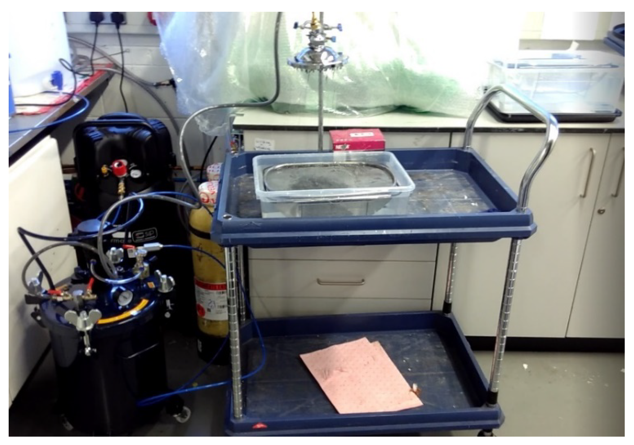
2.1. Conductive Alginate Capsules Encapsulating Bitumen Rejuvenator

All of the chemicals used in the conductive alginate capsule encapsulating rejuvenator production process were purchased from Merck Group, Sigma Aldrich, Ireland, except for the rejuvenator (vegetable oil), which was purchased from the local supermarket.
The conductive alginate capsules encapsulating a bitumen rejuvenator were prepared using a drop process [17,21] from an emulsion of rejuvenator suspended in a water solution of sodium alginate. For this, a 6 wt.% solution of sodium alginate in de-ionized water was prepared. At the same time, a 2.5 wt.% poly(ethylene-alt-maleic-anhydride) (PEMA) polymeric surfactant solution was prepared by dissolving the copolymer in water at 70 °C and mixing it for 60 min. After the PEMA was dissolved in the water, it was allowed to cool to room temperature (20 ± 2 °C), and was combined with the rejuvenator. For this study, a vegetable oil of 0.9 g/cm3 density at a room temperature (20 ± 3 °C) was used, forming a bitumen healing agent solution, in a PEMA/rejuvenator at a ratio of 1/1.5 proportion by weight. The sodium alginate solution was mixed with iron powder (40 μm particle size), at 700 rpm for 1 h to allow for uniform iron particle dispersal within the alginate mix. Five different alginate (Alg)/iron powder (Fe) mix ratios were prepared in proportions of the weight of dry constituents ratios of 100:0, 70:30, 50:50, 30:70, and 20:80. After the sodium alginate and iron solution was fully mixed, the PEMA and rejuvenator (oil) solution was added to the alginate–iron powder solution mix with a ratio of 70% rejuvenator to 30% sodium alginate [1]. The full capsule solution was mixed at 700 rpm for 20 min. For small capsule volume solution mixtures, it was sufficient to mix the constituents for 2 min at 200 rpm [1,17]. As the capsule production was scaled up from 20 mL to 20 L, it was necessary to increase the mixing time and rate in order to allow for suitable oil and iron particle distribution throughout the capsule solution.
The capsules were produced using a drip production process using a 20 L capacity pressurised system. Figure 1 illustrates the capsule production system. The pressurised cylinder was equipped with a pneumatic stirrer, which was used to agitate the solution within the pressurised cylinder during the capsule production process in order to prevent iron segregation at the bottom of the cylinder. The stirring rate was controlled during the process via an air pressure valve. The stirring rate during the production process was kept at 200 rpm. A shower head with 61 capillary openings of 1 mm diameter was used as the drip system. The production rate was 0.222 L/min. A 10l bath with an inserted sieve containing a 0.45 M solution of CaCl2·6H2O was used for the capsule coagulation. After production, the capsules were dried in the oven for 12 h at 40 °C. Figure 2 shows an image of a dry conductive alginate capsule encapsulating bitumen rejuvenator (oil).

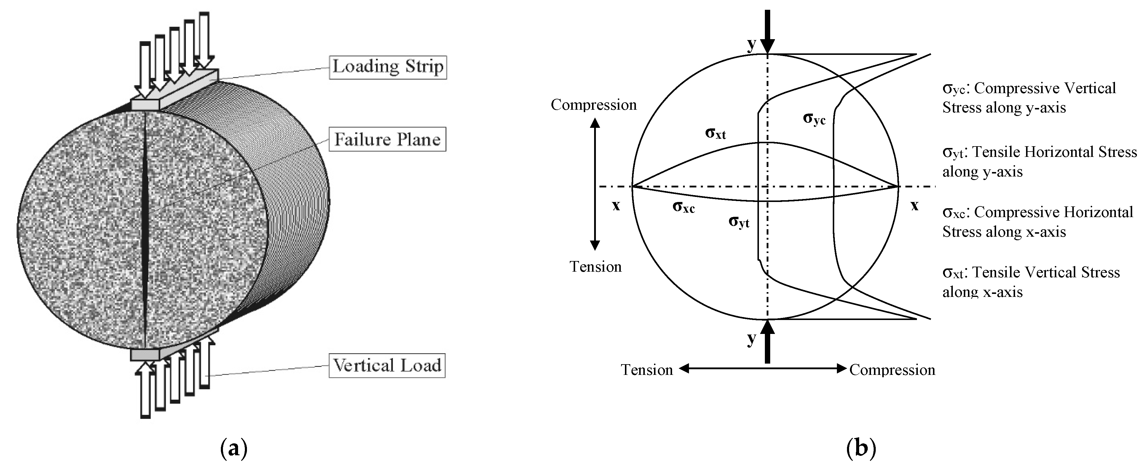
2.2. Bitumen and Mortar ITS

The bitumen used in the preparation of the indirect tensile strength (ITS) test specimens was 70/100 Pen bitumen supplied by Lagan Materials Ltd. The bitumen and mortar ITS test specimens were prepared using a Struers FixiForm non-stick mould with dimensions of a depth max (h) of 24 mm and diameter (d) of 30 mm (the mould is shown in Figure 3a). For this study, the diameter specimen height ratio was 2:1 (29 mm(d):14.5 mm(h)). The bitumen and capsules were preheated to 160 °C and then mixed together, and finally, the mixture was poured into the mould and left to cool down to room temperature (20 ± 3 °C) for 24 h. Table 1 summarises the test specimen constituent weight for both the bitumen and mortar test specimens. Figure 3 shows the mould, a bitumen test specimen, and ITS test set up. For the induction healing process, a cylindrical (ring) coil was used (see Figure 3b) with a 100 mm diameter and 50 mm height. The mould with the test specimen was placed in the centre of the ring, allowing for even induction heating throughout the test specimen. A Zwick Roell ZwickiLine Z5.0 TN for a Flexible Low-Force Testing machine was used to carry out the ITS test. The tests were carried out at a loading rate of 0.1 mm/s and test temperature of 20 °C. The bitumen test specimens were very difficult to test at room temperature, as they were very soft and would deform rather than crack. Attempts were made to precondition the test specimens in a fridge at 5 °C and freezer at −19 °C. Unfortunately, as testing was carried out without a temperature-controlled chamber, the specimens would heat up to room temperature very quickly. For this reason, the test specimens were submerged in liquid nitrogen for 10 s before testing. The bitumen test specimens containing 5% and 7% capsules completely deformed when extracted from the mould. As a result, only test specimens containing 10% and 20% capsules were successfully tested.
The ITS test was conducted by applying a vertical compressive strip load to a cylindrical specimen. The load was distributed over the thickness of the specimen through two loading strips at the top and bottom, as indicated in Figure 4a. The combination of specimen geometry and boundary conditions induced tensile and compressive stress along both the vertical and horizontal diameters, as indicated in Figure 4b. The tensile stresses, which developed perpendicular to the direction of the load, were of a relatively constant value over a large portion of the vertical diameter. This would be expected to cause failure of the specimen by splitting along the vertical diameter, as indicated in Figure 4a.
The critical stresses and strains within the indirect tensile specimen were computed using an analytical formulation based on linear elastic theory. This theory assumes that the material is homogenous and isotropic, that it only experiences plane stress conditions, and that the loading strips are simplified to line loads. Linear elastic stress analysis solutions are given by Timoshenko [22]. On the vertical diameter, the maximum and average stresses in the x and y direction are as follows:
σ x ( max ) = 2 P π d t
σ y ( max ) = 6 P π d t
σ x ( a v g ) = 0.27 P d t
σ y ( a v g ) = P d t
where:
  • σx = maximum or average stress in the x direction on the vertical plane (Pa),
  • σy = maximum or average stress in the y direction on the vertical plane (Pa),
  • P = applied vertical load (N),
  • d  = diameter of the specimen (mm),
  • t  = thickness of the specimen (mm).

2.3. Capsule Composite Characterisation

2.3.1. Viscosity

The A&D Vibroviscometer SV-10 was used to measure viscosity of the capsule alginate solutions. Viscosity values for solutions containing varying alginate/iron powder ratios (100:0; 70:30; 50:50; 30:70, and 20:80) were measured. The solution containing alginate and rejuvenating oil only, without iron, (Alg 100: Fe 0), was used as the control solution.

2.3.2. Relative Density

Following the procedure described in EN 162:2013, a beaker with a 50 mL volume was filled capsules until fully packed. Then, the mass of the capsules in the 50 mL beaker was measured. One representative sample for each capsule mix was used to determine the apparent relative density of each capsule mix. The relative density was determined as follows:
ρ 0 = m V 0
where:
  • ρ0 = relative density (g/cm3)
  • m = total mass of the capsules (g)
  • V0 = volume (cm3)

2.3.3. Scanning Electron Microscope (ESEM)

Scanning electron microscopy (SEM) was used to evaluate the morphology of the rejuvenator compartments within the sodium alginate fibres. For this purpose, a Hitachi SU-70 FESEM system was employed. A low accelerating voltage of 2 kV and a beam current of less than 1 nA were used to limit the electron beam damage on the heat sensitive polymeric capsules.

2.3.4. Thermogravimetric Analysis (TGA)

The thermal stability characterization of the conductive alginate capsule encapsulating a bitumen rejuvenator (oil) was performed using a Shimadzu DTG-60 Simultaneous DTA-TG system, at a scanning rate of 6.5 °C/min, under a nitrogen gas (N2) at a flow of 50 mL/min.

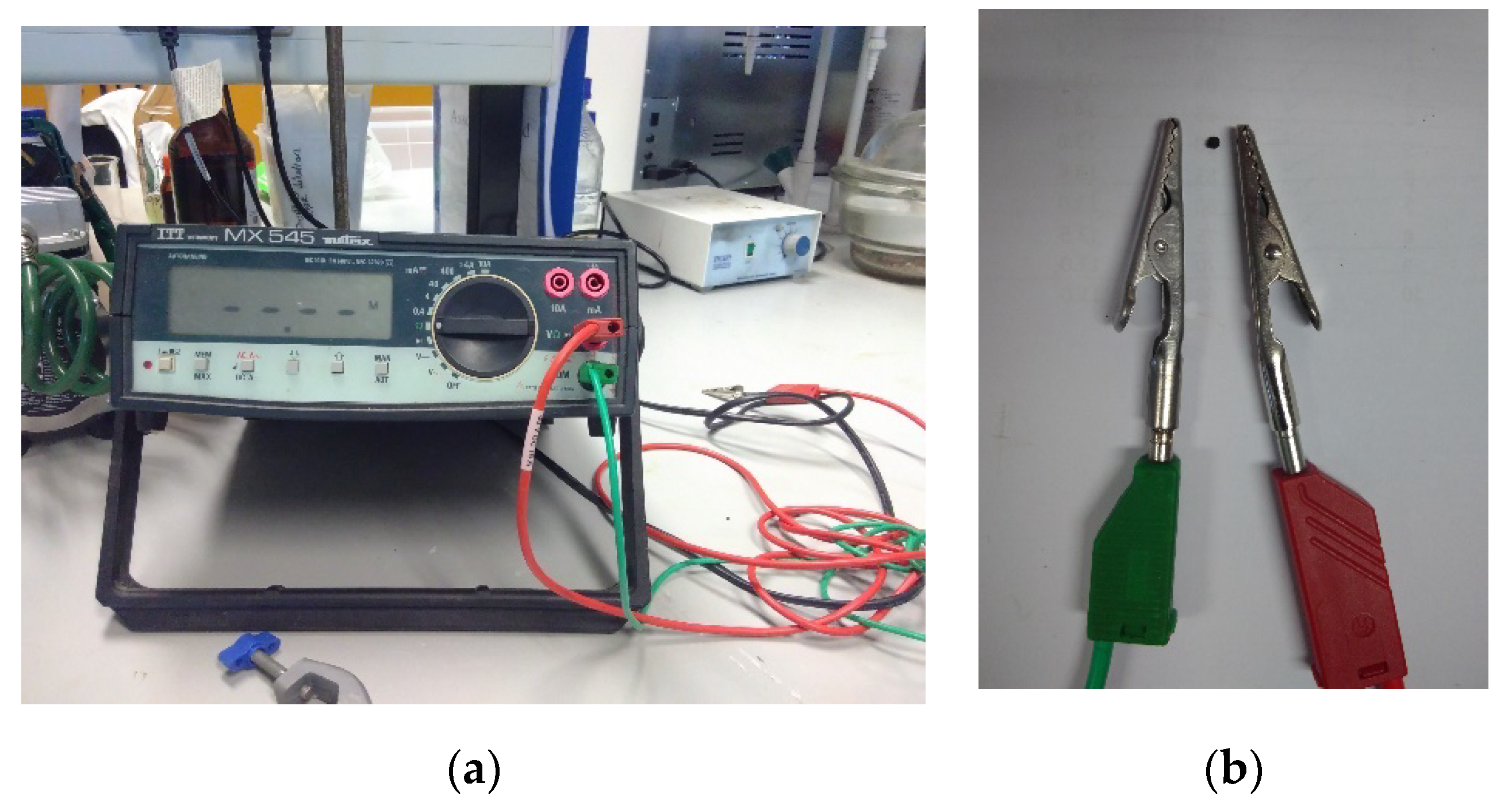
2.3.5. Electrical Resistivity

The capsule electrical resistivity was measured using an ITT Matrix MX 545 digital multimeter. The capsule electrical resistivity was measured by placing the conductivity pins on the opposite sides of the capsule. Figure 5 shows the test apparatus set up.

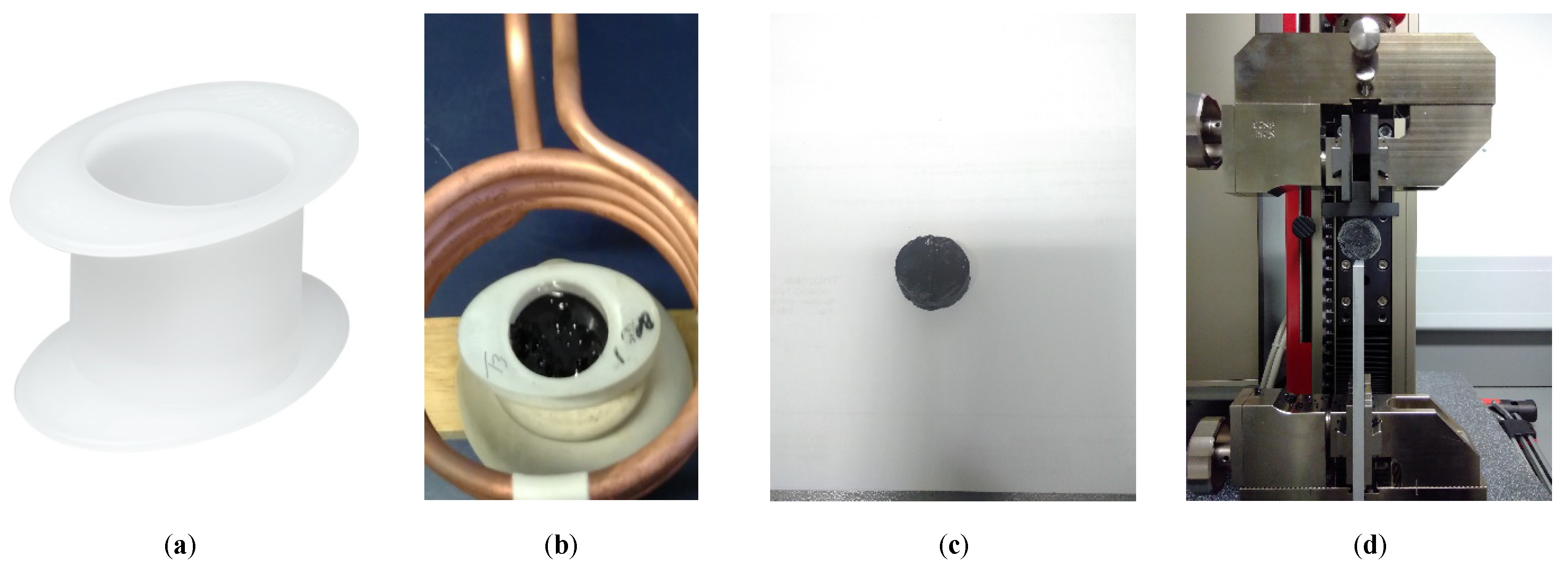
2.3.6. Uniaxial (Compression) Strength Test

A Zwick Roell ZwickiLine Z5.0 TN for Flexible Low-Force Testing machine was used to carry out the ITS test, Figure 3d shows the ITS system set up. Tests were carried out at a loading rate of 0.1 mm/s and test temperature of 20 °C. The effect of (a) temperature (b) humidity, (c) moisture, and (d) moisture and salt (brine) on the capsule strength was measured. The influence of temperature on the capsule strength was evaluated by placing capsules in the desired temperature for 3 h, and then left to condition for 1 h at room temperature (20 ± 2 °C) prior to testing. The conditioning temperatures were −19 °C, 6 °C, 20 °C, 40 °C, 80 °C, 120 °C, 160 °C, and 200 °C.
The effect of moisture on the capsule mechanical properties was carried out by placing a capsule in a dish with a salt water solution (100 g of water and 36 g of sodium chloride [23]). The capsules with a water/salt solution were sealed and left for 14 days to condition. The water/salt solution created a humid environment of 75% humidity. Finally, the effect of salt on the mechanical strength of the capsules was tested by submerging the capsules in brine (salty water) for 72 h.
In order to calculate the capsule compression strength, the Hertz Theory of elastic contact between a steel plate and elastic sphere was adopted [24]. The maximum compressive stress was expected at the contact region between the loading plate and tip of the capsule. As such, contact pressure (Pc) was adopted here as a capsule strength indicator. Using the Hertz formulae [24], contact width “a”, necessary for all calculations, is given by the following:
a = 3 P R e q 4 E e q 3
where
  • a  = contact area (m)
  • P = Load (N)
  • Req = Equivalent Radius (m);
R e q = ( 1 R 1 + 1 R 2 ) 1  
for this study, as the loading plate face is flat R2, therefore R2 = ∞ so 1/R2 = 0.
Eeq  = equivalent modulus of elasticity (Pa);
E e q = ( 1 ν 1 2 E 1 + 1 ν 2 2 E 2 ) 1
Eeq is not known in advance, and can be obtained by comparing the load/displacement curve from the experiment and the analytical expression for the load/displacement relationship in a linear-elastic region:
P = 4 3 E e q R e q δ 3 2
where δ is the vertical displacement of the steel plate having following relationship with ”a
δ = 2 a 2 R e q
The contact pressure distribution is assumed parabolic, and thus the maximum pressure is at the contact point. The contact pressure is determined using Equation (11).
P c = 3 P 2 π a 2
The distribution of stresses, normal stress (σn), radial stress (σr), and shear stress (τmax), at the middle of the capsule (sphere), along the y-axis, can be obtained from following equations:
σ r ( y ) = P c [ ( 1 + ν 1 ) ( 1 y a   atan ( a y ) ) 1 2 1 ( 1 + ( y a ) 2 ) ]
σ n ( y ) = P c 1 [ 1 + ( y a ) 2 ]
τ m a x ( y ) = 1 2   ( σ r ( y ) σ n ( y ) )

2.3.7. Induction

The induction heating was carried out using an Abrell EKO 10/100C, PWR, CNTRL EKOHEAT® 10/100C, ES, solid state induction power supply CE rated with an input of WYE configured, 360–520 VAC, 50/60 Hz, three phase, and an output of 10 kW terminal, 50–150 kHz. A solenoid coil was used to apply the induction heating to the test specimen. Figure 6 shows the induction system set up.

3. Results

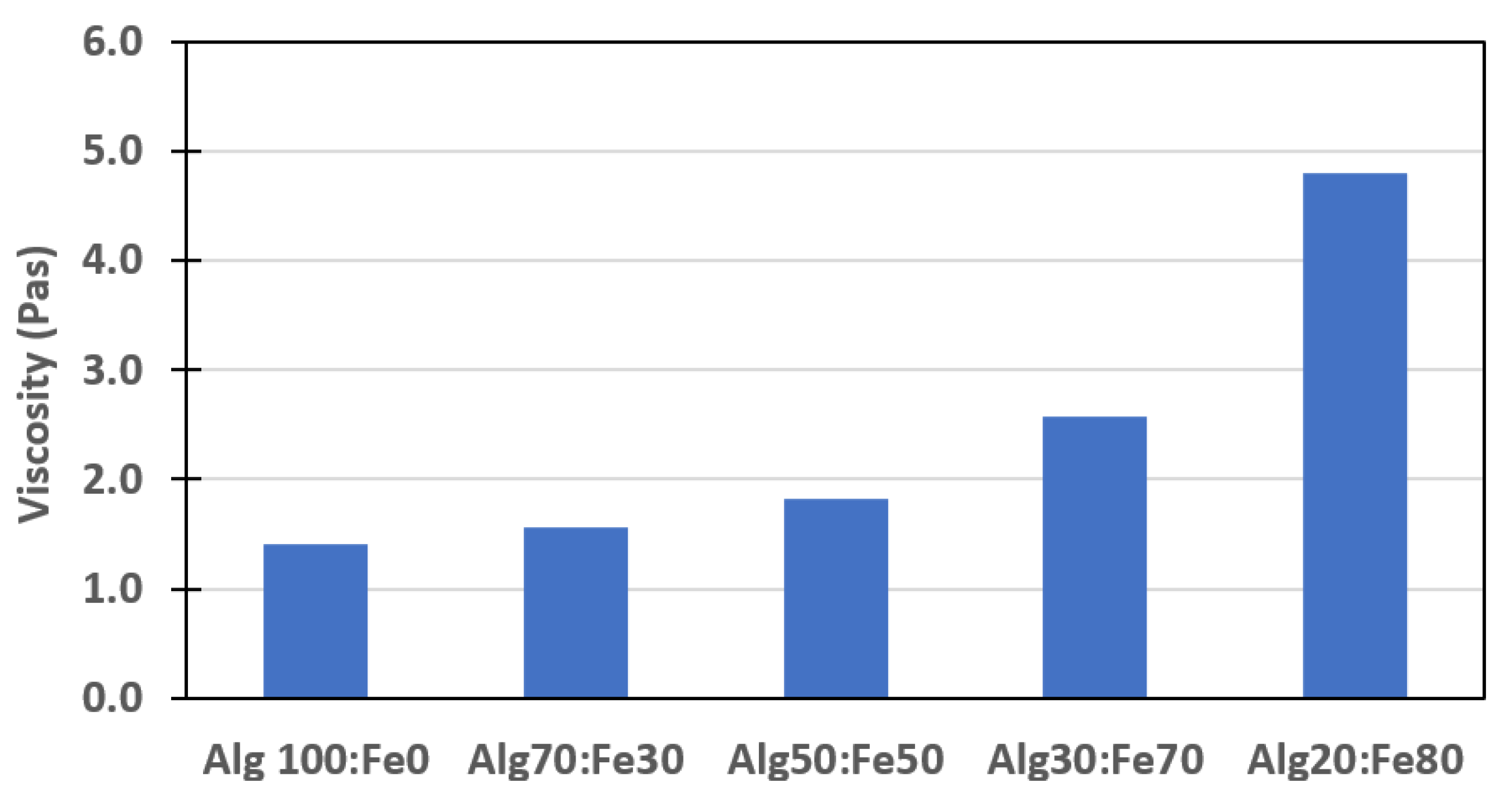
3.1. Alginate Solution Viscosity

Figure 7 shows the variation in viscosity of the alginate solution with the increasing iron powder content. The results show that iron content affects the solution viscosity. Increasing the iron content from 0% to 80% by weight increases the viscosity 3.4 times. It is also expected that capsules containing higher amounts of iron will be much denser than the alginate capsules encapsulating oil only.

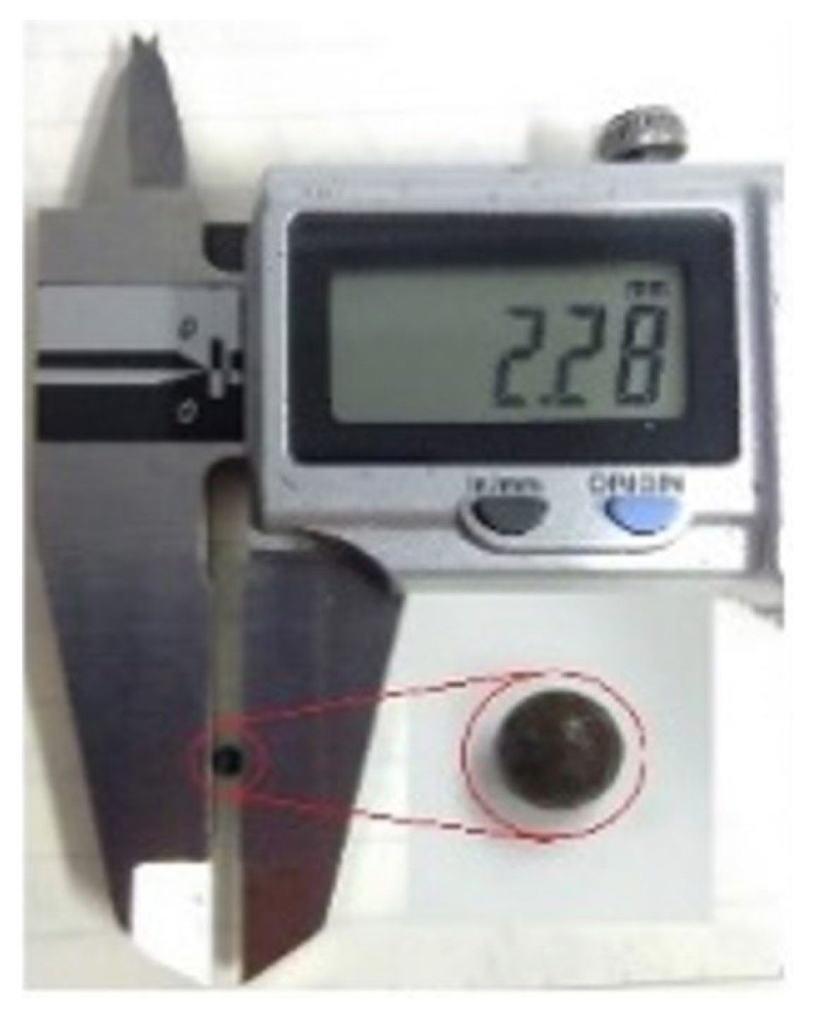
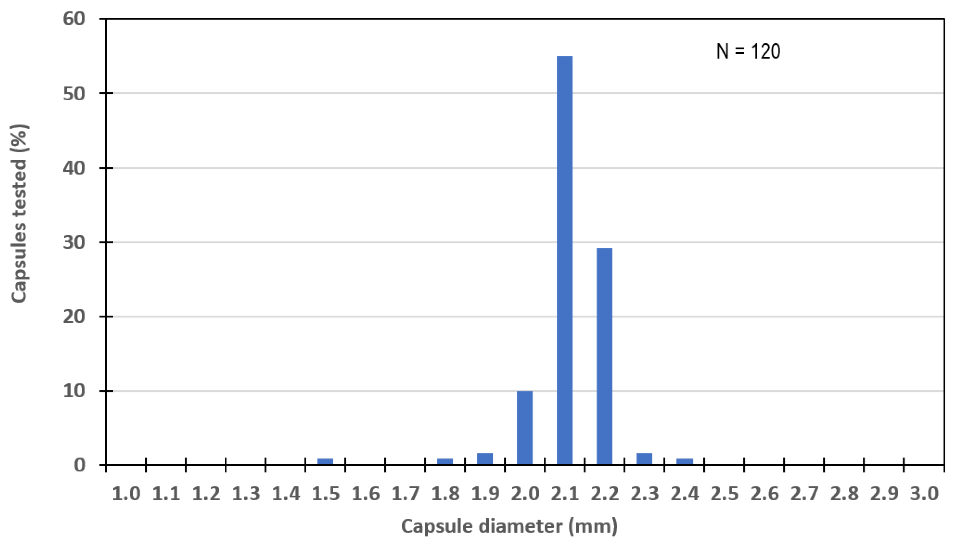
3.2. Capsule Size Distribution

The capsule size distribution was recorded by taking a random sample of 120 capsules (30 capsules from four Alg:Fe ratios, ranging from Alg 70:Fe 30 to Alg 20:Fe 80) and measuring the diameter manually using the digital Vernier callipers. Figure 2 illustrates the diameter measuring process. Figure 8 shows the dry capsule size distribution, with the results showing capsule dimeter ranges between 1.5 mm to 2.4 mm, with over 50% of capsules of 2.1 mm in diameter, 10% of 2 mm, and 29% of 2.2 mm. The results show that capsules were of a very regular and consistent size.

3.3. Capsule Relative Density
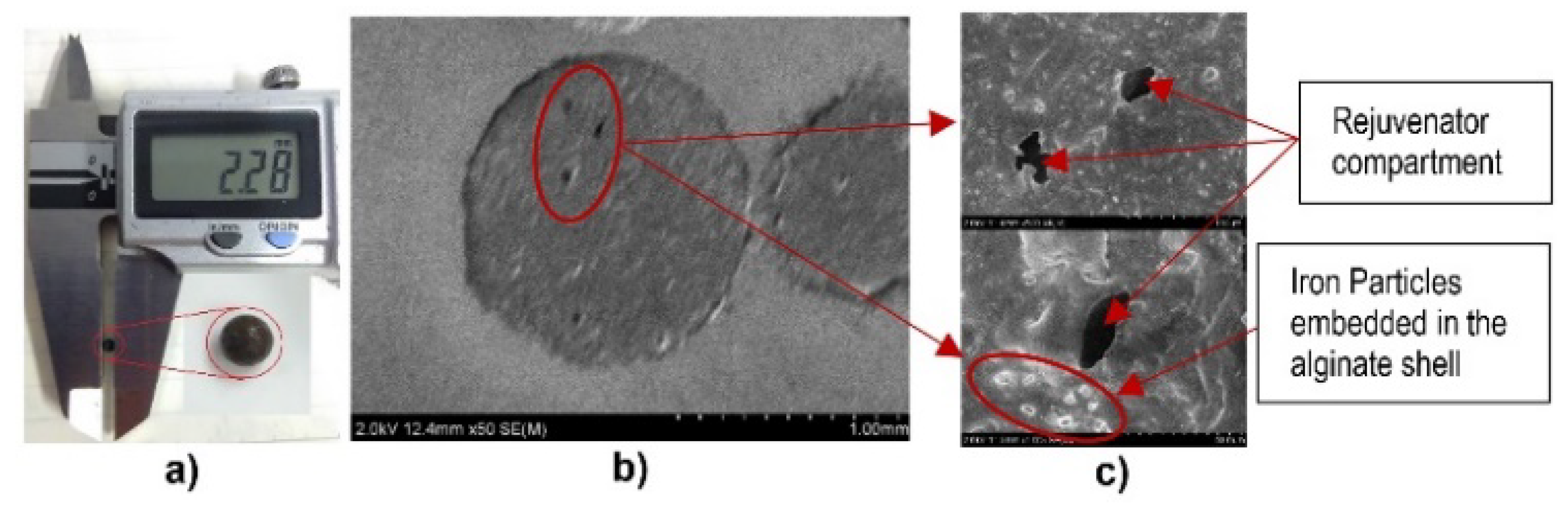
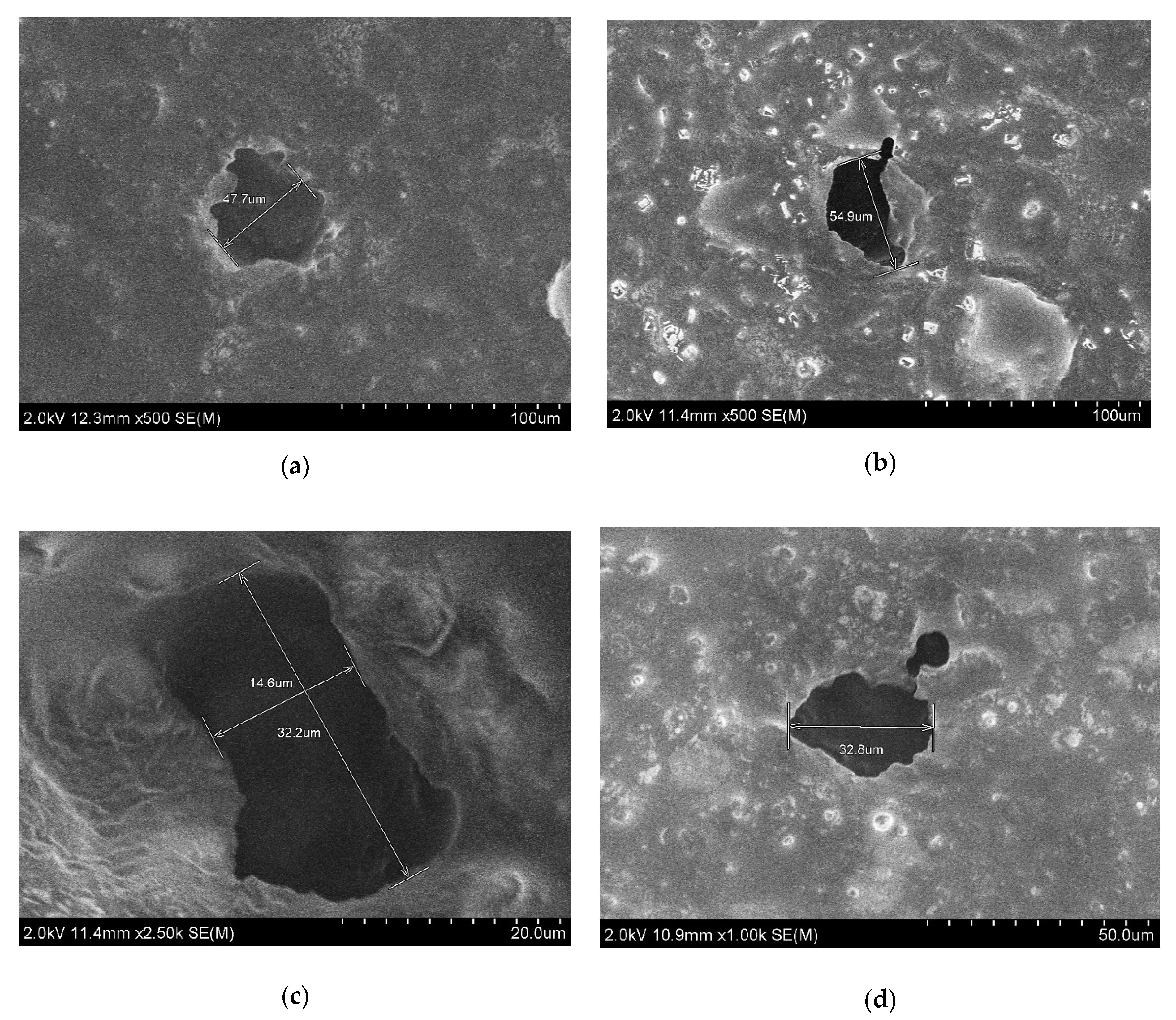
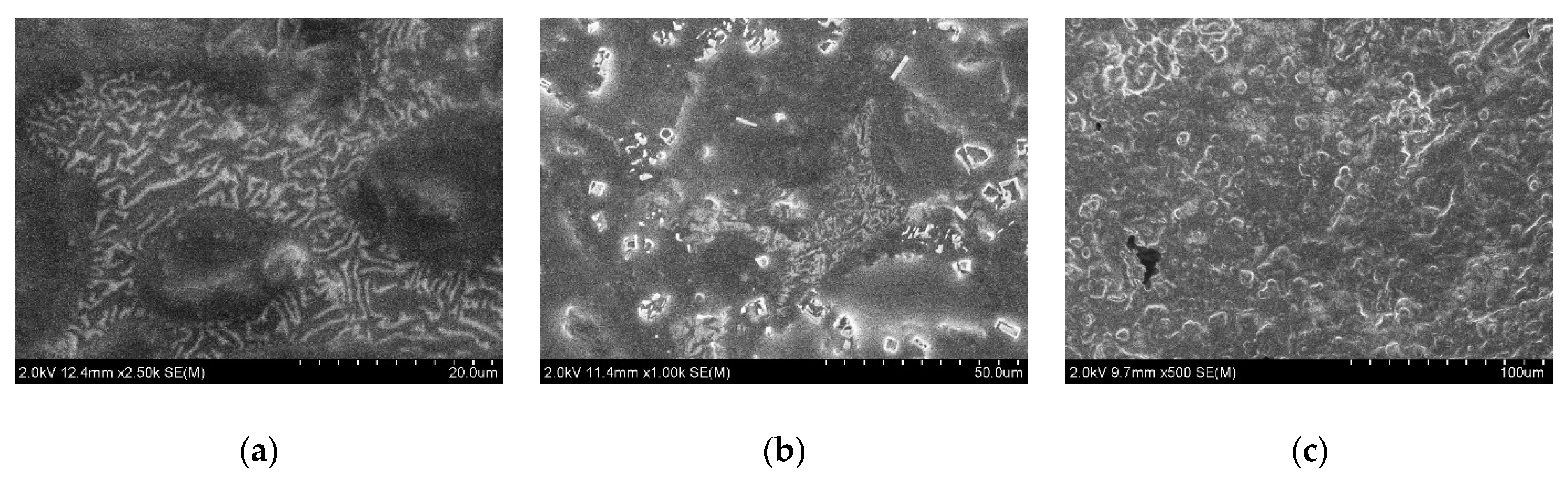
Table 2 summarises the relative density values for each capsule mix. The results show that the density of the capsules increases with the increase of iron powder in the capsule mix.

3.4. Capsule SEM

Figure 9 illustrates the SEM image of the capsule cross section. The figure shows that the body of the capsule is much denser than the alginate only capsule [25]. Iron particles are well distributed throughout the body of the capsule with rejuvenating oil pockets, within the capsule structure.
Figure 10 shows the cross-sectional image of the capsules with varying alginate (Alg)/iron powder (Fe) ratioss. The images show that capsules are much denser in comparison with the alginate capsule structure reported by Xu et al. [17] and Wan et al. [15] for capsules encapsulating magnetite and oil.
Figure 11 illustrates the bitumen rejuvenating pockets within the capsule structure. It is clear from the images that the alginate/iron power ratio has no significant influence on the size of the oil pockets within the capsule. This is in agreement with the findings from the literature [16,17], where it is stated that capsule size is dependent on the mixing rate and less on the oil content. The reduction in the oil content in the mix is due to the reduction of alginate in the mix. With increasing the iron powder content, the alginate content is reduced and, as a result, the oil content is also reduced. Figure 12 shows the iron powder patterns within the capsule alginate structure. The images show that the patterns change between the lower iron content capsules (Alg 70:Fe 30 and Alg 50:Fe 50) and higher iron content capsules (Alg 20:Fe 80).

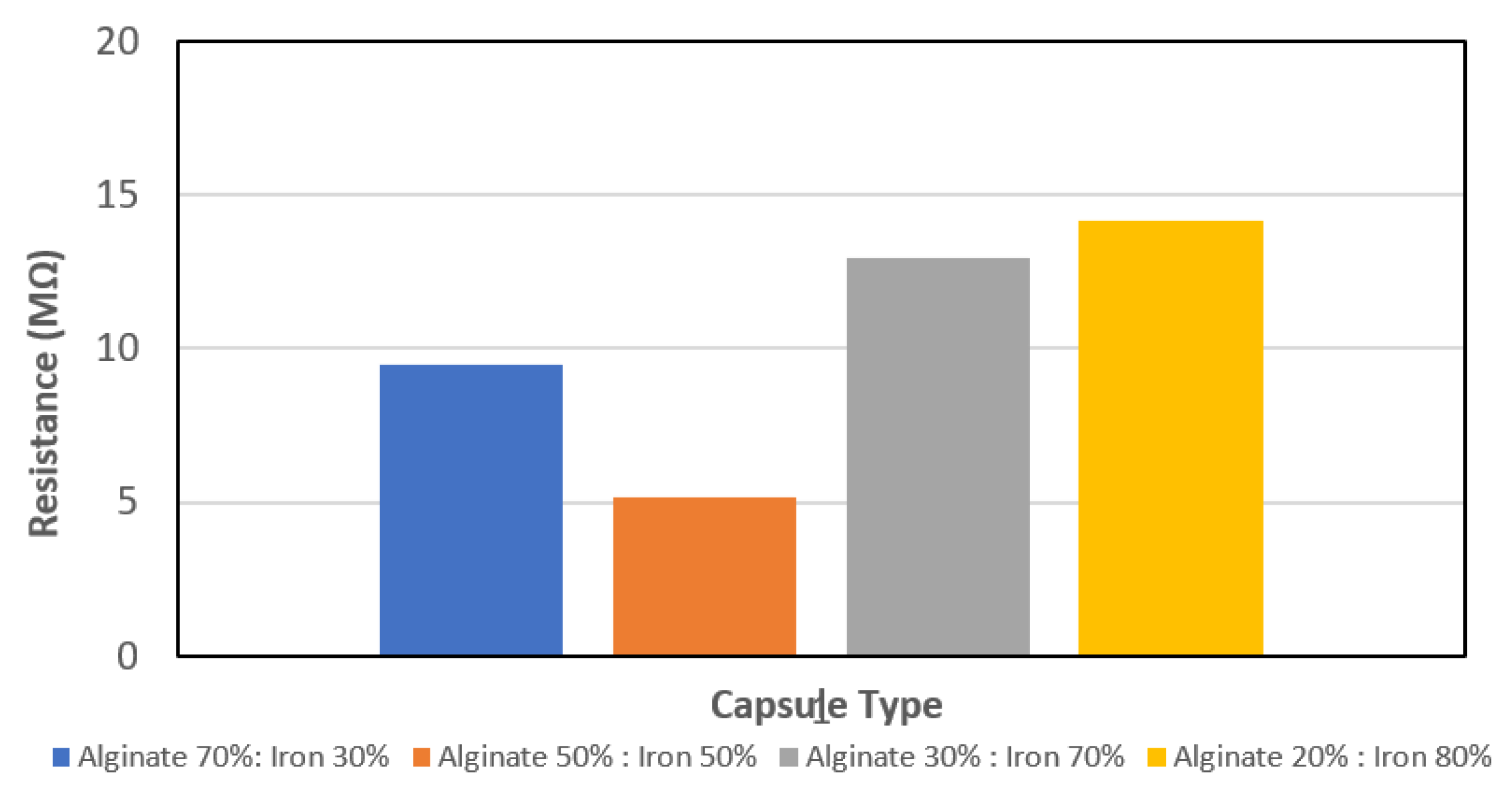
3.5. Capsule Resistivity
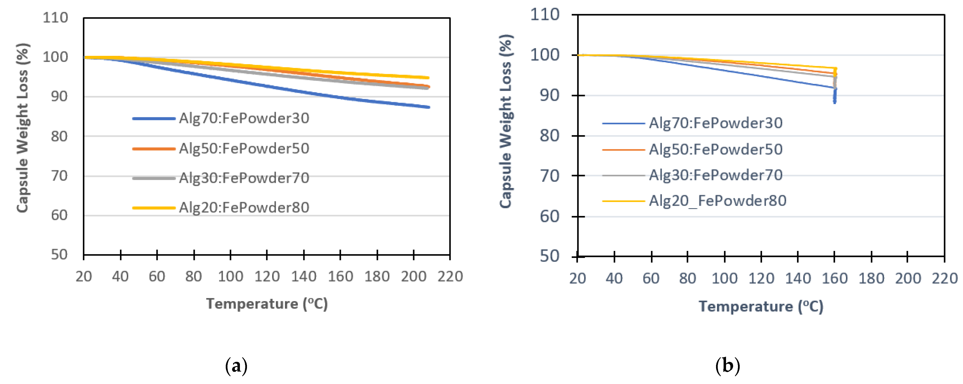
From the start, the capsules showed the magnetic properties. All of the capsule mix types were attracted to the magnetic field, see Figure 13. However, additional tests were necessary to determine whether the capsules would be capable of efficiently conducting the induction energy, because conductive “iron (Fe)” particles were embedded in the alginate coating, where alginate could act as an insulator, thus preventing the induction energy flow. Figure 14 summarises the results from the capsule resistance test. The tests show that the mixtures had resistance to the current flow, indicating their ability to conduct inductive energy. As expected, the capsules containing the highest concentration of iron powder (Alg 20:Fe 80) showed the highest resistance. The resistance gradually increased with the increase of the iron powder content in the mix, except for the mix containing equal amounts of alginate and iron powder (Alg 50:Fe 50). It is not precisely clear why this occurred, however, two reasons are proposed. Firstly, the capsules might not have been fully dehydrated and thus had a higher moisture content. However, the TGA test data, see Figure 15, did not confirm this hypothesis. The second reason might be a structure imbalance at this mix ratio. Figure 16 and Figure 19 show similar behaviour, where the capsule strength is lower than that of the capsules containing a higher mount of alginate.

3.6. Capsule TGA

The biggest concern for the conductive alginate capsules encapsulating a bitumen rejuvenator is whether they can withstand the asphalt mixing temperatures during asphalt manufacturing process, which are between 160 °C and 180 °C [16]. For this reason, TGA tests were used to replicate the processing conditions. Two tests were designed; one that simulates the asphalt mixing temperatures and a second that simulates the asphalt transport temperature (heat and hold for 1 h). Figure 15a shows the TGA test results of the capsules containing varying alginate/iron powder ratios. The capsules were subjected to ramp heating from room temperature (20 ± 3 °C) to 200 °C at rate of 10 °C/min. The results show that the maximum weight loss is 12% for the capsules of Alg:Fe with a ratio of 70:30, and the minimum is 5% for the 20:80 Alg:Fe capsule ratio. This is because the capsules hold the moisture in the alginate rather than the iron. As result, after the drying process, it is expected that the capsules with the higher alginate content will experience a greater weight loss. Similar findings were reported previously by Tabaković et al. [16] and Xu et al. [17]. Nevertheless, capsules containing a high amount of iron powder (Alg 20:Fe 80) showed a weight loss of only 5% at 200 °C. The heat and hold test in Figure 15b showed similar results, with the highest weight loss for mixtures with higher alginate and lower iron powder content. The weight loss continued while the temperature was held at max 160 °C, losing an additional 3–4% of the weight. This is expected, as capsules will keep losing weight while moisture evaporates from the capsules. These results indicate that conductive alginate capsules encapsulating a bitumen rejuvenator have a suitable thermal resistance to withstand the standard asphalt production process.

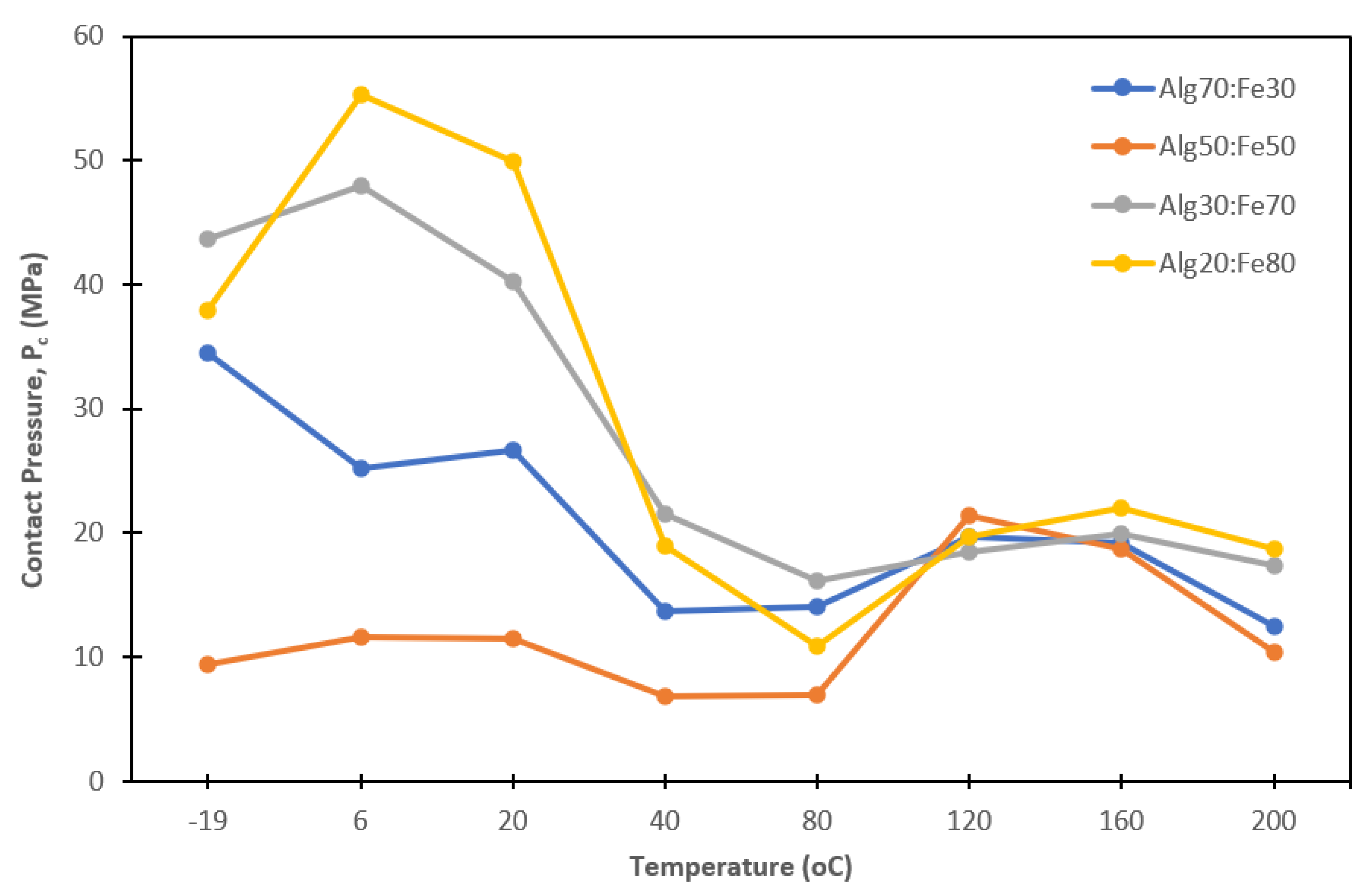
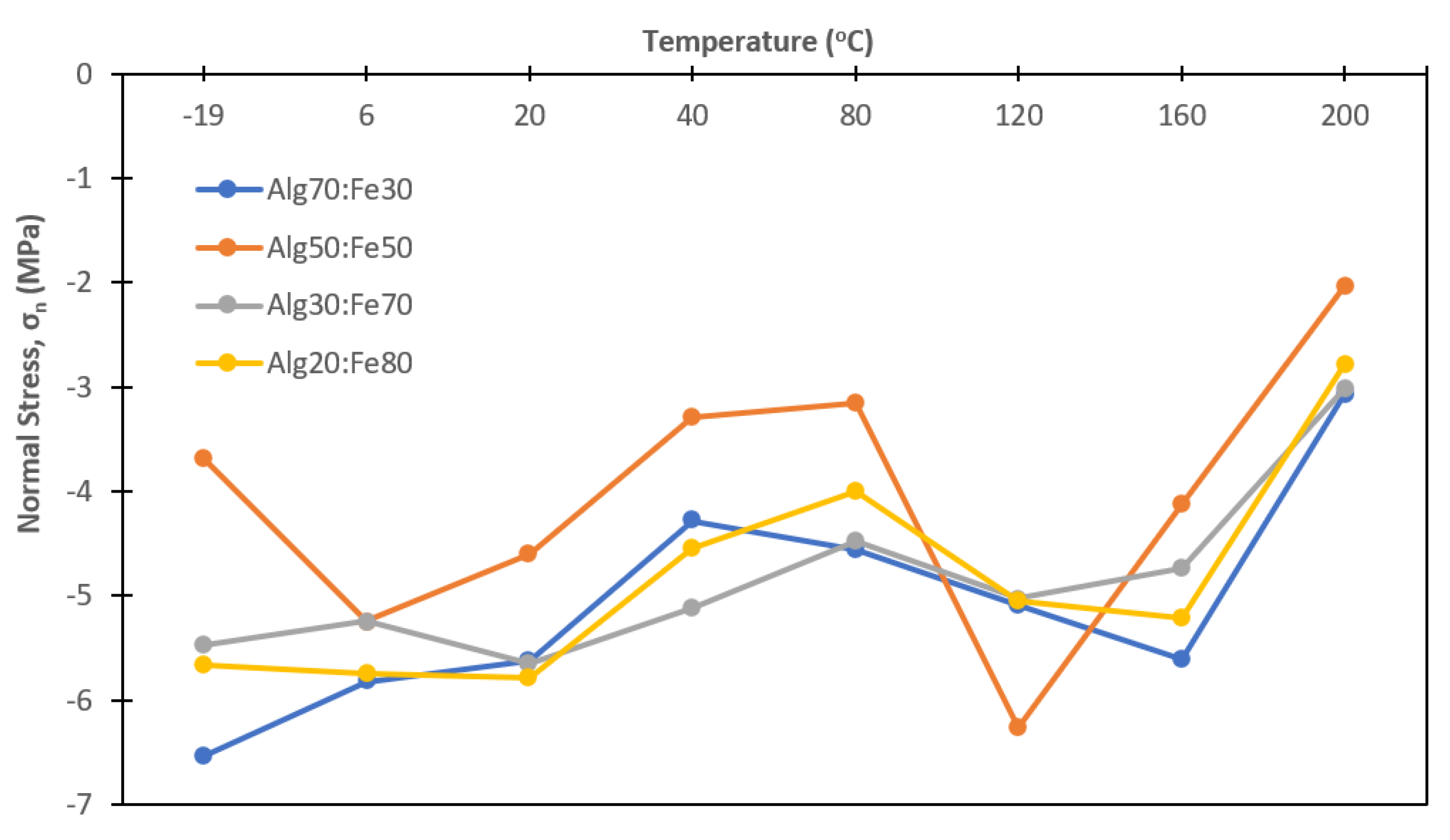
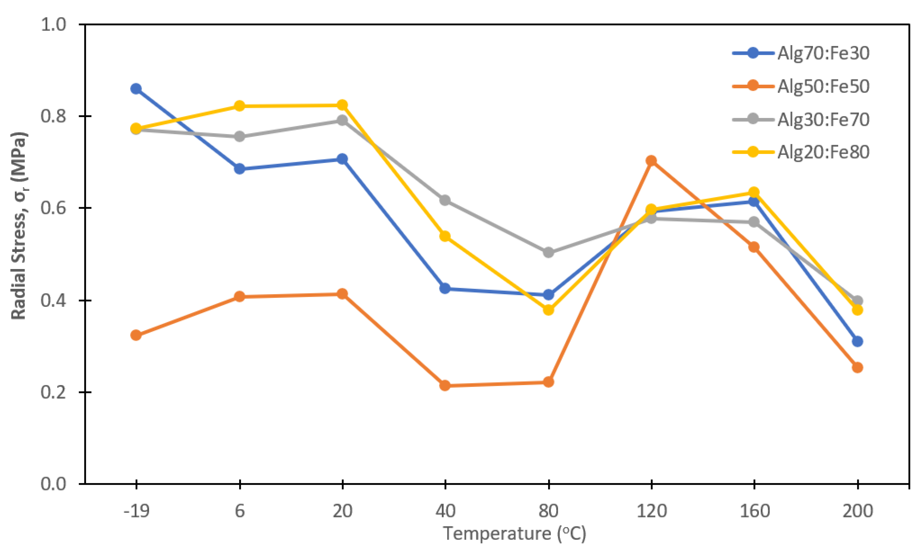
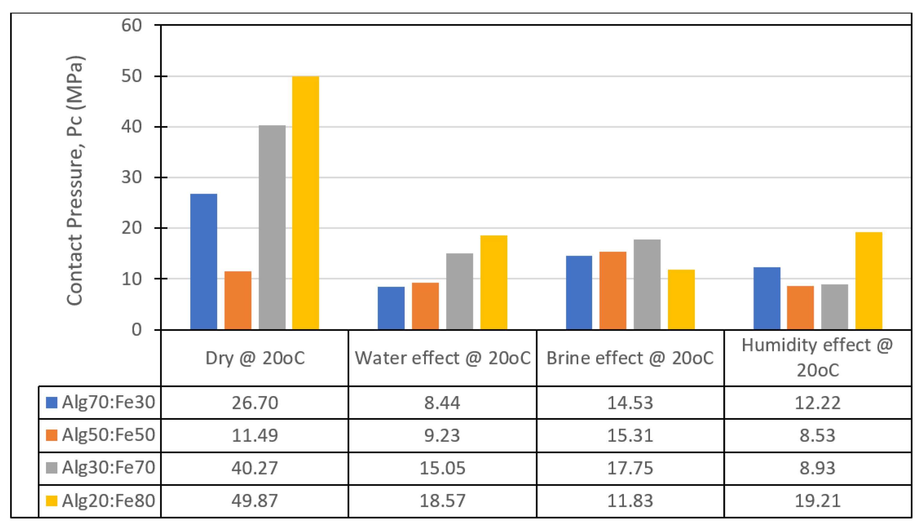
3.7. Capsule Compressive Strength

Another very important question in the capsule design process is whether they can withstand harsh (thermal and loading) conditions during the asphalt (bituminous) mix production. For this reason, the effect of the temperature, moisture, humidity, and salt on the compressive failure strength of conductive alginate capsules encapsulating a bitumen rejuvenator were investigated.
Figure 16 illustrates the compression test results from the thermal effect test. The results show that temperature does indeed have a strong effect on the capsule strength, with Alg 20:Fe 80 capsules showing the highest variation across the temperature range (−19 °C–200 °C). However, the pressure stabilised after 80 °C. It is believed that moisture residue within the capsule affects the capsule strength at lower temperatures (<80 °C), thus after moisture evaporation, the capsule strength stabilises at a higher temperature >80 °C.
Figure 17 and Figure 18 show the normal and radial stress within the capsule at the maximum pressure contact, at varying temperatures. Similarly as for contact pressure, capsules experience high stress at lower temperature and as temperature increases, up to 80 °C, stresses decrease, which is expected because residual moisture within the capsules soften the alginate. As the temperature passes 80 °C, the stresses increase again up until 160 °C. This is because excess moisture in the capsule evaporates and capsules become more brittle. However, at 200 °C, the capsule stress starts to fail. At this point, the alginate within the capsule starts to disintegrate and the capsule loses its structural integrity.
Figure 19 shows the effect of water, brine, and humidity on the capsules’ compressive strength. A dry capsule was used as the control sample. The results show that all three methods of pre-conditioning have a significant effect on all capsule mixtures, except the Alg 50:Fe 50 capsule mix. The results show that the capsule compressive strength improves with exposure to the salt water (brine). However, the strength of the capsules decreases by more than 50% for mixtures Alg 70:Fe 30; Alg 30:Fe 70, and Alg 20:Fe 80 when subjected to water, brine, and humidity. This could possibility be because the capsules absorb the moisture when exposed to a moist environment, becoming softer and thus experiencing a reduction in the strength. Table 3 shows the capsule test samples weights before and after conditioning. The results confirm that there was an increase in the weight gain of the capsules, indicating that the test samples did absorb moisture during the conditioning phase, thus resulting in softer capsules with reduced strength. However, it is assumed that this will not have great effect on the capsule healing performance, as the heat generated by the induction radiation will increase the capsule temperature and dry it, allowing it to recover its initial (dry) strength.

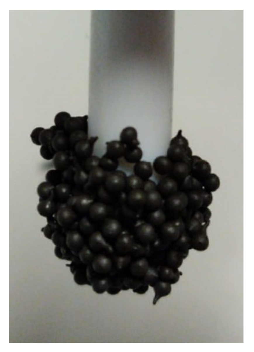
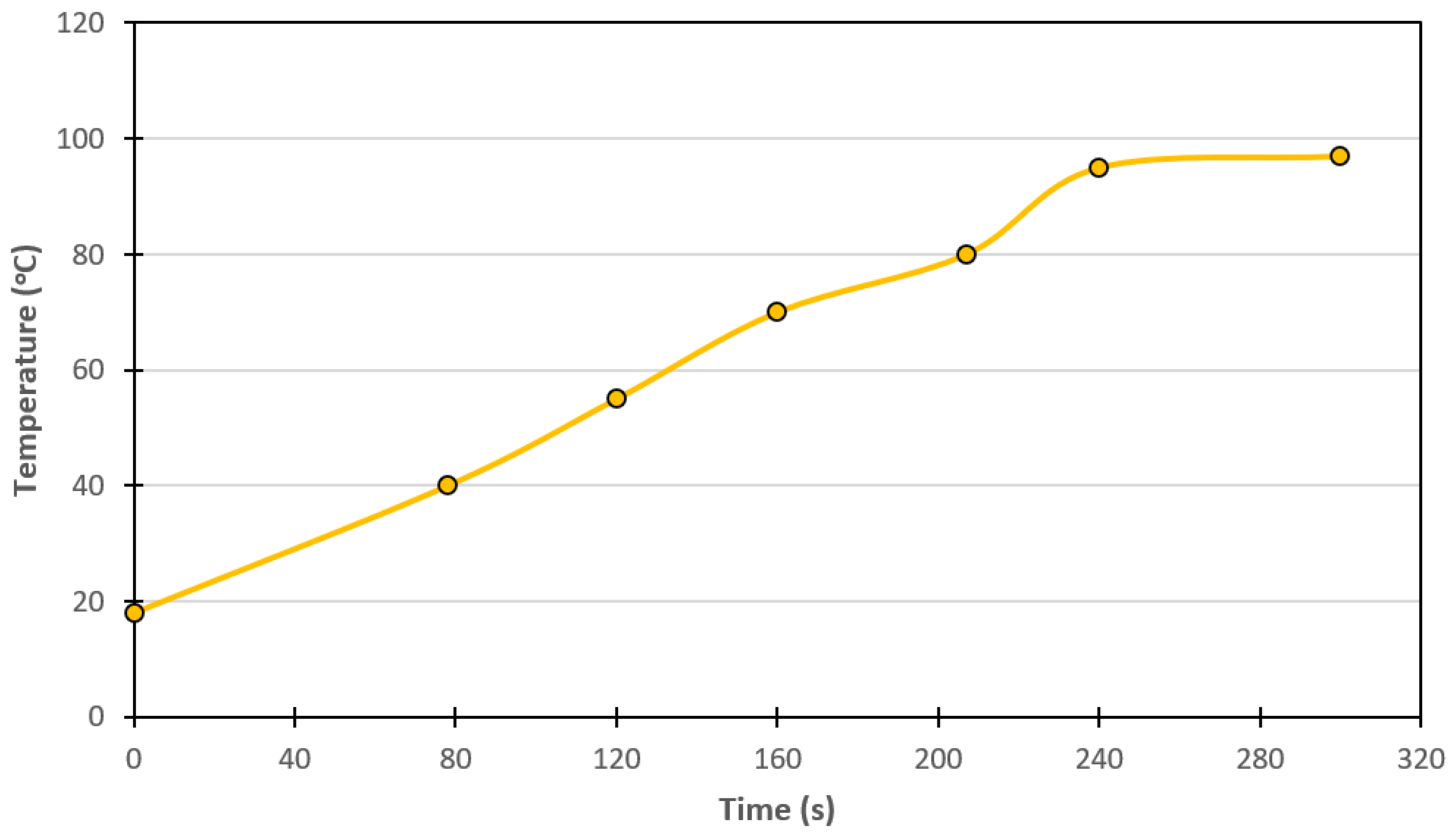
3.8. Capsule Induction

Capsule induction was carried out in order to determine whether capsules can conduct induction energy, and if they do, what the maximum temperature is each capsule mix can reach. The test was performed at 5.6 kW and a 109 Hz induction machine energy output. A solenoid coil was used for energy induction and the capsules were placed in a glass beaker with a 9 mL volume. The maximum time allowed for the test was 300 s (5 min). Table 4 summarises the test results for all four capsule types. From the data, it is obvious that only the Alg 20:Fe 80 ratio capsule reached the desired temperature (>80 °C). Figure 20 shows the capsule Alg 20:Fe 80 temperature rise. The results show that temperature reached a maximum temperature at 97 °C. Following the work in Liu et al. [26], the adequate temperature for asphalt healing is 80 °C, as such, this Alg 20:Fe80 capsule design was adopted for inclusion in the bitumen and mortar mixes.

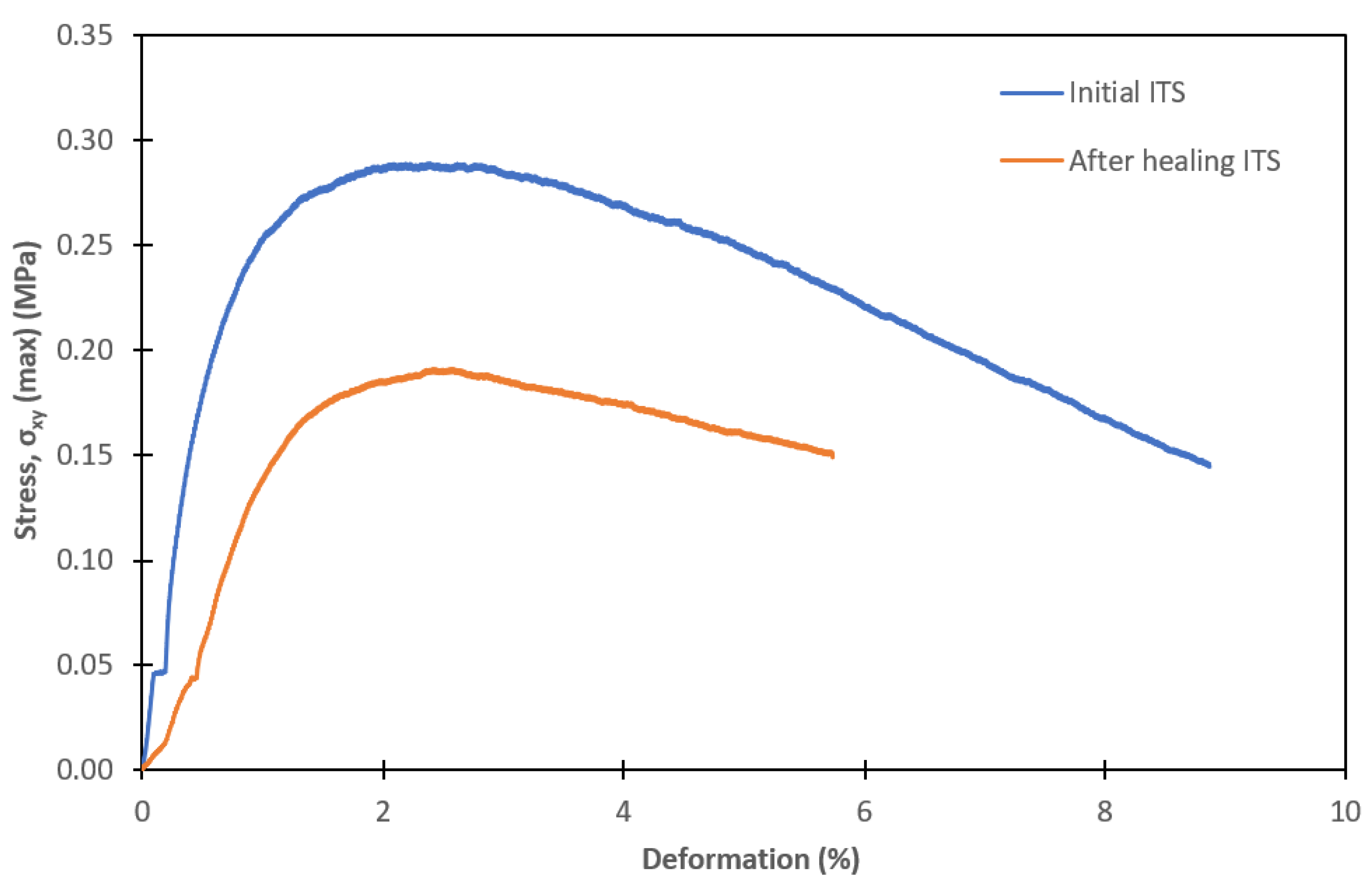
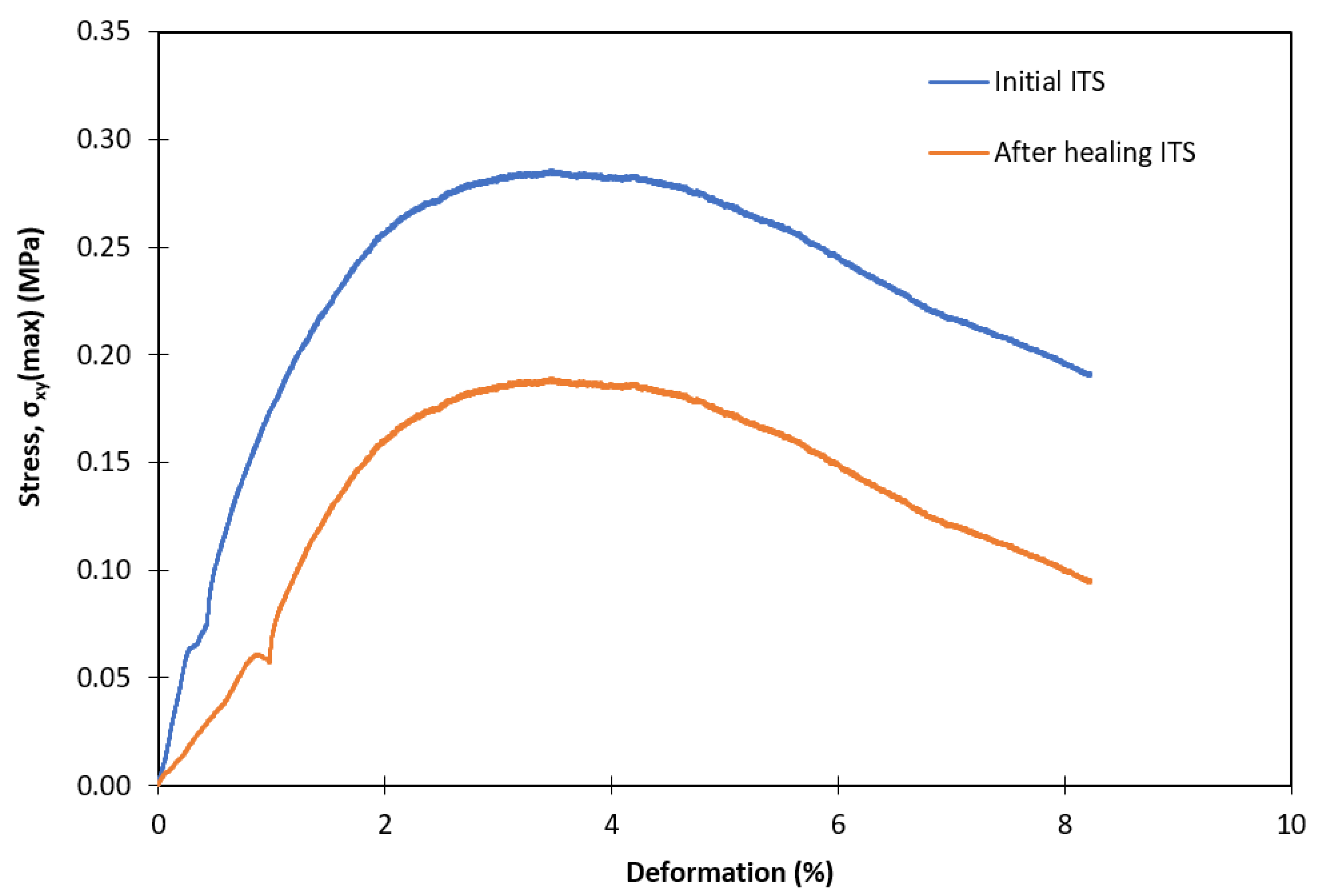
3.9. Indirect Tensile Strength of Mortar and Bitumen Test Specimens

The bitumen and bitumen mortar mix ITS–induction (healing) tests showed the capsules’ potential to repair crack damage in a bitumen and bitumen mortar mix within 5 min of being subjected to induction heating, at an energy output 759 V and frequency 109 kHz. Figure 21 shows healing of a completely disintegrated bitumen test sample containing 10% capsules, within 5 min of healing time.
The bituminous tests containing 10% and 20% of capsules were successfully extracted from the moulds and tested. However, as the test specimens were too soft to be tested at room temperature of 20 ± 3 °C, they had to be submerged in liquid nitrogen for 10 s. As a result, all of the test specimens disintegrated at the maximum load. Figure 21 shows the testing and healing process. Figure 22 shows the summary ITS and induction healing test results, and the results show a very high specimen strength recovery. Test specimens containing 10% capsules recovered 94% of their initial strength, whereas specimens containing 20% capsules experienced 118% strength recovery. These results indicate that conductive alginate capsule encapsulating a bitumen rejuvenating oil is suitable the healing system of the bituminous mixtures.
Even though the ITS bituminous tests showed promising results, the question is whether the system is suitable for healing bituminous mixtures containing aggregates. Tabakovic et al. [1,19] showed that even though a self-healing system can be very efficient at healing bitumen only damage, it has limited healing efficiency in a full bituminous mix (bitumen and aggregates). Therefore, the next step was to perform the tests on an ITS mortar mix containing conductive alginate capsule encapsulating a bitumen rejuvenating oil. Figure 23 and Figure 24 show the mortar mix, containing 5% and 10% capsules in the mix, strength recovery 66% and 67%, respectively, after full breakage. These results indicate that conductive alginate capsules encapsulating a rejuvenator (Alg 20:Fe 80) can successfully repair a crack in a bituminous mix.

4. Discussion

The upscaled capsule production process allows for the production of large quantities of capsules, paving the way for suitable capsule production for an on-site testing. The data presented in Figure 8 show very consistent capsule size production. SEM images in Figure 10 and Figure 11 show that capsules with a higher amount of iron have a denser inner structure in comparison with the capsules without conductive iron particles.
The thermal effect on the capsule compression strength results showed that temperature indeed has a strong effect on the capsule strength, see Figure 16, with Alg 20:Fe 80 capsules showing the highest variation across the temperature range (−19–200 °C). However, the pressure stabilises after 80 °C. It is believed that moisture residue within the capsule affects the capsule strength at lower temperatures (< 80 °C), thus after moisture evaporation, the capsule strength stabilises at higher temperatures > 80 °C.
The effect of water, brine, and humidity on the capsules’ compressive strength in Figure 19 shows that all three methods of pre-conditioning have a significant effect on all capsule mixtures, except the Alg 50:Fe 50 capsule mix. The results show that the capsule compressive strength improved with exposure to the salt water (brine). However, the strength of the capsules decreased by more than 50% for mixtures Alg 70:Fe 30; Alg 30:Fe 70, and Alg 20:Fe 80 when subjected to water, brine, and humidity. A reason the Alg 50:Fe 50 ratio capsules are less affected could due to the iron distribution within the capsule. Figure 12 suggests that the percentage of iron powder effects the phase separation of the alginate and iron powder. For example, Figure 12a (Alg 70:Fe 30) suggests the iron is more evenly spread out in elongated regions. While 12b (Alg 50: Fe 50) looks amalgamated in areas throughout the capsule body. These results suggest that there could be a continuous and discontinuous phase separation within the capsule mix. Thus, it is easier for water to ingress in a Alg 70:Fe 30 structure like Figure 12a.
The capsule induction test results in Table 4 show that only the Alg 20:Fe 80 ratio capsule can be used in bitumen mix healing, as it is only one that can reach a temperature over 80 °C, with a max temperature at 97 °C. The efficacy of the Alg 20:Fe 80 ratio capsule as a bitumen mix extrinsic self-healing was proven by carrying out bitumen only and bitumen mortar mix ITS tests. The test result, see Figure 22, Figure 23 and Figure 24, show that capsule reinforced the bitumen and bitumen mortar mixtures, i.e., increasing the amount of capsules in the bitumen and bitumen mortar results with a higher initial strength. The results also show (Figure 22, Figure 23 and Figure 24) conductive alginate capsules encapsulating a bitumen rejuvenator can successfully repair the damage (close cracks) in a bitumen and bitumen mortar mix with an efficiency of up to 118% for the bitumen specimens and 67% for the mortar specimens.

5. Conclusions

The research results have shown that conductive alginate capsules encapsulating a bitumen rejuvenator has potential as an asphalt pavement healing system. The results showed that capsules have sufficient physical, mechanical, and thermal strength to be included in an asphalt mix design as an extrinsic self-healing system. The induction heating results suggest that capsules of Alg 20:Fe 80 are capable to conduct inductive energy and transmit it to the sounding environment (bitumen), softening it and allowing it to flow and repair the damage, closing the cracks. However, the results also show that healing efficiency decreases with the inclusion of the aggregates into the bitumen mix. Thus, it is expected that the efficiency of the conductive alginate capsules encapsulating a bitumen rejuvenator as a self-healing system will reduce with the inclusion of larger volume of aggregates in the bituminous mix. Therefore, the next step is to evaluate and optimize the conductive alginate capsules encapsulating a bitumen rejuvenator in a full bituminous (asphalt pavement) mix.

6. Patents

An Intellectual Property application titled: “A Conductive Alginate Capsule Encapsulating a Healing Agent”, was submitted by the TU Dublin and Amir Tabaković to the UK Intellectual Property Office. The objective of the IP application is to ring-fence specific capsule formulation for potential production and licensees’ particular applications.

Author Contributions

Conceptualization, A.T.; methodology, A.T.; validation, A.T., J.M. and A.K.; formal analysis, A.T. and A.K.; investigation, A.T.; resources, A.T.; data curation, A.T.; writing—original draft preparation, A.T.; writing—review and editing, A.T., J.M. and A.K.; visualization, A.T.; project administration, A.T.; funding acquisition, A.T. All of the authors have read and agreed to the published version of the manuscript.

Funding

This research was funded by the Enterprise Ireland, grant number CF 20191063P.

Acknowledgments

The authors would like to acknowledge the support of Lagan Material, Ltd., for providing valuable advice and the bituminous material used for the ITS test. The authors would also like to acknowledge the contribution of Alicia Kaworek for her assistance in setting up and carrying out the viscosity tests.

Conflicts of Interest

The authors declare no conflict of interest. The funders had no role in the design of the study; in the collection, analyses, or interpretation of data; in the writing of the manuscript; or in the decision to publish the results.

References

  1. Tabaković, A.; Braak, D.; Van Gerwen, M.; Copuroglu, O.; Post, W.; Garcia, S.J.; Schlangen, E. The compartmented alginate fibres optimisation for bitumen rejuvenator encapsulation. J. Traffic Transp. Eng. 2017, 4, 347–359. [Google Scholar] [CrossRef]
  2. Xu, S.; García, A.; Su, J.; Liu, Q.; Tabaković, A.; Schlangen, E. Self-Healing Asphalt Review: From Idea to Practice. Adv. Mater. Interfaces 2018, 5, 1800536. [Google Scholar] [CrossRef]
  3. Tabaković, A.; Schlangen, E. Self-Healing Technology for Asphalt Pavements. In Self-Healing Materials; Hager, M.D., van der Zwaag, S., Schubert, U.S., Eds.; Springer International Publishing: Cham, Switzerland, 2016; pp. 285–306. [Google Scholar]
  4. Leegwater, G.; Tabokovi, A.; Baglieri, O.; Hammoum, F. Terms and definitions on crack-healing and restoration of mechanical properties in bituminous materials. In Proceedings of the RILEM International Symposium on Bituminous Materials, Lyon, France, 8–10 June 2020. [Google Scholar]
  5. Seneviratne, S.; Tabaković, A. Self-Healing Asphalt HealRoad Customer Discovery and Needs Analysis Report; Unpublished; 2020. [Google Scholar]
  6. GOV.UK. Road Accidents and Safety Statistics. 2021. Available online: https://www.gov.uk/government/collections/road-accidents-and-safety-statistics (accessed on 5 February 2021).
  7. Safety, N.W.Z. Work Zone Fatal Crashes and Fatalities. 2021. Available online: https://www.workzonesafety.org/crash-information/work-zone-fatal-crashes-fatalities/#national (accessed on 5 February 2021).
  8. Butt, A.A.; Brigisson, B.; Kringos, N. Optimizing Highway Lifetime by Improving the Self-Healing Capacity of Asphalt. Procidia Soc. Behav. Sci. 2012, 48, 2190–2200. [Google Scholar] [CrossRef] [Green Version]
  9. García, Á.; Schlangen, E.; van de Ven, M.; Liu, Q. Electrical conductivity of asphalt mortar containing conductive fibers and fillers. Constr. Build. Mater. 2009, 21, 3175–3181. [Google Scholar] [CrossRef]
  10. García, Á.; Schlangen, E.; van de Ven, M.; Liu, Q. A simple model to define induction heating in asphalt mastic. Constr. Build. Mater. 2012, 31, 38–46. [Google Scholar] [CrossRef]
  11. Liu, Q. Induction Healing of Porous Asphalt Concrete. Ph.D. Thesis, Delft University of Technology, Delft, The Netherlands, 2012. [Google Scholar]
  12. Bueno, M.; Arraigada, M.; Partl, M.N. Damage detection and artificial healing of asphalt concrete after trafficking with a load simulator. Mech. Time Depend. Mater. 2016, 20, 265–279. [Google Scholar] [CrossRef]
  13. Norambuena-Contreras, J.; Garcia, A. Self-healing of asphalt mixture by microwave and induction heating. Mater. Des. 2016, 106, 404–414. [Google Scholar] [CrossRef]
  14. Norambuena-Contreras, J.; Serpell, R.; Vidal, G.V.; González, A.; Schlangen, E. Effect of fibres addition on the physical and mechanical properties of asphalt mixtures with crack-healing purposes by microwave radiation. Constr. Build. Mater. 2016, 127, 369–382. [Google Scholar] [CrossRef]
  15. Wan, P.; Liu, Q.; Wu, S.; Zhao, Z.; Chen, S.; Zou, Y.; Yu, X. A novel microwave induced oil release pattern of calcium alginate/nano-Fe3O4 composite capsules for asphalt self-healing. J. Clean. Prod. 2021, 297, 126721. [Google Scholar] [CrossRef]
  16. Tabaković, A.; Post, W.; Cantero, D.; Copuroglu, O.; Garcia, S.J.; Schlangen, E.J.S.M.S. Reinforcement and healing of asphalt mixtures by rejuvenator encapsulation in alginate compartmented fibres. Smart Mater. Struct. 2016, 25, 084003. [Google Scholar] [CrossRef] [Green Version]
  17. Xu, S.; Tabaković, A.; Liu, X.; Schlangen, E. Calcium alginate capsules encapsulating rejuvenator as healing system for asphalt mastic. Constr. Build. Mater. 2018, 169, 379–387. [Google Scholar] [CrossRef] [Green Version]
  18. Gonzalez-Torre, I.; Norambuena-Contreras, J. Recent advances on self-healing of bituminous materials by the action of encapsulated rejuvenators. Constr. Build. Mater. 2020, 258, 119568. [Google Scholar] [CrossRef]
  19. Tabaković, A.; Schuyffel, L.; Karač, A.; Schlangen, E. An Evaluation of the Efficiency of Compartmented Alginate Fibres Encapsulating a Rejuvenator as an Asphalt Pavement Healing System. Appl. Sci. 2017, 7, 647. [Google Scholar] [CrossRef] [Green Version]
  20. Xu, S.; Liu, X.; Tabaković, A.; Schlangen, E. A novel self-healing system: Towards a sustainable porous asphalt. J. Clean. Prod. 2020, 259, 120815. [Google Scholar] [CrossRef]
  21. Zemskov, S.V.; Jonkers, H.M.; Vermolen, F.J. Two analytical models for the probability characteristics of a crack hitting encapsulated particles: Application to self-healing materials. J. Comput. Mater. Sci. 2011, 50, 10. [Google Scholar] [CrossRef]
  22. Tabaković, A.; Karač, A.; Ivanković, A.; Gibney, A.; McNally, C.; Gilchrist, M.D. Modelling the quasi-static behaviour of bituminous material using a cohesive zone model. Eng. Fract. Mech. 2010, 77, 2403–2418. [Google Scholar] [CrossRef]
  23. Mohan, J.; Ivanković, A.; Murphy, N. Effect of prepreg storage humidity on the mixed-mode fracture toughness of a co-cured composite joint. Compos. Part A Appl. Sci. Manuf. 2013, 45, 12. [Google Scholar] [CrossRef]
  24. Johnson, K.L. Contact Mechanics; Cambridge University Press: Cambridge, UK, 1985. [Google Scholar]
  25. Xu, S.; Tabakovic, A.; Schlangen, E.; Liu, X. Alginate Capsules Encapsulating Rejuvenator as Self-healing System for Porous Asphalt Concrete; HelCON: Delft, The Netherlands, 2016. [Google Scholar]
  26. Liu, Q.; Schlangen, E.; García, Á.; van de Ven, M. Induction heating of electrically conductive porous asphalt concrete. Constr. Build. Mater. 2010, 24, 1207–1213. [Google Scholar] [CrossRef]
Figure 1. Capsule production laboratory system.
Processes 09 01361 g001
Figure 2. Conductive alginate capsule encapsulating a bitumen rejuvenator oil.
Processes 09 01361 g002
Figure 3. Bitumen ITS test specimen: (a) Struers FixiForm 30 mm diameter, (b) specimen prepared in the mould, (c) test specimen, and (d) ITS test set up.
Processes 09 01361 g003
Figure 4. Schematic illustration of Indirect Tensile Strength (ITS) test: (a) Indirect tensile loading, (b) Stress distribution in an indirect tensile test specimen.
Processes 09 01361 g004
Figure 5. Electrical resistivity apparatus set up: (a) ITT Matrix MX 545 digital mustimeter and (b) positioning of current transferring pins and capsule.
Processes 09 01361 g005
Figure 6. Ambrell Ekoheat 10 kW Induction Machine.
Processes 09 01361 g006
Figure 7. Alginate solution containing varying iron (Fe) powder content viscosities.
Processes 09 01361 g007
Figure 8. Capsule size distribution.
Processes 09 01361 g008
Figure 9. (a) Capsule image, (b,c) cross section of the microscopic (SEM) image of the capsule.
Processes 09 01361 g009
Figure 10. SEM capsule images: (a) Alg 70:Fe30; (b) Alg 50:Fe 50; (c) Alg 30:Fe 70; (d) Alg 20:Fe 80.
Processes 09 01361 g010
Figure 11. Rejuvenating oil pockets within varying capsule mixtures: (a) Alg 70:Fe30; (b) Alg 50:Fe50; (c) Alg 30:Fe 70; (d) Alg 20:Fe 80.
Processes 09 01361 g011
Figure 12. Iron powder (bright areas) distribution throughout the capsule: (a) Alg 70:Fe30; (b) Alg 50:Fe50; (c) Alg 20:Fe 80.
Processes 09 01361 g012
Figure 13. Capsule magnetism.
Processes 09 01361 g013
Figure 14. Capsule resistance.
Processes 09 01361 g014
Figure 15. Conductive alginate capsule encapsulating rejuvenator oil thermogravimetric analysis (TGA) test results, (a) ramp temperature load, (b) ramp temperature load, up to 160 °C and held for 1 h.
Processes 09 01361 g015
Figure 16. Thermal effect on the capsule Contact Pressure (Pc).
Processes 09 01361 g016
Figure 17. Thermal effect on the capsule for normal stress at middle of the capsule (σn).
Processes 09 01361 g017
Figure 18. Thermal effect on the capsule for radial stress at middle of the capsule (σr).
Processes 09 01361 g018
Figure 19. Effect of water, salt, and humidity on capsule compressive strength.
Processes 09 01361 g019
Figure 20. Inductive heating (temperature rise vs. time) of Alg 20:Fe 80 capsules.
Processes 09 01361 g020
Figure 21. Capsule (mortar mix test specimen containing 10% capsule by weight) conductivity testing; (a) bitumen mix indirect tensile loading, (b) disintegrated test specimen, (c) induction heating/healing (5 min), and (d) restored test specimen.
Processes 09 01361 g021
Figure 22. Bitumen ITS and induction healing test results.
Processes 09 01361 g022
Figure 23. Mortar mix strength for ITS test specimens containing 5% capsules recovery after 5 min of induction healing.
Processes 09 01361 g023
Figure 24. Mortar mix strength for ITS test specimens containing 10% capsules recovery after 5 mins of induction healing.
Processes 09 01361 g024
Table 1. Bitumen and mortar ITS test specimen mix.
Capsule Content in a Bitumen MixCapsule Content in a Mortar Mix
Mix Constituent5%7%10%20%5%10%
Sand (g)----1513
Bitumen (g)9.59.39.08.066
Capsule (g)0.50.71.02.01.02.7
Table 2. Capsule relative density.
Capsule MixCapsule Mix Relative Density (g/cm3)
Alg 70:Fe 300.616
Alg 50:Fe 500.684
Alg 30:Fe 700.853
Alg 20:Fe 801.098
Table 3. Capsule test samples weights before and after conditioning.
Capsule MixWater ConditioningBrine Conditioning
(3.5% Salt Solution)
Humidity Conditioning (49%)
Initial Weight
(g)
Weight after Conditioning (g)Initial Weight
(g)
Weight after Conditioning (g)Initial Weight
(g)
Weight after Conditioning (g)
Alg 70:Fe 300.450.550.550.790.520.59
Alg 50:Fe 500.400.510.520.690.500.60
Alg 30:Fe 700.450.530.530.640.450.51
Alg 20:Fe 800.480.540.590.750.430.48
Table 4. Capsule induction heating results.
Capsule TypeTest Sample Weight (g)Temp. at Start of Test, Ts (°C)Temp. at the End of the Test, Tmax (°C)
Alg 20:Fe 806.8918.097
Alg 30:Fe 705.2217.554
Alg 50:Fe 504.8019.029
Alg 70:Fe 304.1118.725
Publisher’s Note: MDPI stays neutral with regard to jurisdictional claims in published maps and institutional affiliations.

